DYNAPAC Vibratory roller CC4000 VI, CC4200 VI (Engine Cummins QSF 3.8 (Stage IV/T4F) / Cummins F 3.8 (Stage V)). Instruction manual - page 3
Operation
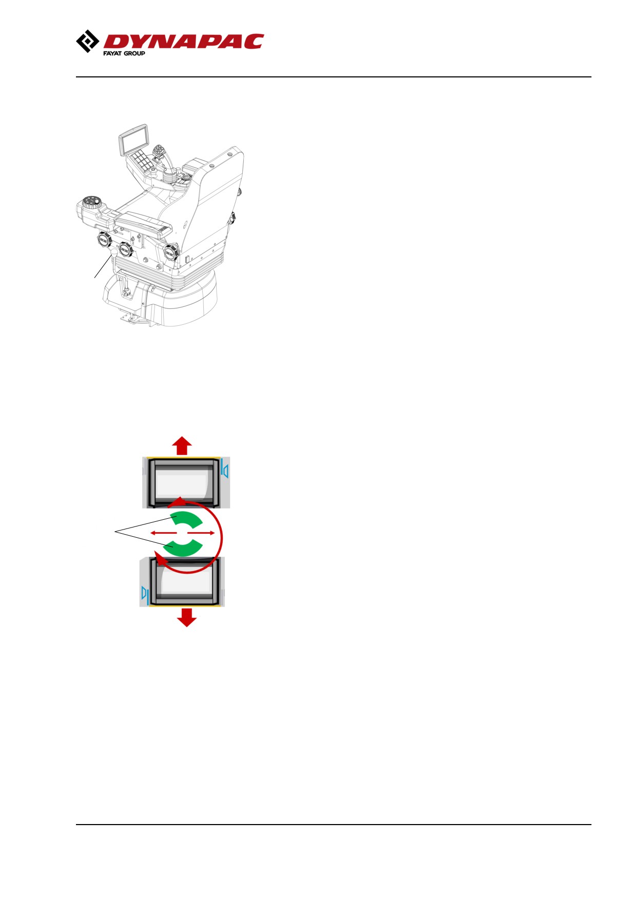
Positioning driver´s seat (reversible driver´s
seat) - Adjustments (Optional)
The driver´s seat unit has two adjustments, transverse
travel and rotation.
Pull the lever (1) forward (A) to release the transverse
travel catch for transverse travel.
Pull the lever (1) backwards to perform rotation. (B)
Find your ideal position. Ensure that the control unit
locks in position before operating the machine.
1
Fig. Driver´s seat (reversible driver´s
seat)
1. Lever - transverse travel/rotation
Forward
It's only possible to operate the machine when the
seat is locked within marked area (2) (illustrated in the
picture on the left).
If you change the rotation position of the driver´s seat
unit outside marked area or from one marked area to
the other, the forward/reverse lever must be moved to
neutral position before it is possible to operate the
machine again.
2
To adjust the operator's seat, see the section for
basic/comfort seat.
If the machine is not stopped/or the lever is set to
neutral before changing seat position:
• The machine slows down distinctly but gently.
• To make the machine move again, the forward/reverse
Backward
lever must be in neutral and wait for 3 seconds.
• The forward/backward direction of the lever has now been
2. Possible seat positions
changed so that the lever is pointing in the direction that
the machine moves when the lever is moved forwards or
backwards.
• The function of the electronic mini steering wheel has
been changed so that the machine turns logically when
the steering wheel is turned.
69
Operation
Adjust all settings when the machine is stationary.
Always ensure that the seat is in locked position
before operating the roller.
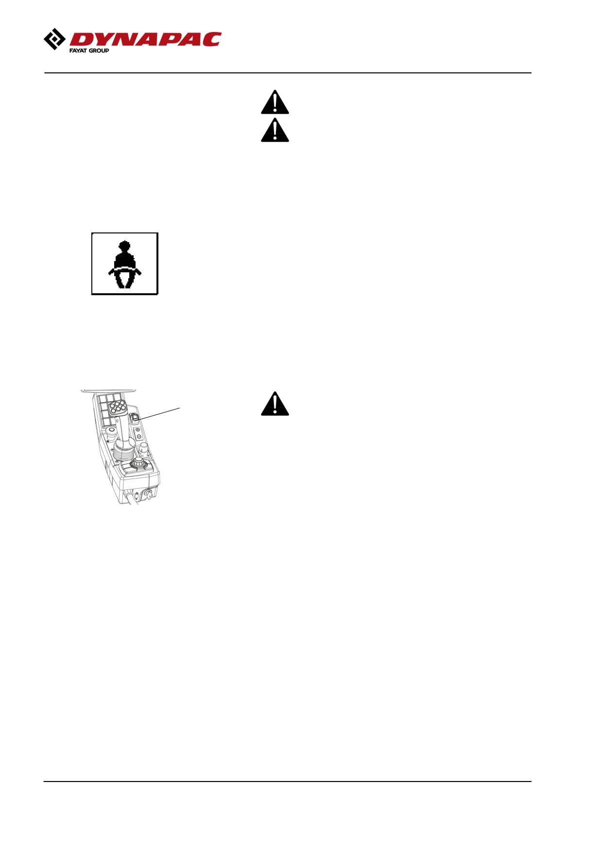
Belt reminder
The machine can be equipped with seat belt with belt
reminder.
Unless the seat belt is used, a warning image appear
in the display and a warning buzzer sounds to alert the
driver to use the seat belt.
Parking brake
Ensure that the parking brake (1) is definitely
1
switched on.
The brake is always applied in Neutral. (activated
automatically after 2 seconds)
Fig. Control panel
The parking brake must be activated to start the
1. Parking brake
machine!
70
Operation
Display - Control
2
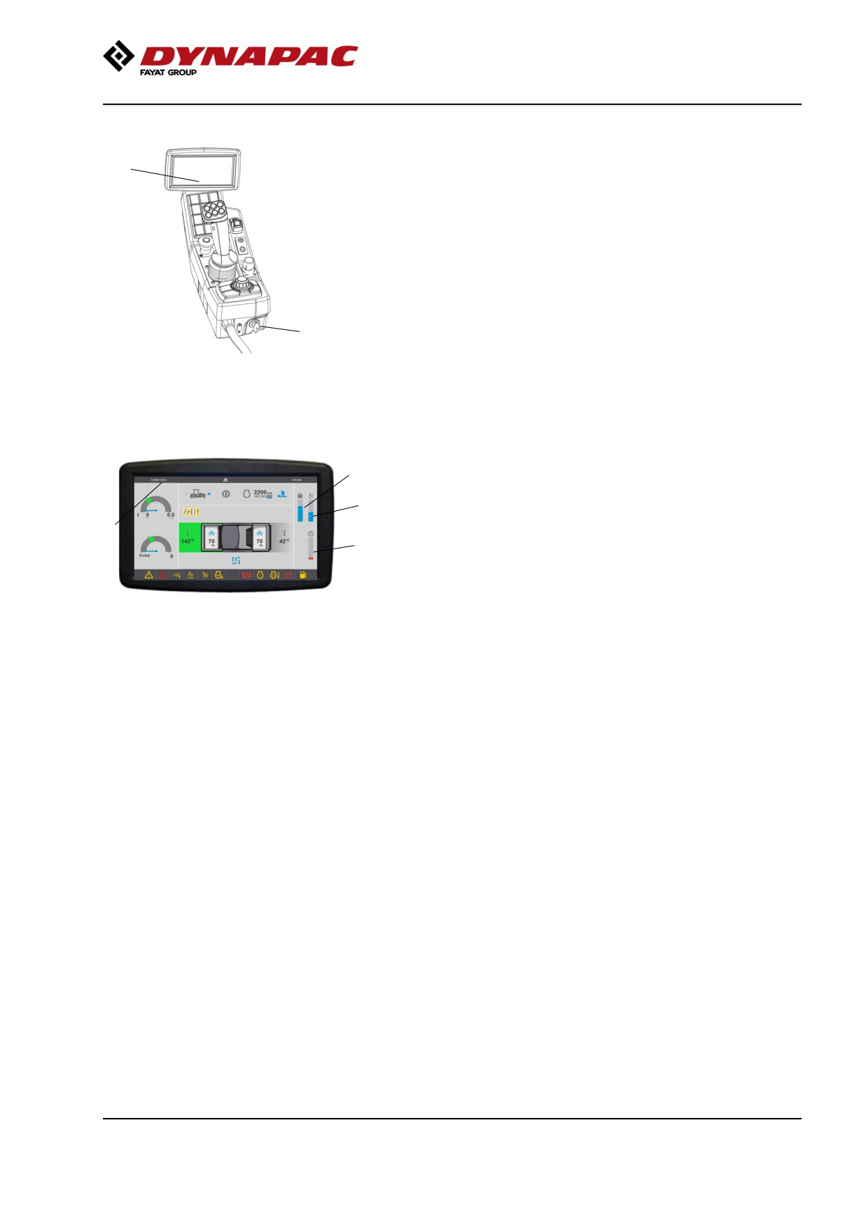
Sit down for all operations.
Turn the ignition key (1) to the right so that a start
image is shown on the display. Wait until the start
image (2) goes out and the status image is shown on
the display.
1
Fig. Instrument panel
1. Ignition key
2. Status image
3
Check that the urea level (6) is not too low, the other
level gauges (3, 4) show readings and that charging
6
shows at least 24V.
5
The hourmeter (5) registers and shows the total
4
number of hours the engine has run.
Fig. Status image
3. Fuel level
4. Water level
5. Hourmeter
6. Urea level
71
Operation
Interlock
The roller is equipped with Interlock.
The diesel engine with switch off after 7 seconds if the
operator gets off the seat when going
forwards/backwards.
If the control is in neutral when the operator stands up
a buzzer will go on until the parking brake is activated.
If the parking brake is activated, the diesel engine will
not stop if the forward/reverse lever is moved out of
neutral.
The diesel engine will switch off immediately if for any
reason the forward/reverse lever is moved out of
neutral when the operator is not sitting down and the
parking brake has not been activated.
Sit down for all operations!
72
Operation
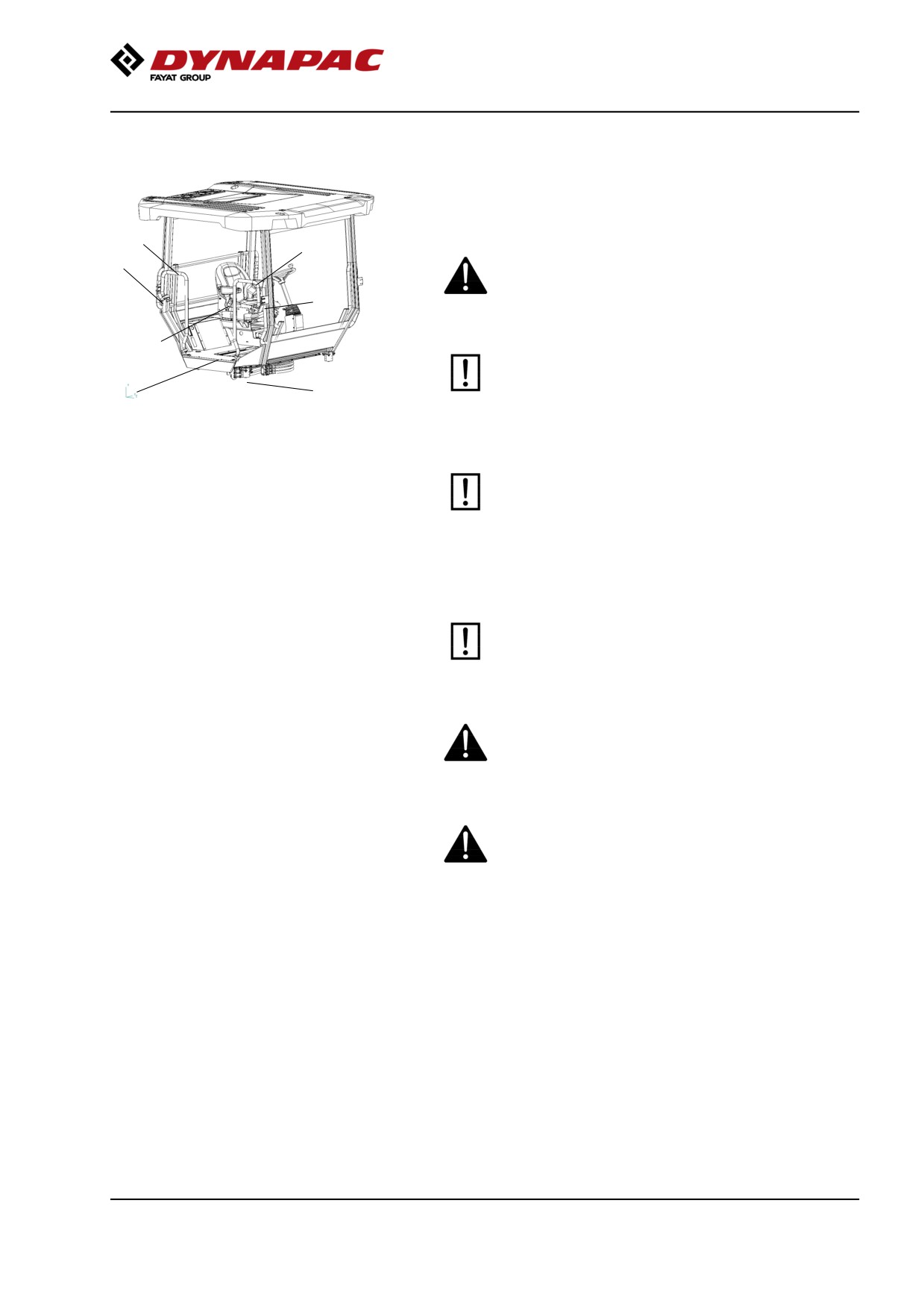
Operator position
If a ROPS (Roll Over Protective Structure) or a cab is
fitted to the roller, always wear the seat belt (1)
provided and wear a protective helmet.
2
2
3
Replace the seat belt (1) if it shows signs of
wear or has been subjected to high levels of
3
force.
1
The safety rails (2) around the cab are adjustable
in the inner and the outer positions. Pull in the
5
4
rails when driving close to walls or other
obstacles, and when transporting the machine.
Fig. Operator position
1. Seat belt
2. Safety railing
3. Locking knob
4. Rubber element
Inspect the ROPS/Cab for damages. Contact
5. Anti-slip
your supervisor for further actions if damages
are detected.
Release the locking knob (3), set the the railings in the
required position and relock in position.
Check that the rubber elements (4) on the
platform are intact. Worn elements will reduce
comfort.
Ensure that the anti-slip (5) on the platform is in
good condition. Replace where anti-slip friction is
poor.
If the machine is fitted with a cab, make sure that
the door is closed when in motion.
73
Operation
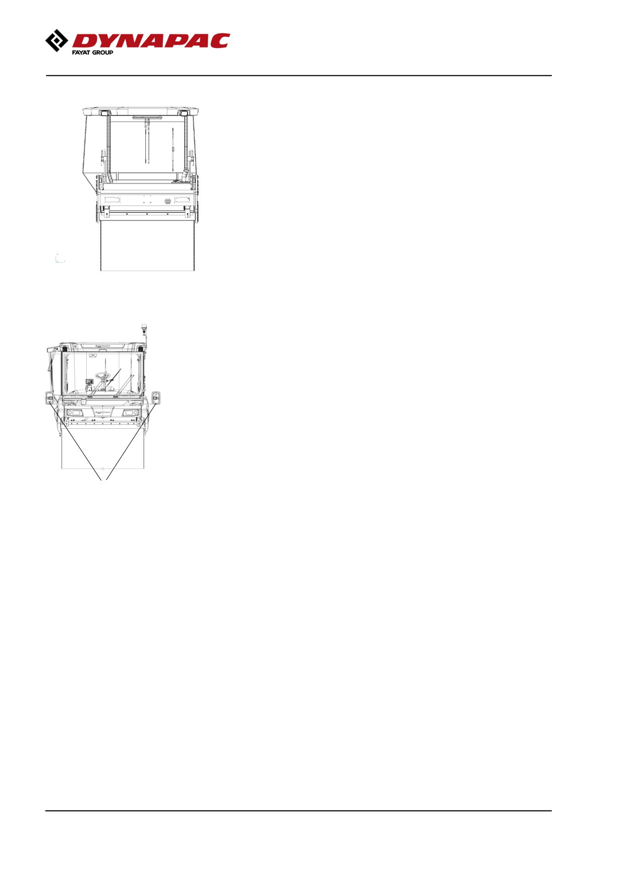
View
Before starting, make sure that the view forwards and
backwards is unobstructed.
All cab windows should be clean and the rear view
mirrors should be correctly adjusted.
Fig. View
Rear view mirrors - Adjustment
The rear view mirror adjustment is accessible from the
ground.
The arm of the rear-view mirror has a stop in the
maximum extended position. The mirror may then be
adjusted for a good rear view.
The visibility requirement is fulfilled as per standard
ISO 14401.
All rear view mirrors must be clean and adjusted for
good backward visibility.
1
Fig. Rear view mirrors
74
Operation
Foldable rotating beacon (Accessory)
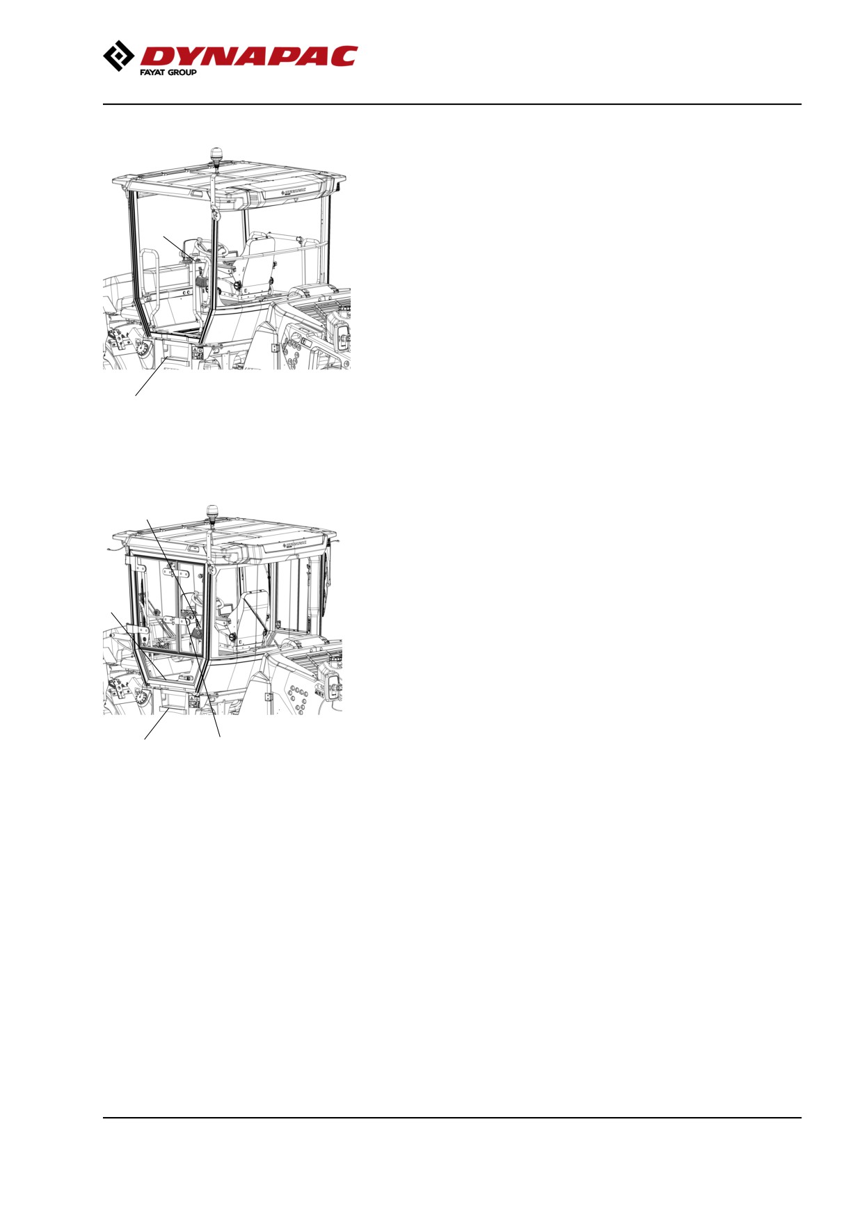
Stand firmly with both feet on the top step (1).
On a machine equipped with ROPS, hold a firm grip
with one hand, on the left rear side rail (2) on the
2
operator platform.
1
Fig. ROPS equipped roller
1. Step
2. Handrail
5
On a machine equipped with a cab, make sure that the
door (3) or the rear side window (4) on the door is
open. Take a firm grip with one hand, on the handle
(5) located on the left-hand rear cab pillar.
3
1
4
Fig. Cab equipped roller
1. Step
3. Cab door
4. Side window
5. Handle bar
75
Operation
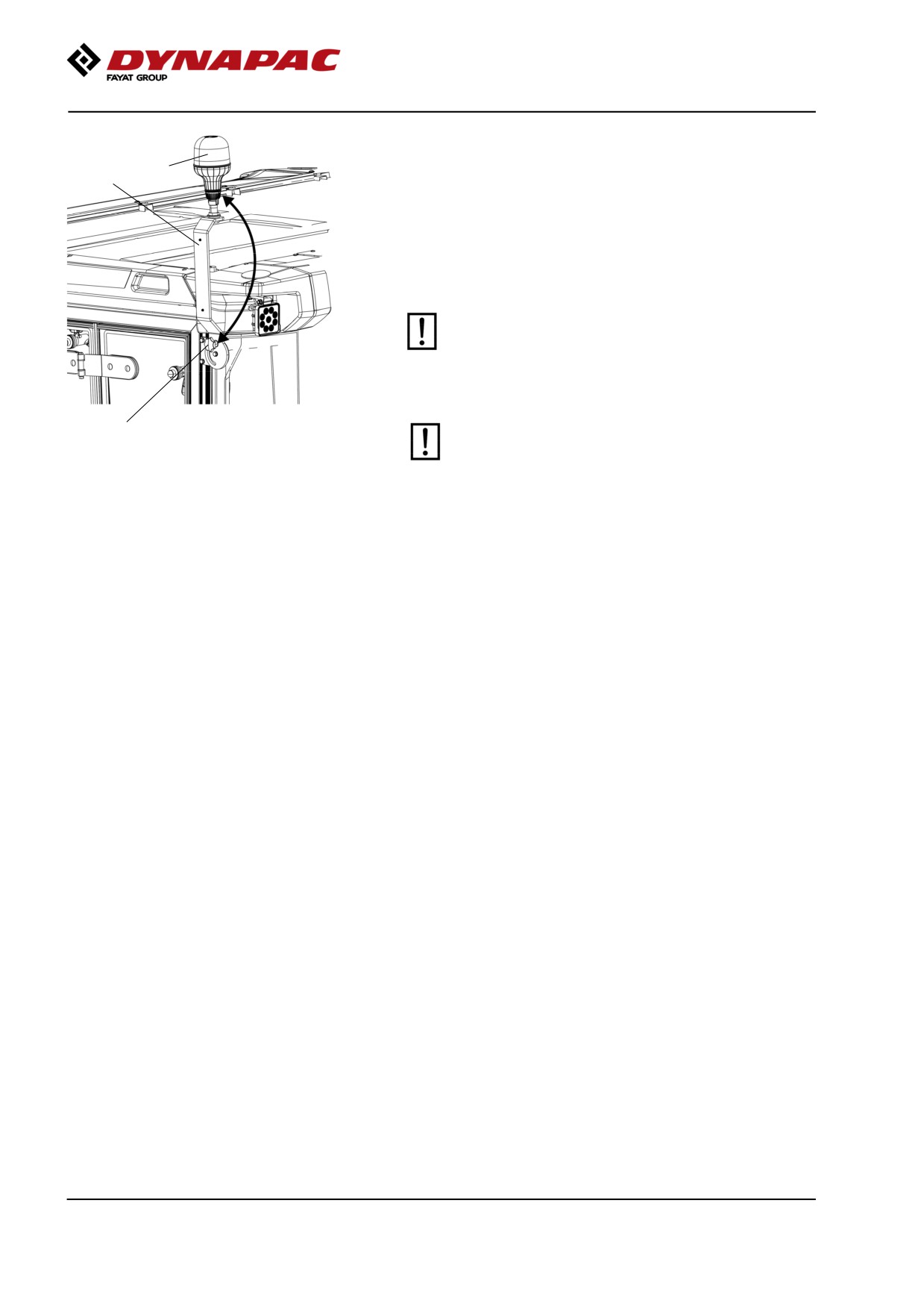
Now loosen the knob (6) with the other hand and fold
8
down the lamp holder (7).
7
Undo and remove any warning light (8) from the lamp
holder.
To raise the rotating beacon, perform the above
procedure in reverse.
The rotating beacon should always be folded down
before transport, where the total height of the
trailer is less than three meters.
6
Prior to starting work, make sure that the rotating
beacon is not damaged and in working order. If
not, replace immediately.
Fig. Rotating beacon
6. Knob
7. Lamp holder
8. Warning light
Working lights - Adjustment
Use a ladder for easier access to adjust the working
lights.
Cab windows - de-icing
To de-ice the cab windows, stand steadily on the cab
step, or the water tank filling step.
Use a telescopic ice scraper and de-ice the windows
as far as you can reach.
Adjust the seat to the left position for the best view
through the de-iced section of the window.
Turn on the defroster fully, and the remaining part of
the windows will be de-iced within a few minutes.
Wiper blade - Replacement
Ensure that the wiper blades are in good condition.
Replace the blades when they no longer wipe the cab
windows clean.
Use a ladder for easier access for wiper blade
replacement.
76
Operation
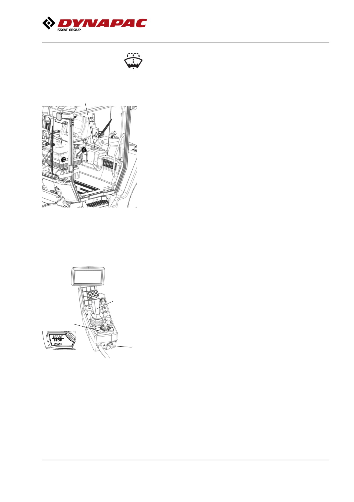
Washer fluid - Checking and filling
Place the roller on a level surface.
1
Top up the washer fluid when if necessary, in the
reservoir (1) located behind the operator’s seat.
The reservoir holds 2.1 liters (2.2 qts)
Fig. Operator’s platform
1. Washer fluid reservoir
Starting
Starting the engine
Make sure that the emergency stop is not activated,
but the parking brake is switched on.
Set the forward/reverse lever (1) in neutral position.
1
The diesel engine cannot be started in any other
position of the controls.
3
2
Fig. Control panel
1. F/R lever
2. Ignition key
3. Start-stop button
77
Operation
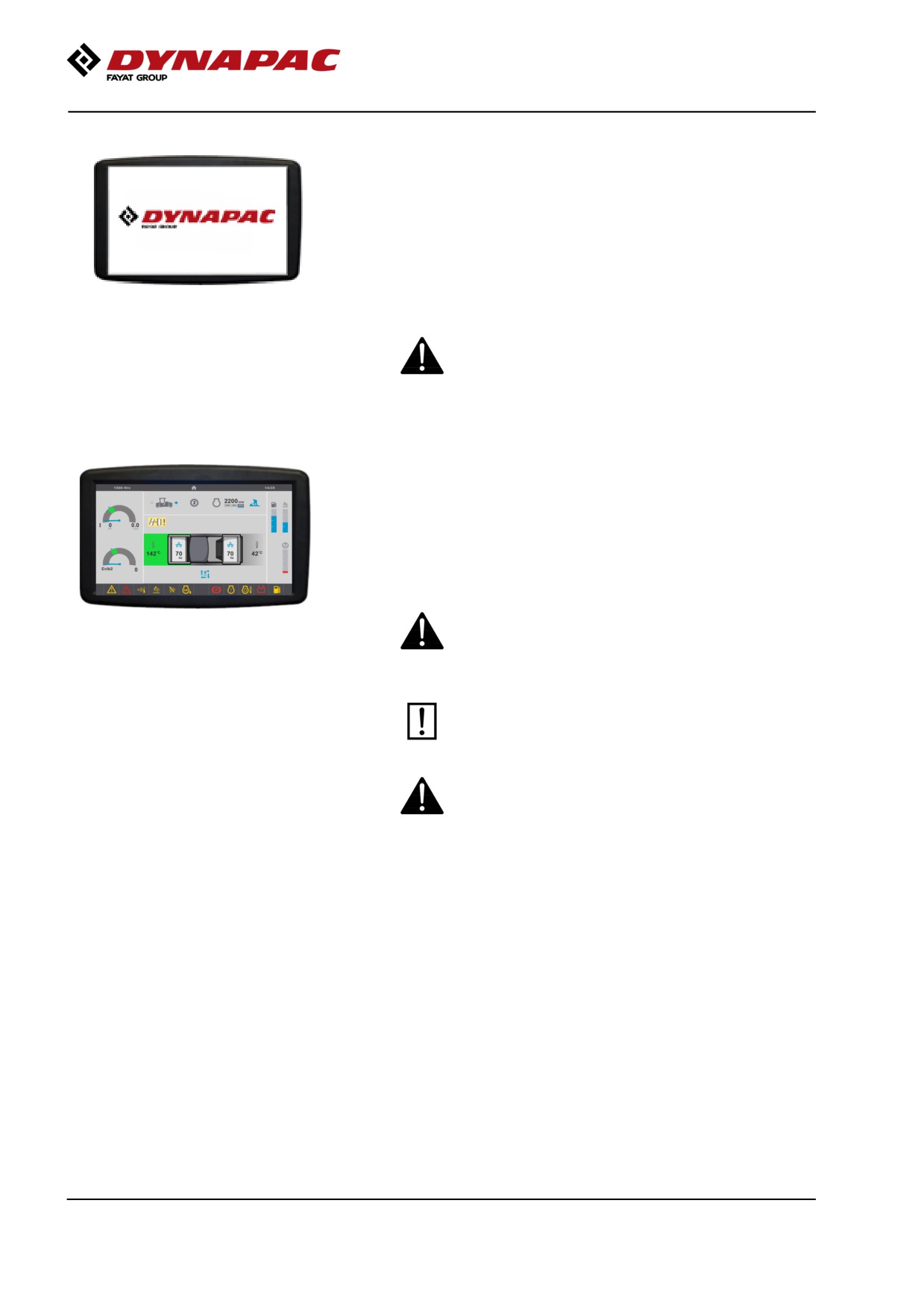
Turn the ignition key (2) to the right and a start screen
appears on the display. Wait until the start screen
turns off.
Activate start by pressing the start-stop button (3). The
status image appears on the display.
The system will automatically take care of essential
measures such as preheating and activation of the
Fig. Display - Start screen
starter motor.
Ensue that there is good ventilation (air extraction)
if the engine is run indoors. Risk of carbon
monoxide poisoning.
When starting the diesel engine when the ambient
temperature is lower than +10°C (50°F), the machine
should be warmed up at idle (low speed) until the
hydraulic oil temperature exceeds +10°C (50°F).
During warm up check that the fuel, urea and water
indicators shows the levels and the charge shows at
least 24V.
When starting and driving a machine that is cold,
remember that the hydraulic fluid is also cold and
Figure. Display - Status image
that braking distances can be longer than normal
until the machine reaches the working temperature.
The machine always starts in the Transport
position, without it being possible to use off-set,
vibration or sprinkling.
If the machine and drums are in off-set mode,
switch to work mode and reset before loading the
machine on a truck. This is indicated by a warning
in the display.
78
Operation
Parking brake test
To be sure that the parking brake works and is in good
condition, perform following procedure daily.
Put the machine on flat ground.
2
1
Make sure that there are no obstacles in the
direction of travel, on the ground, in front of or
behind the roller, or overhead.
3
4
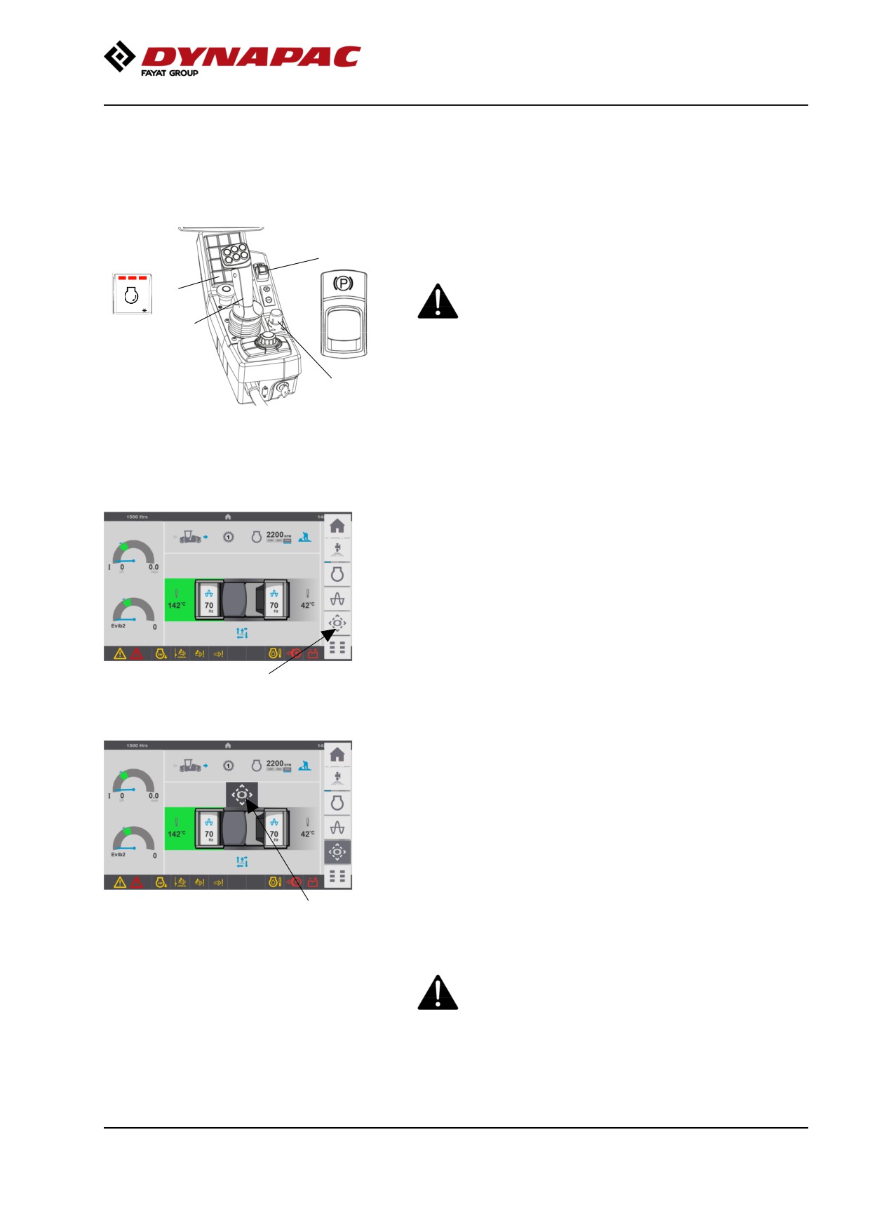
Activate the parking brake with the parking brake
Fig. Control panel
button (2). Turn on the quick selection menu on the
1. Rpm switch
display, the brake test button (5) is now visible in the
2. Parking brake
menu bar on the touch screen.
3. Forward/Reverse lever
4. Speed limiter
Set the engine speed (1) to medium or high speed and
set the propulsion speed limiter (4) to max., i.e. no
limitation.
Push the brake test button (5) in the touch screen on
the display and keep it pushed, a pop-up symbol (6)
shows on the screen when the button is activated.
NOTE! This activation is not possible to do from the
display controller knob.
5
Fig. Display view
By pressing the brake test button, it is possible for
5. Brake test button
the machine to run against the brakes and thus
test the brakes under load.
Wait 2-3 seconds and move the forward/reverse lever
(3) slowly forward and slowly back to neutral again
and then release the brake test button (5).Be
prepared for the machine to move during this
operation.
Then stop the machine by immediately pulling the
lever to neutral
If the machine does not move the parking brake effect
is approved.
6
Fig. Display view
If the machine moves the parking brake is not
6. Pop-up symbol (parking brake test)
approved and brake discs are considered as worn
out and need to be replaced.
The machine must be immediately taken out of
operation and must not be used until the brakes
are repaired and approved.
79
Operation
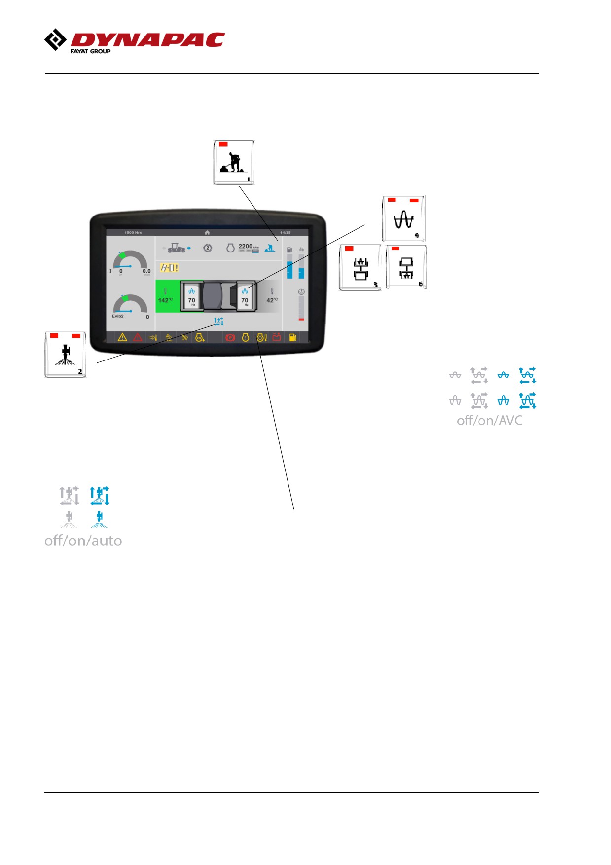
Display when activating choice via the button
set.
Working mode, offset and vibration possible.
Low amplitude/High
amplitude
Vibration on front
and rear drums.
Automatic vibration control (AVC
active), is selected in
"settings-compaction", vibration is
activated when the Forward/Reverse
lever is outside of neutral.
Watering, manual/automatic
Automatic water control (auto active),
watering is activated when the
Forward/Reverse lever is outside of
neutral.
Warning alarm display, see the table for
details.
80
Operation
Driving
Operating the roller
Under no circumstances is the machine to be
operated from the ground. The operator must be
2
seated inside the machine during all operation.
1
3
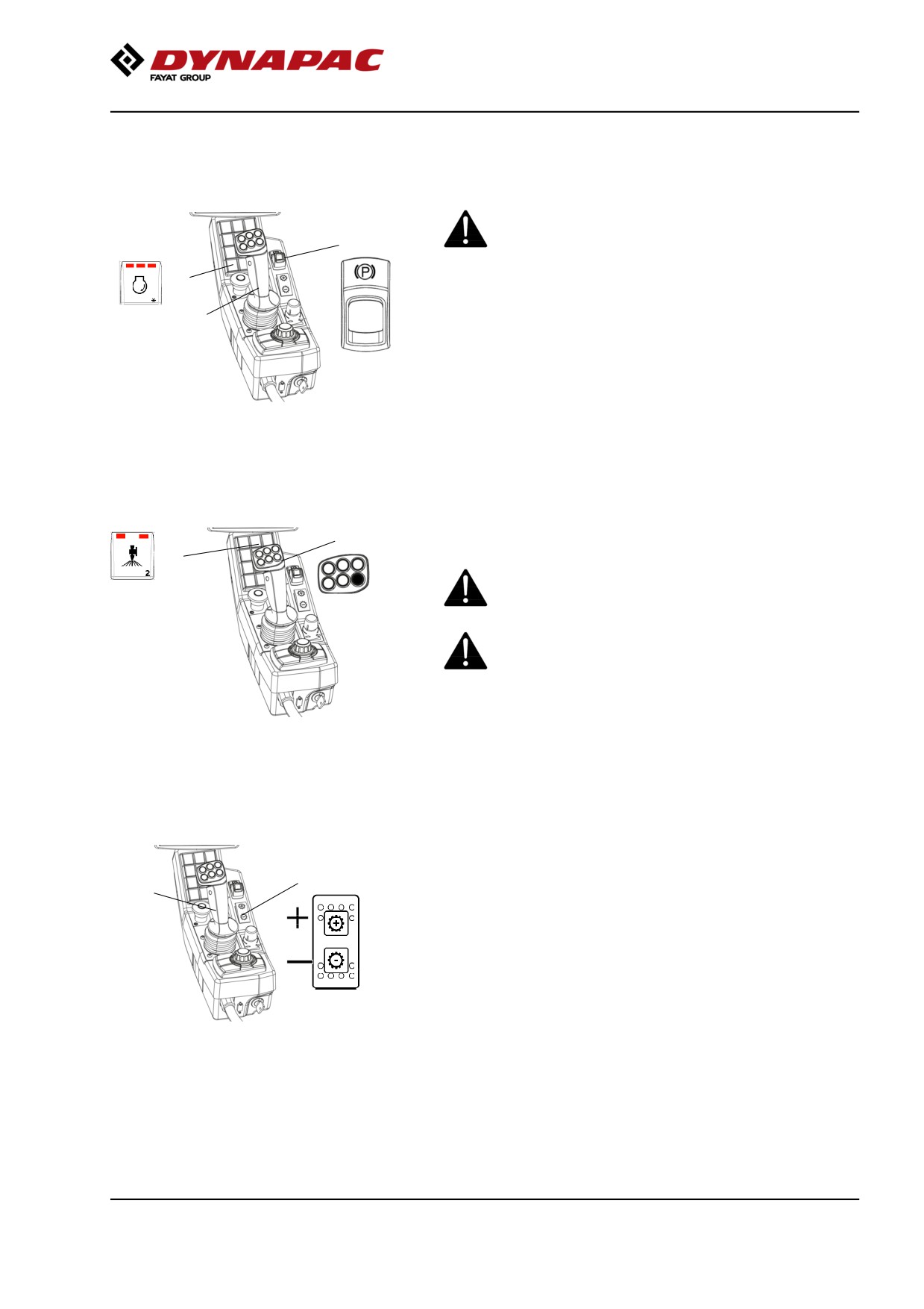
Activate working speed (1) = HI or ECO if available.
In ECO, the machine automatically regulates the
engine speed according to requirements.
Fig. Control panel
1. Rpm switch
If the machine is only to be transported, MID or ECO
2. Parking brake
should be selected instead.
3. Forward/Reverse lever
Check that the steering is working correctly by turning
the steering wheel once to the right and once to the
left while the roller is stationary.
5
When compacting asphalt, remember to turn on the
4
sprinkler system (4) or (5).
Make sure that the area in front of and behind the
roller is clear.
Release the parking brake (2).
4. Manual/automatic watering
5. Panic watering
Gear position switch
Switch (1) is a spring-return gear position switch,
where gear changing take place by stepping through
1
2
the two different gear positions: Position 1 and
Position 2.
• Position 1: Used for maximum hill-climbing capacity
during vibratory compaction
• Position 2: Used for maximum transport speed or
eventually for high speed doing static compaction passes
without vibration.
The forward/reverse lever must be in neutral in order
Fig. Control panel
1. Gear position switch
to change gear.
2. Forward/Reverse lever
81
Operation
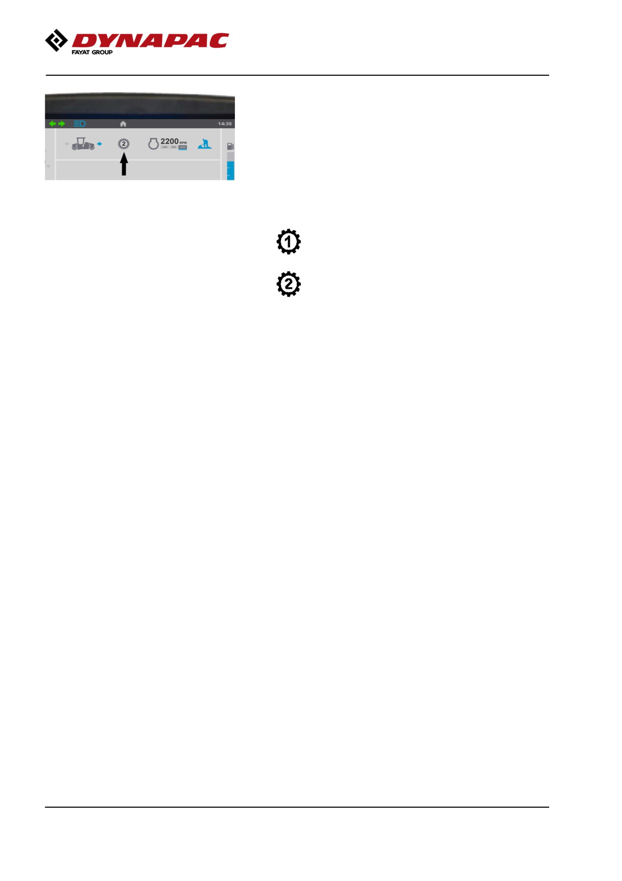
The machine's gear position is shown in the center of
the speedometer; select the gear/speed for the task.
Fig. The display shows the selection
(position 1 or 2)
Max. speed
= Position 1
6 km/h
3.8 mph
= Position 2
12 km/h
7.5 mph
Carefully move the forward/reverse lever (2) forwards
or backwards, depending on which direction of travel
is required.
The speed increases as the lever is moved away from
the neutral position.
82
Operation
Interlock/Emergency stop/Parking brake -
Check
The interlock, emergency stop and parking brake must
be checked daily before operating. A function check of
the interlock and emergency stop requires a restart.
The interlock function is checked by the operator
standing up from the seat when the roller is moving
very slowly forwards/backwards. (Check in both
directions). Hold the steering wheel firmly and brace
yourself for a sudden stop. A buzzer goes on and after
7 seconds the engine switches off and the brakes are
activated.
Check the function of the emergency stop by pressing
the emergency stop button when the roller is moving
slowly forwards/backwards. (Check in both
directions). Hold the steering wheel firmly and brace
yourself for a sudden stop. The engine switches off
and the brakes are activated.
If a function error is detected when testing the
emergency stop, this should be replaced immediately.
Check the function of the parking brake by activating
the parking brake when the roller is moving very
slowly forwards/backwards. (Check in both
directions). Hold the steering wheel and brace yourself
for a sudden stop when the brakes are activated. The
engine does not switch off.
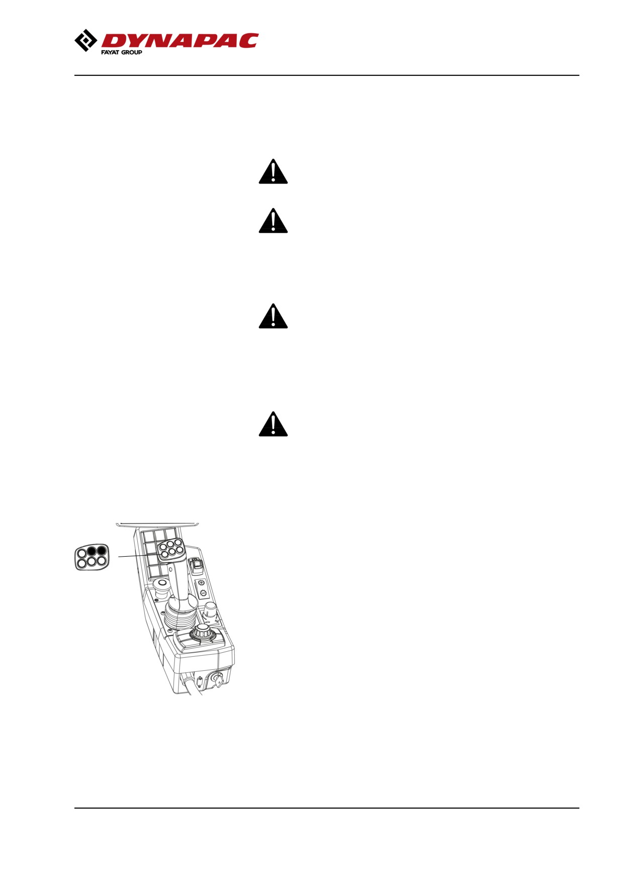
Pivotal steering (Optional)
The machine must be in the Working mode to activate
the pivotal steering. Use the two front buttons (1) on
the forward/reverse lever to operate the pivotal
steering.
1
To reset the front drum to neutral, adjust the buttons
(1) until the machine has aligned the drums.
When steering from the outer positions towards
neutral, the pivotal steering will always stop in neutral.
This is in order to end up in neutral. If you wish to pass
through the neutral position, you may release the
button and press it again.
On machines with electronic steering (reversible
drivers seat) automatically centering of the front drum
Fig. Forward/reverse lever
could be achieved by pressing both offset buttons at
1. Pivotal steering
the same time.
83
Operation
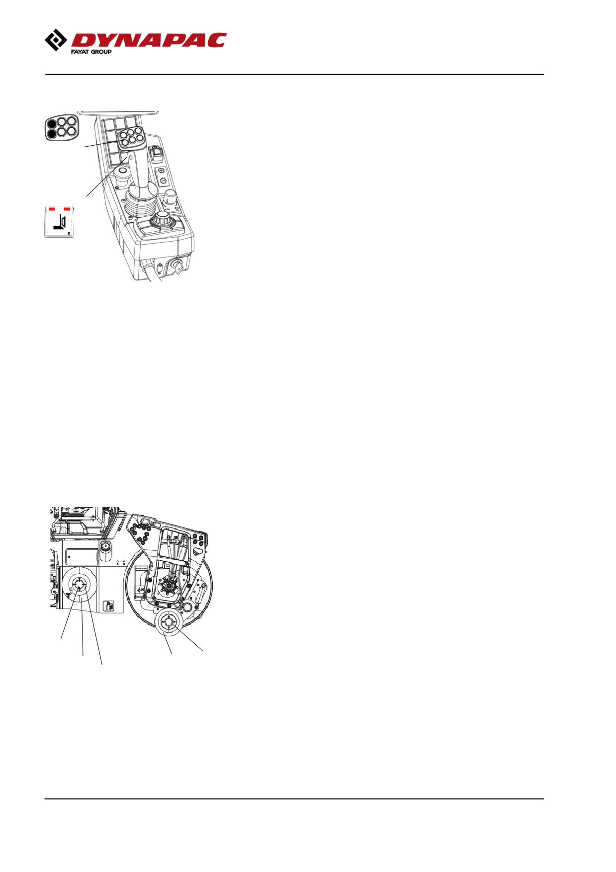
Edge cutting (Optional)
The machine must be running to activate the edge
cutter/compactor.
2
Selection with button (1) for use of the left or right
edge cutter and the sprinkler valve for the selected
edge cutter.
Water sprinkling of the joint cutter is carried by
activating the drums’ regular sprinkler system and then
1
running in auto mode at the set interval.
Sprinkling of the joint cutter can also be carried out by
pressing and holding the blue button on the control
lever.
When the machine is in Working mode and if the lower
left button on the lever (2) is pressed, the edge
Fig. Switch
cutter/compactor is lowered to the asphalt surface by
1. Edge cutter, left/right
means of a hydraulic cylinder. To return the edge
2. Edge cutter/compactor, Up/Down
cutter/compactor to its original position, press on the
upper left button on the lever to lift the edge
cutter/compactor.
Note that the joint cutter/edge press can also be lifted
if the machine is in Transport mode.
A bypass valve prevents the hydraulic system being
overloaded.
The standard sprinkler system should be activated first
to avoid asphalt sticking to the joint cutter/edge press.
Now press and hold blue button on the front/reverse
lever in order to spray water on the joint cutter/edge
press.
There are two tools to choose between: a cutter wheel
for joint cutting and a conical compaction wheel for
edge pressing. In the figure the joint cutter (1) is
mounted for work. The edge cutter (2) can easily be
replaced with the edge press by loosening the bolted
joint (3).
4
3
2
1
3
Fig. Replacing the tool
1. Edge press
2. Joint cutter
3. Bolted joints
4. Holder for cutter/press wheel
84
Operation
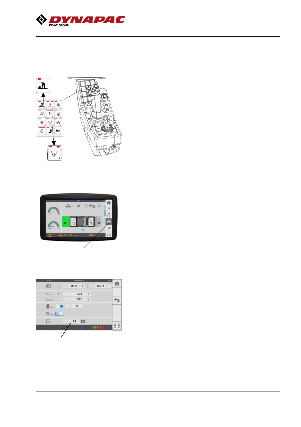
Chip spreader (accessory)
Activate the button for Working mode (1).
Chip spreading is started with the button (2) on the
control panel keypad.
1
The button can activate the chip spreader in two ways,
Manual or Automatic spreading
Left LED, manual spreading, gives continuous
spreading.
Activation of the right LED gives automatic spreading
(auto active), spreading is activated when the
Forward/Reverse lever is outside of neutral.
Press until the LEDs go out to shut down the chip
spreader completely.
2
Adjusting the feed volume
Fig. Control panel
1. Working mode
The quantity of chips spread per square metre is
2. Chip spreader
adusted by changing the speed of the feed roller.
This setting/adjustment is made via the display in the
Compacting menu. This can be reached directly from
the start screen by selecting Compacting on the
quick-choice menu.
Compacting
Fig. Home page with quick-choice
menu
Adjust spreading volume with minus for lower volume
and plus for higher volume of chips.
Spreader volume
%
Fig. Compacting
85
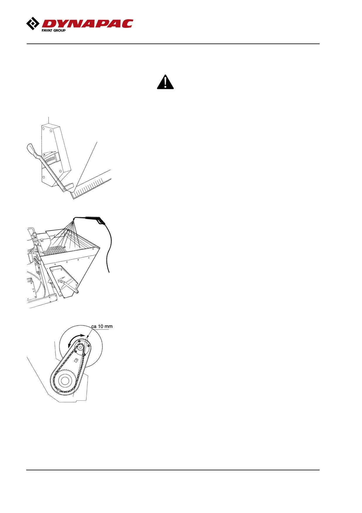
Operation
Preparations before adjustment / emptying.
The machine should be placed on a level surface
with the engine switched off and brake applied.
Emptying
Empty the spreader by setting it in transport mode
over the required area and by fully opening the lever
on the left-hand side.
Washing the spreader
When corrosive material has been used the spreader
must be flushed clean with water.
This should also be done when the spreader is not to
be used for a long period.
Adjusting the chain 1
Loosen the four bolts for the bearing housing and turn
it to the correct position, where the chain has a
clearance of approx. 10 mm. Tighten the bolts.
86
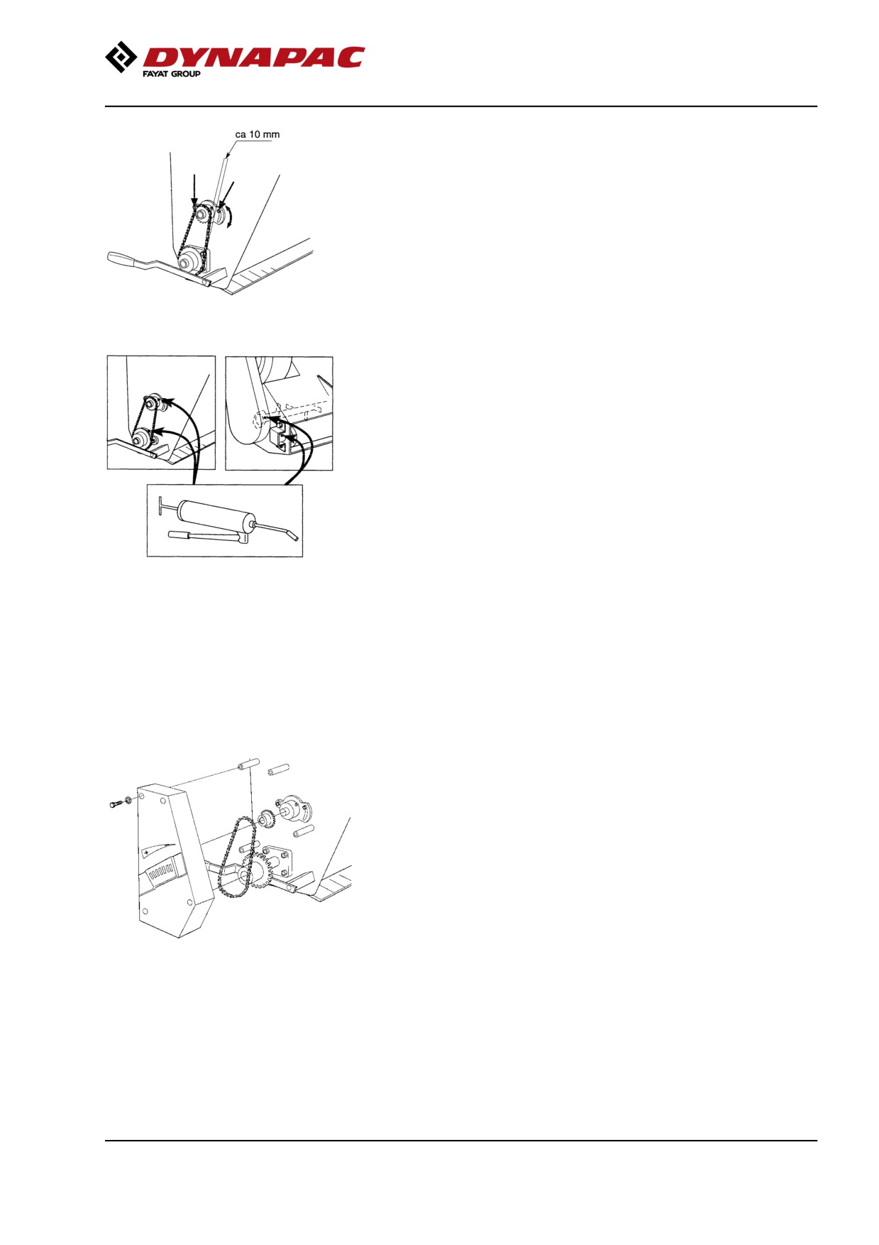
Operation
Adjusting the chain 2
Loosen the two nuts, see arrows, for the bearing
housing and turn it to the correct position, where the
chain has a clearance of approx. 10 mm. Tighten the
nuts.
Lubrication
At the start of every season and after every 40 hours
of operation. Once per season is sufficient during
infrequent use.
Lubricate after every season before putting into
storage.
Changing the brush drum.
Release the protective cover.
Remove the chain.
Remove the chain wheel on the outfeed drum and
mixer shaft.
Release the screws and pull off the chain wheel.
87
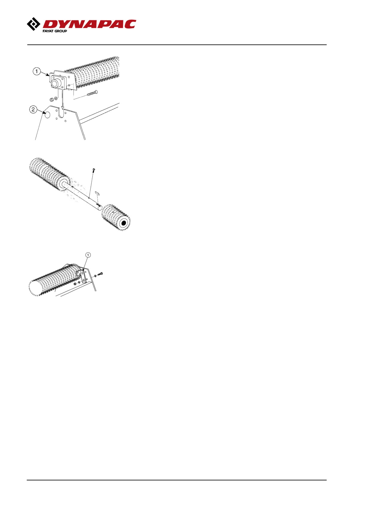
Operation
Release the eight screws holding the outfeed drum.
Lift off the drum and bearing.
Unscrew the outfeed rubber.
Changing the brushes.
Remove the bearings and seals.
Remove the old brushes and fit the new brushes.
Refit the assembled brush drum in the spreader.
Fit the scraper iron and rubber mat.
Fit the scraper iron attachments (No.1) left and right.
Adjust the scraper iron so that it goes 1-3 mm into the
brush.
Adjust the rubber mat so that it is flush with brush,
approx. 5 mm.
88
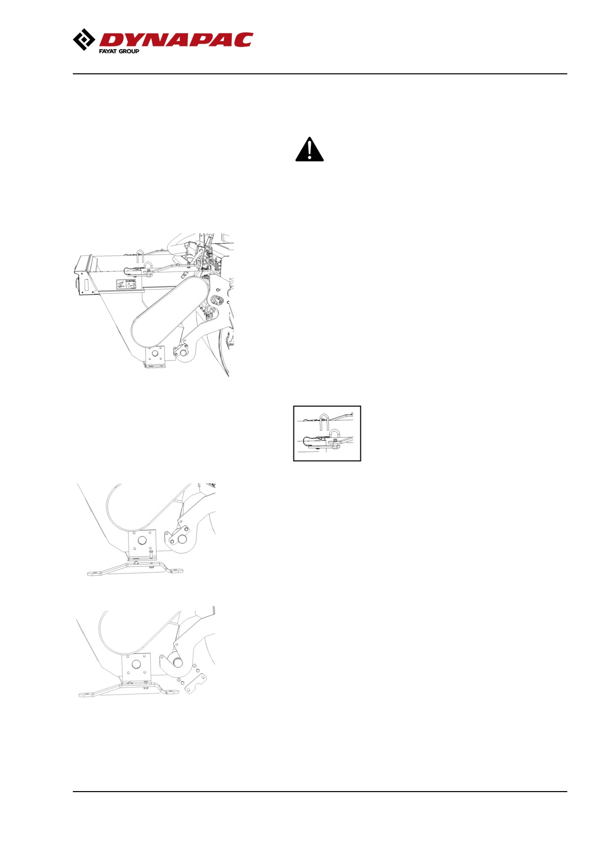
Operation
Preparations before dismantling/assembly.
The machine should be standing on a level surface
with the engine switched off and the brakes on.
Use safe handling equipment to lift the chip
spreader off/on. Make sure no-one is in the lifting
area, risk of bodily and crushing injuries.
Make sure that the container is empty and does not
contain any extra material before dismantling.
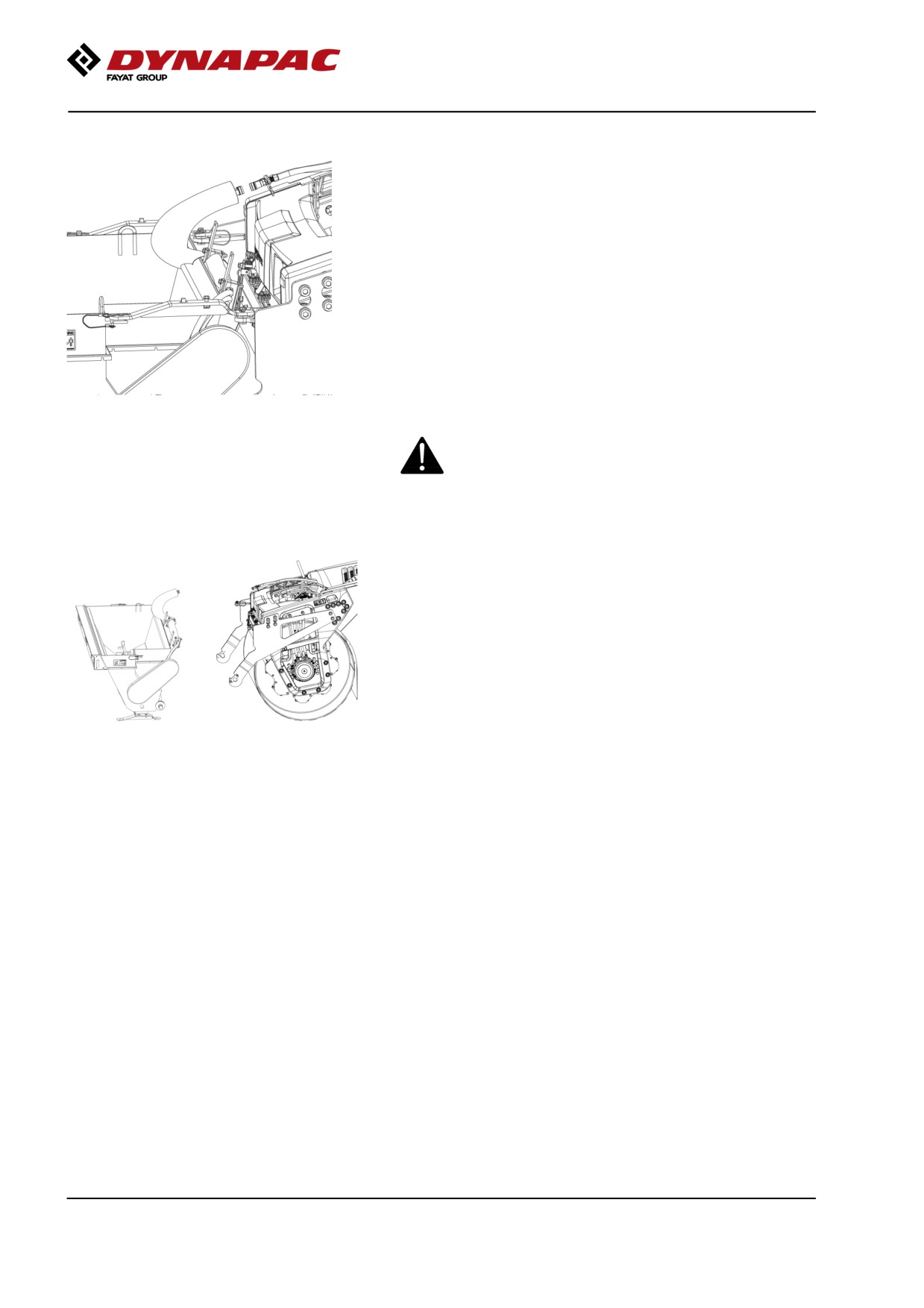
Attach the lifting devices in the eyes on both sides of
the container.
1- Release the pin in the clamp and remove the clamp
from the machine.
1
2- The clamp is now fitted at the base of the container
as a foot.
3- Release the lock on the lower shaft.
2
3
89
Operation
4- Release the hydraulic hoses and cabling.
Plug the hoses (dust seals) with the enclosed plugs.
5- Now lift off the container with the requisite lifting
device and place on a level surface.
4
Always place a parked container in a safe place
away from traffic and marked with reflectors so
that it can also be seen at night.
6- Refit the protective beam on the suspension arms.
To fit the container, follow the instructions in the
reverse order.
5, 6
90
Operation
Vibration
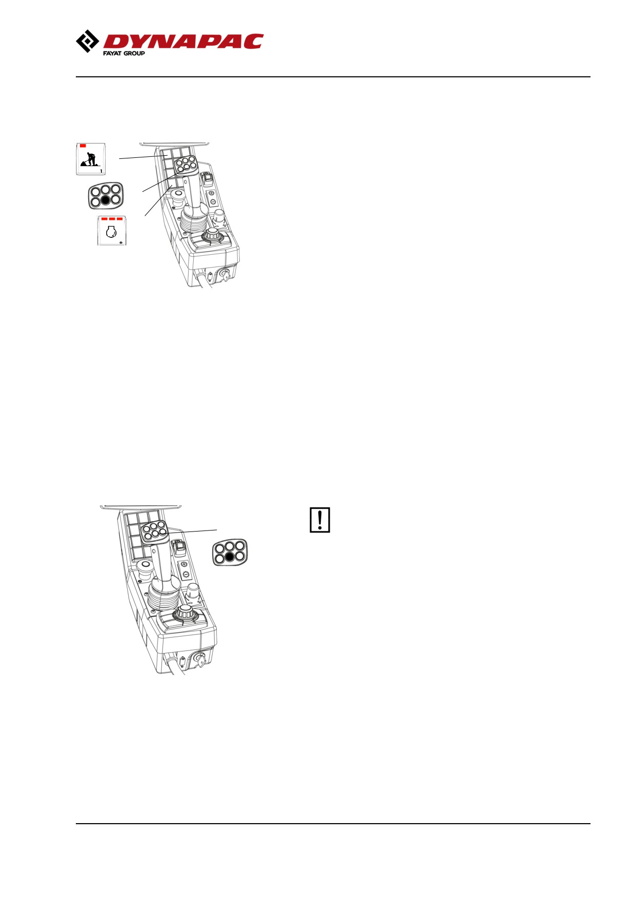
Manual/Automatic vibration
4
Activate the button for the Working mode (4).
In the manual position the operator has to activate the
vibration via the bottom left switch on the
2
forward/reverse lever (2).
Automatic vibration control (AVC active), is selected
3
via the display in "settings-compaction", vibration is
activated when the Forward/Reverse lever is outside
of neutral.
In automatic mode (AVC), vibration is activated when
the speed is ≥ x km/h (... mph) and turns off at a speed
Fig. Control panel
of x km/h (...mph)
2. Switch, vibration ON/OFF
3. Speed selector
Activation of vibration for the first time, as well as
4. Working mode
disconnection of automatic vibration, are performed
with the switch (2) on the forward/reverse lever.
Note that vibration can only be activated when the
working mode (4) is activated, and when the Rpm
switch (3) for the engine is in high (HI) or Eco
mode (ECO). After 10 seconds in neutral, the
vibration is switched off and the machine drops to
low speed.
Manual vibration - Switching on
Never activate vibration when the roller is
1
stationary. This can damage both the surface and
the machine.
Engage and disengage vibration using the switch (1)
on the front of the forward/reverse lever.
Always switch off vibration before the roller comes to a
standstill.
When compacting thin layers of asphalt up to approx.
50 mm (2 inches) thick, the best results are achived
with low amplitude/high frequency.
Fig. Forward/reverse lever
1. Switch, vibration ON/OFF
91
Operation
Amplitude/frequency - Changeover
The amplitude setting must not be change when
2
vibration is in operation
Switch the vibration off and wait until vibration
stops before changing amplitude.
3
1
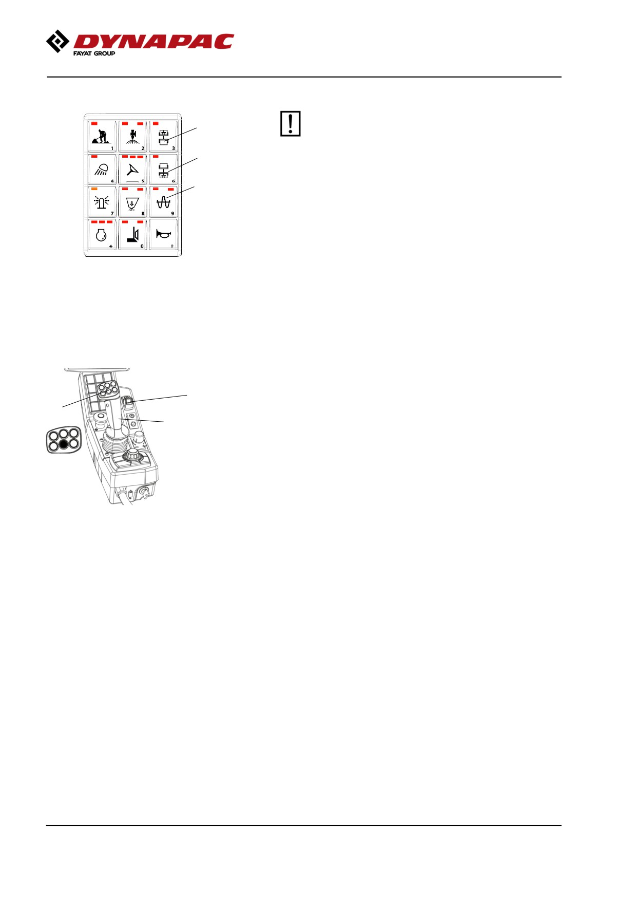
By pressing button (1) high amplitude is achieved.
The buttons (2) and (3) are used to get vibrations
either on front or rear drum or on both.
- (2) vibration on front drum.
Fig. Control panel
1. High amplitude
- (3) vibration on rear drum.
2. Vibration fron drum
3. Vibration rear drum
Braking
Service brake
3
1
Press the switch (1) to switch off the vibration.
2
Move the forward/reverse lever (2) to the neutral
position to stop the roller.
Always activate the parking brake (3), before leaving
the operator platform.
Fig. Control panel
1. Vibration On/Off switch
2. Forward/Reverse lever
3. Parking brake
If the forward/reverse lever is moved quickly (forwards
or backwards) toward/past neutral, the system
switches to a rapid braking Mode and the machine
stops.
Activate normal driving Mode again by moving the
forward/reverse lever back to neutral.
92
Operation
Reserve brake
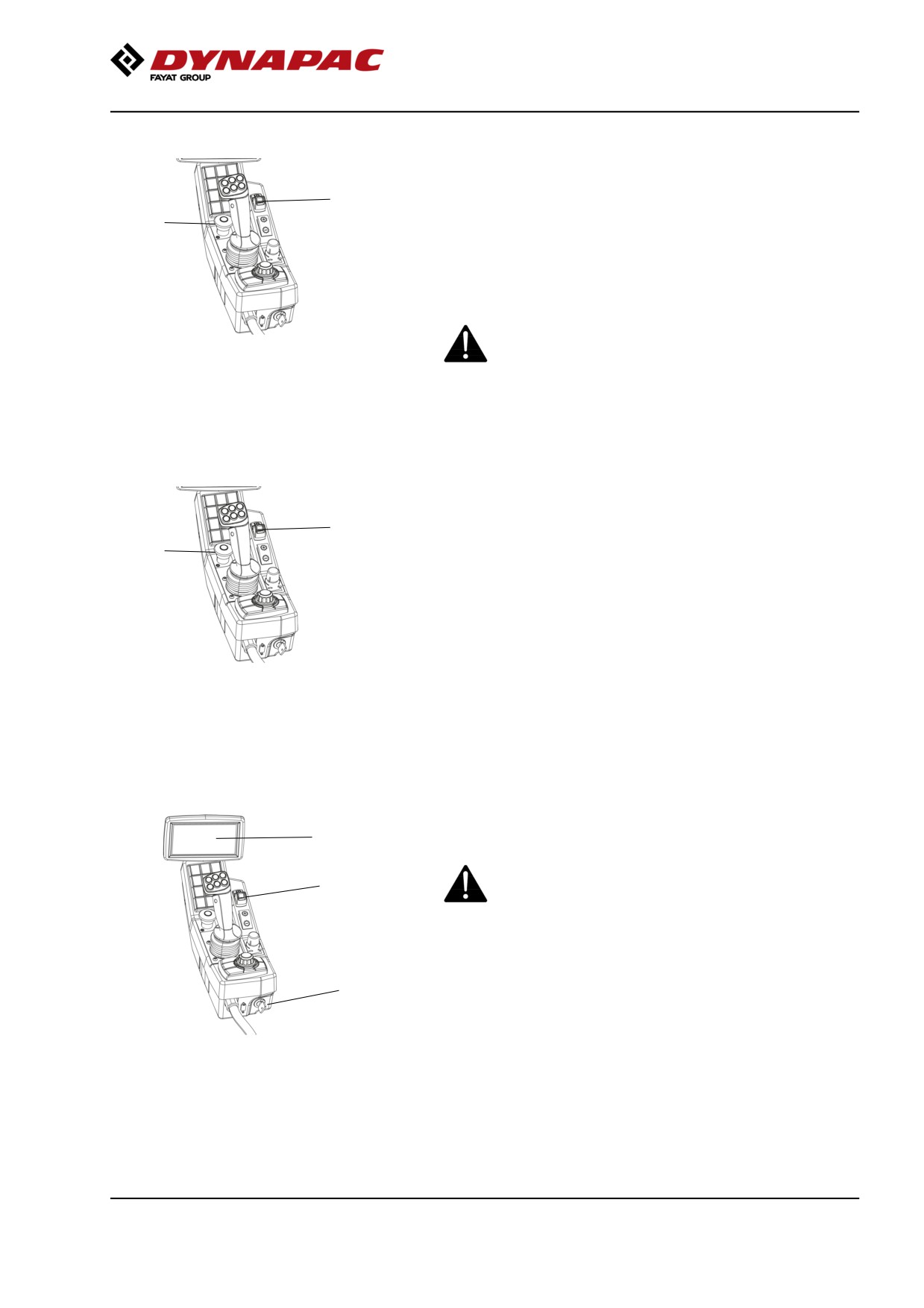
Braking is normally activated using the
forward/reverse lever. The hydrostatic transmission
2
retards and slows the roller when the lever is moved
1
towards the neutral position.
In addition, there is a disc brake in the drive motors
that acts as a reserve brake when operating, and as a
parking brake when stationary (then activated with the
parking brake button (2)).
For reserve braking, press the parking brake
Fig. Control panel
button (2), hold the steering wheel firmly and be
1. Emergency stop
prepared for a sudden stop.
2. Parking brake
Emergency stop
The emergency stop is activated by pressing the
button (1).
2
1
Hold the steering wheel firmly and brace yourself for a
sudden stop.
The brake is applied and the engine stops.
After an emergency stop, return the forward/reverse
lever to neutral and deactivate the emergency stop by
pulling up the button (1).
Fig. Control panel
1. Emergency stop
Activate the parking brake (2) and the engine can be
2. Parking brake
restarted.
Switching off
1
Set the speed control in idling position and allow the
engine to idle for a few minutes to cool down.
Do not leave the engine idling for too long periods.
3
Long periods of idling, more than 10 minutes, can
cause poor engine performance and, if there is a
particulate filter, the service life is reduced
significantly.
2
Check the display to see if any faults are indicated.
Switch off all lights and other electrical functions.
Activate the parking brake (3) and then turn the
Fig. Control panel
ignition lock (2) to the left to the off position.
1. Display
2. Ignition lock
3. Parking brake
Fit the instrument cover on the display and top of the
control box (on rollers without cab), and lock it.
93
Operation
Parking
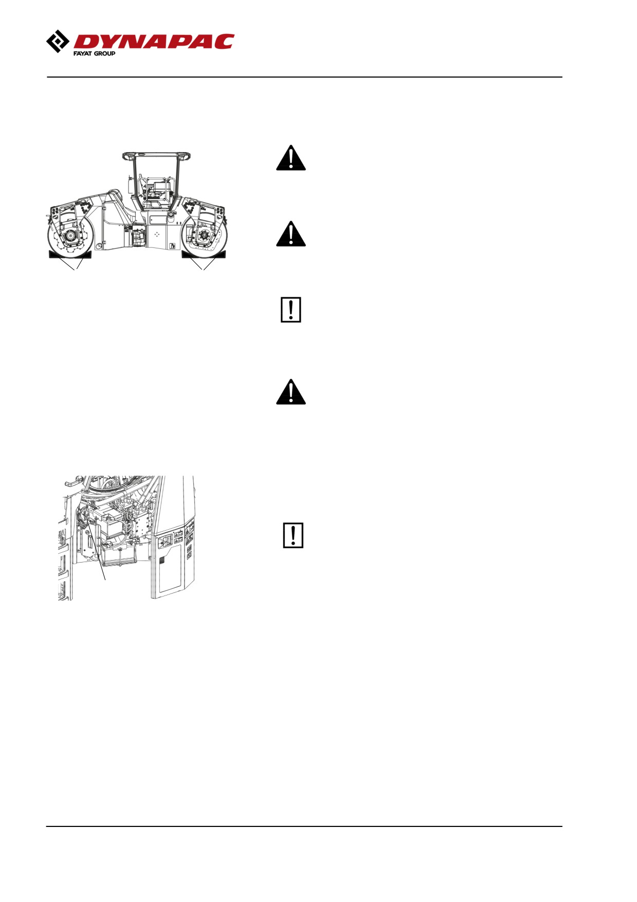
Chocking the drums
Never get off the roller when the diesel engine is
running, without first activating the parking brake.
Make sure that the roller is parked in a safe place
with respect to other road users. Chock the drums
if the roller is parked on sloping ground.
1
1
Fig. Arrangement
Keep in mind that there is a risk of freezing during
1. Chock
the winter. Drain the water tanks, pumps and
water lines.
Fill antifreeze in the engine cooling system and
the washer fluid reservoir in the cab. Also see
maintenance instructions.
Before using the roller again, make sure that
the engine is switched off and the parking
brake is activated. The brake chocks can then
be removed
Master switch
Before leaving the roller for the day, switch the master
switch (1) to the disconnected position and remove the
handle.
Before switching off the master switch, wait for at
least 30 seconds after the ignition lock has been
switched off, in order to avoid the engine's
electronic control unit (ECU) sustaining damage.
1
Figure. Engine door, left
1. Master switch
This will prevent battery discharging and will also
make it difficult for unauthorized persons to start and
operate the machine. Lock the service doors/covers.
94
Long-term parking
Long-term parking
The following instructions should be followed
when long term parking (more than one month).
These measures apply when parking for a period of up
to 6 months.
Before re-commissioning the roller, the points marked
with an asterisk * must be returned to the pre-storage
state.
Wash the machine and touch up the paint finish to
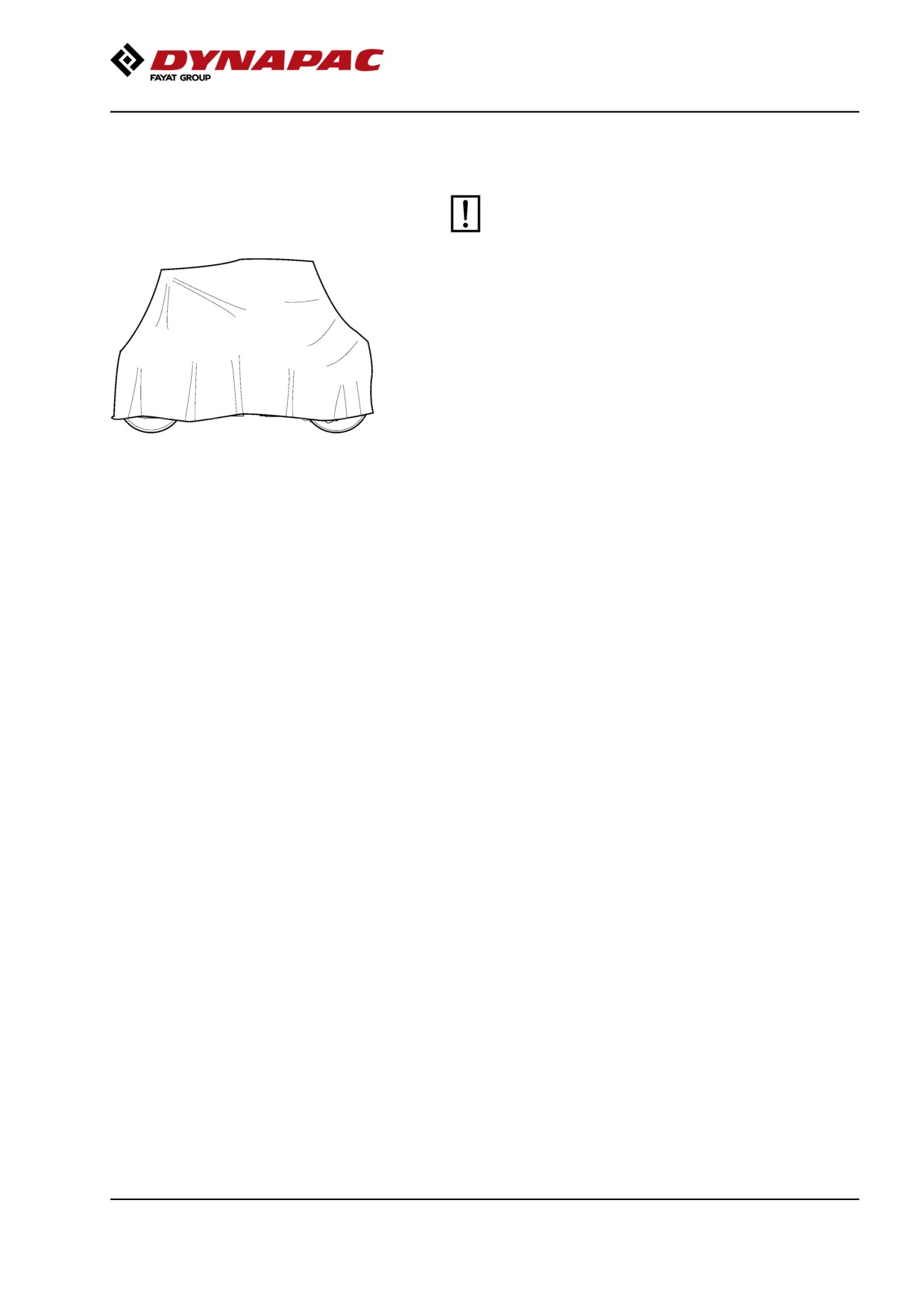
Fig. Roller weather protection
avoid rusting.
Treat exposed parts with anti-rust agent, lubricate the
machine thoroughly and apply grease to unpainted
surfaces.
Engine
* Refer to the manufacturer’s instructions in the engine
manual that is supplied with the roller.
Battery
* Dismantle the battery/batteries from the machine,
clean the outside and maintenance charge.
Air cleaner, exhaust pipe
* Cover the air cleaner or its opening with plastic or
tape. Also cover the exhaust pipe opening. This is to
avoid moisture entering the engine.
Watering system
* Empty the water tank and all hoses of water. Empty
the filter housing and the water pump. Undo all
sprinkler nozzles.
Fuel tank
Fill the fuel tank completely full to prevent
condensation.
Hydraulic reservoir
Fill the hydraulic reservoir to the uppermost level mark
(see under the heading ‘Every 10 hours of operation.’)
95
Long-term parking
Steering cylinders, hinges, etc.
Grease the steering cylinder pistons with conservation
grease.
Grease the hinges on the doors to the engine
compartment and the cab.
Engine coolant
Check that the coolant mix are within recommended
levels and have a freezing temperature lower than
expected lowest temperature during the storage period.
Urea tank (DEF tank)
Draining of the urea tank (DEF tank) is recommended
if left unused for more than 6 months.
Deliver the drained liquid to an
environmentally-friendly waste disposal station.
Hoods, tarpaulin
* Lower the instrument cover over the instrument
panel.
* Cover the entire roller with a tarpaulin. A gap must
be left between the tarpaulin and the ground.
* If possible, store the roller indoors and ideally in a
building where the temperature is constant.
96
Miscellaneous
Miscellaneous
Lifting
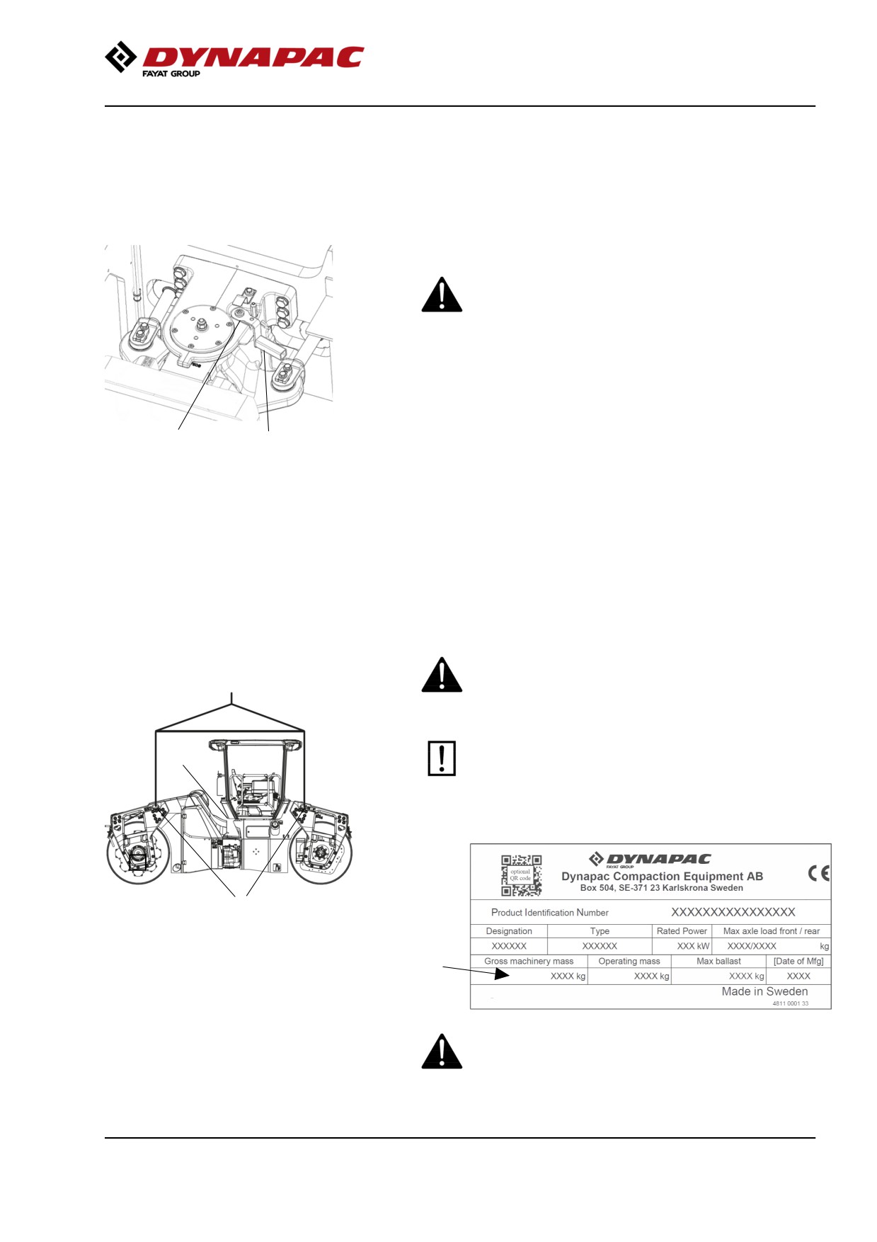
Locking the articulation
Articulation must be locked to prevent inadvertent
turning before lifting the roller.
Turn the steering wheel to the straight ahead position.
Activate the parking brake.
Front frame shall be in line with the rear frame.
2
1
Fig. Steering joint lock, locked
Lift lock in the handle (1) while it is turned clockwise.
1. Lock handle
2. Locking dowel
Make sure dowel (2) gets in position as illustrated.
Arm must be in contact with the surface of the molded
holder.
If this is not done, it's likely that the machine halves
are out of line, steer then the machine so this is
happening.
Lifting the roller
Weight: refer to the machine plate on the
The machine’s gross weight (3) is specified on the
roller
machine plate (2).
Lifting equipment such as chains, steel wires,
2
straps and lifting hooks must be dimensioned in
accordance with the relevant safety regulations
for the lifting equipment.
1
Fig. Roller prepared for lifting
1. Lifting point
2. Machine plate
3
Stand well clear of the hoisted machine! Make sure
that the lifting hooks are properly secured.
97
Miscellaneous
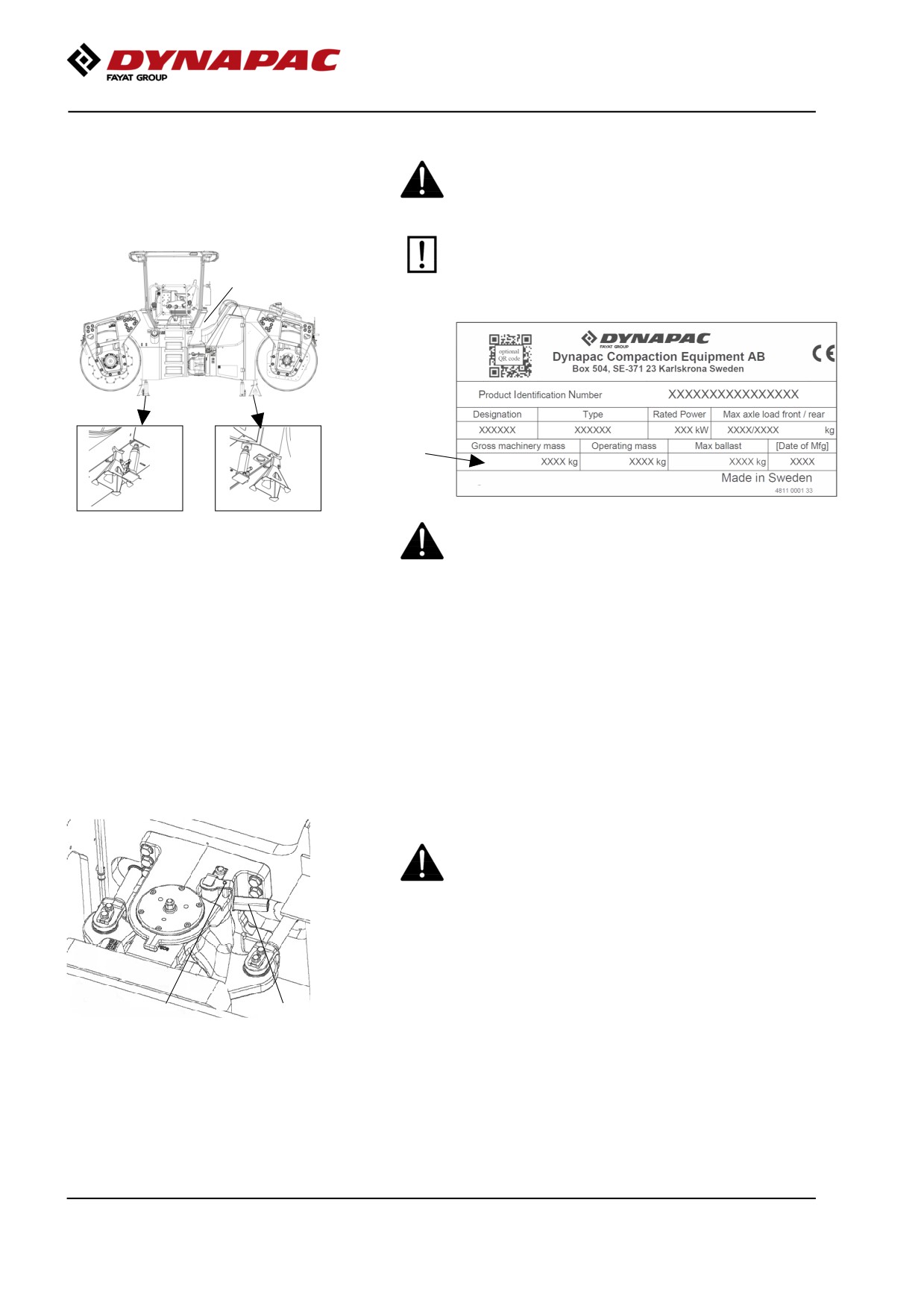
Lifting the roller with jack:
The machine’s gross weight (4) is specified on the
machine plate (1).
Weight: refer to the machine plate on the
The lifting device such as a jack (2), or
roller
equivalent, must be dimensioned according to the
safety regulations for lifting devices.
1
4
Figure. Roller lifted with jack
Do not go under a lifted load! Make sure that the
1. Machine plate
lifting device is secure in its position, and on a
2. Jack
level and stable suface.
3. Marking
The machine must only be lifted with a jack, or the
like, positioned as per the markings (3). The frame is
reinforced at these points to withstand the tension.
Lifting at any other place can result in damage to the
machine or personal injury.
Unlocking the articulation
Remember to restore the steering joint lock on the
steering joint to open before operating.
Lift lock in the handle while turning it counterclockwise.
Make sure lock gets in position on the dowel by trying
2
1
to turn the handle clockwise or counterclockwise
Fig. Steering joint lock, open
without lifting the lock.
1. Lock handle
2. Locking dowel
98
Miscellaneous
Towing/Recovering
The roller can be moved up to 300 meters (330 yards)
using the instructions below.
Short distance towing with the engine running
Activate the parking brake, and temporarily stop
the diesel engine. Chock the drums to prevent the
roller from moving
Open the left door to the engine compartment to
access the propulsion pump.
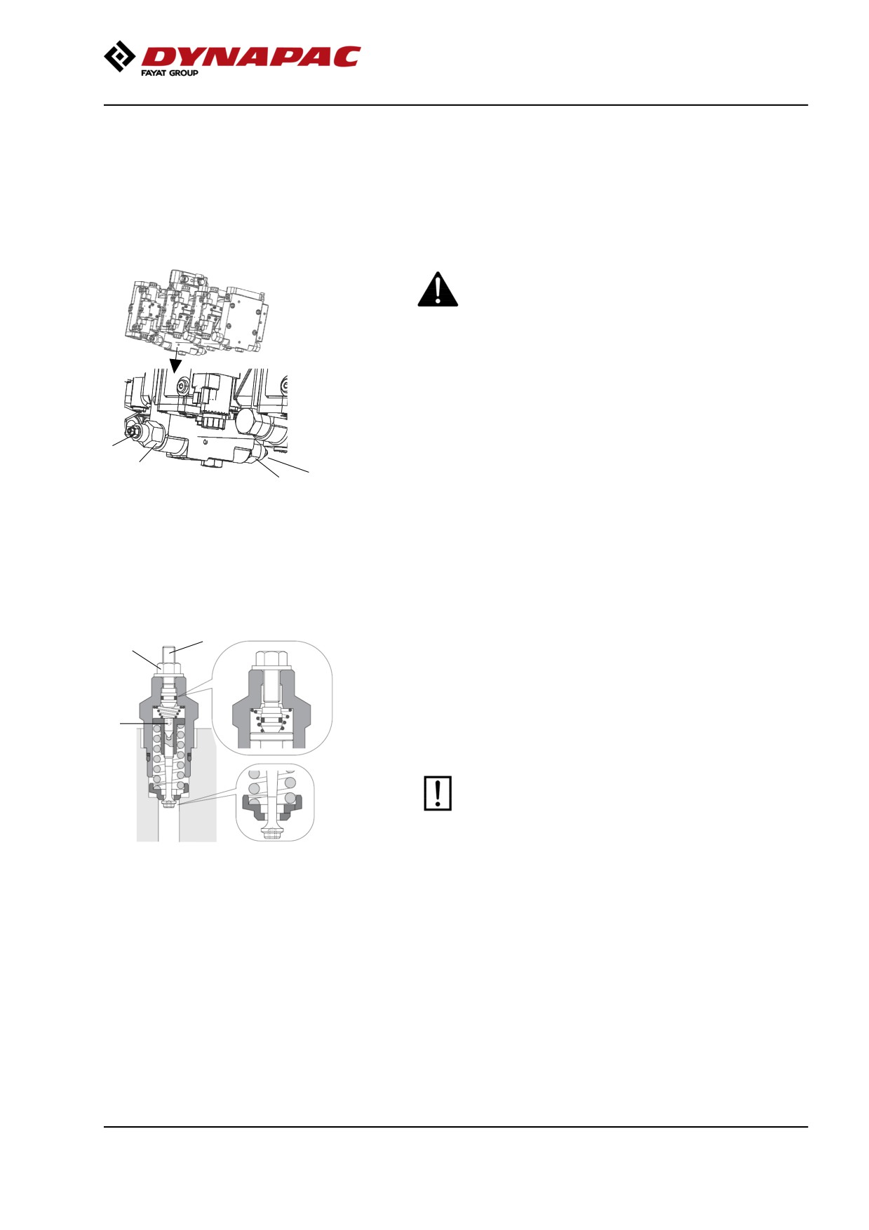
At the bottom on the forward drive pump are two
towing valves (1) which need to be set in bypass mode.
1
1
Loosen the towing valve (1) with the hexagonal nut (A)
2
2
by turning it a number of turns to the left, counter-hold
Fig. Propulsion pump
on the overflow valve (2).
1. Towing valve
2. Bypass valve
After releasing the hexagonal nut (A), screw in the
adjusting screw (B) with a hex key until it touches the
pin (C) and then turn an additional ½ turn. The valve is
now open.
B
Start the engine and allow it to idle.
A
Deactivate the parking brake and place the
forward/reverse lever in the forward or reverse
position. If the lever is in neutral, the brakes in the
hydraulic motors are activated.
C
The roller can now be towed and can also be steered
if the steering system is otherwise functioning.
Do not forget to reset the towing valves after
performing towing.
Figure. Towing valve
To leave the by-pass position, unscrew the adjusting
screw (B) until it stops and then lock the valve again
with the hex nut (A).
99
Miscellaneous
Short distance towing with the diesel engine
switched off/not running
Chock the drums to prevent the roller from moving
when the brakes are hydraulically disengaged.
Open the left door to the engine compartment to
access the propulsion pump.
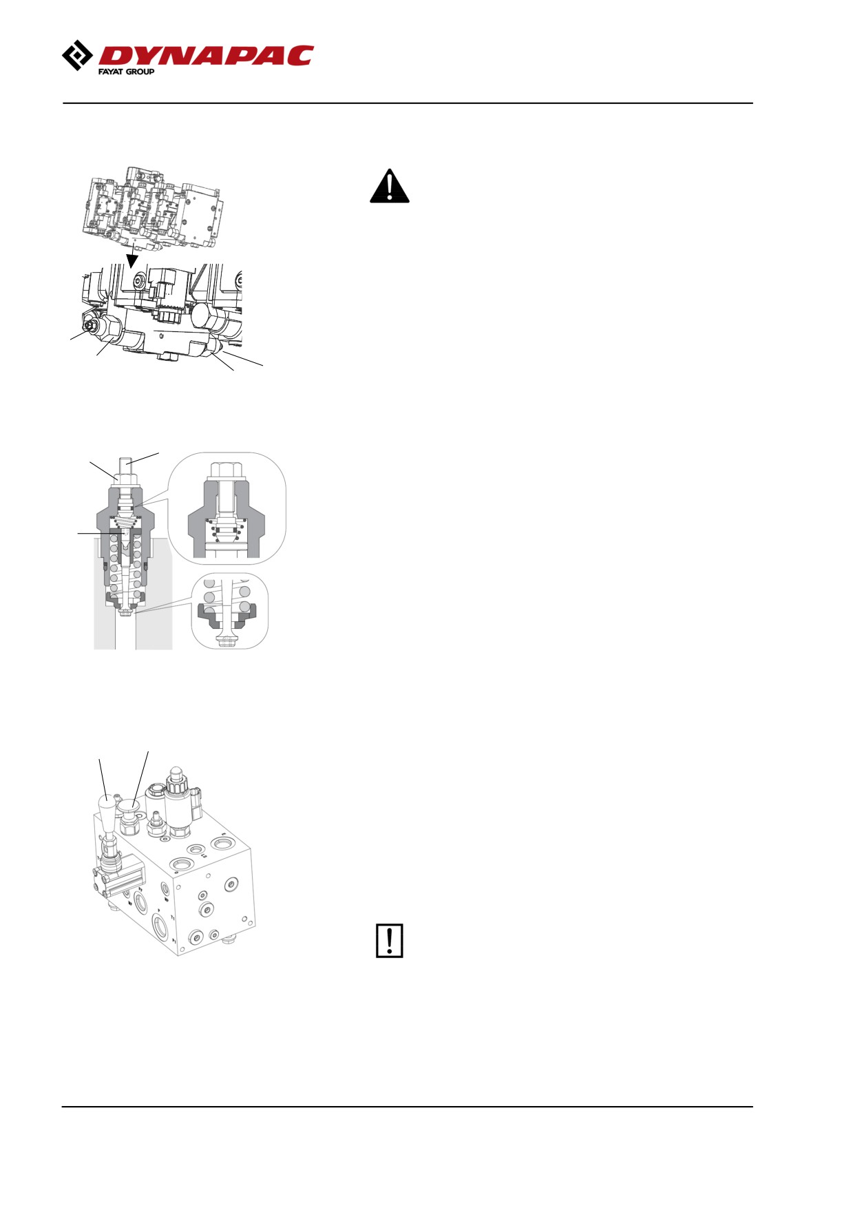
At the bottom on the forward drive pump are two
towing valves (1) which need to be set in bypass mode.
1
2
1
2
Fig. Propulsion pump
1. Towing valve
2. Bypass valve
B
Loosen the towing valve (1) with the hexagonal nut (A)
A
by turning it a number of turns to the left, counter-hold
on the overflow valve (2).
After releasing the hexagonal nut (A), screw in the
adjusting screw (B) with a hex key until it touches the
C
pin (C) and then turn an additional ½ turn. The valve is
now open.
Figure. Towing valve
3
The release pump for the brakes is located on the
4
valve block, which is positioned in the rear of the
engine compartment.
Press the break release button (3).
Pump with the arm (4) until the brakes are released.
The roller can now be towed.
After towing, pull the brake release button (3) up.
The machine must not be moved at a speed
higher than 3 km/h (2 mph), and no more than 300
meters (330 yards). Otherwise there is a risk of
damaging the drives. Be sure to reset the towing
valves after towing.
Fig. Valve block, engine compartment
3. Brake release button
4. Pump arm
100
Miscellaneous
To leave the bypass position, unscrew the adjusting
screw (B) until it stops and then lock the valve again
with the hex nut (A).
Towing the roller
When towing/recovering, the roller must be braked
by the towing vehicle. A towing bar must be used
as the roller has no brakes.
The roller must be towed slowly, max. 3 km/h (2
mph) and only towed short distances, max. 300 m
(330 yards).
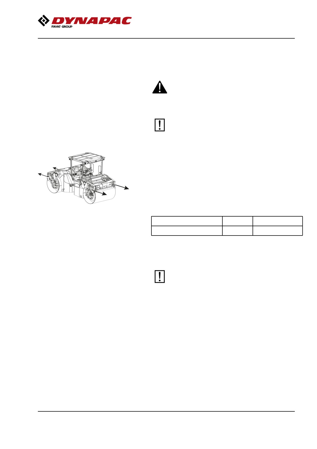
When towing/retrieving a machine, the towing device
must be connected to both lifting holes in the diagram.
The load is uniformly divided between the two lugs.
Note! Towing in only one hole is not permitted.
The pulling forces should act parallel to the machine's
longitudinal axis, as shown in the figure. See table
Fig. Towing
below for maximum permitted pulling force.
Model
kN
lbf
CC4000-6200
190
42 750
Reverse the towing preparations made to the
hydraulic pump and/or the motor.
101
Miscellaneous
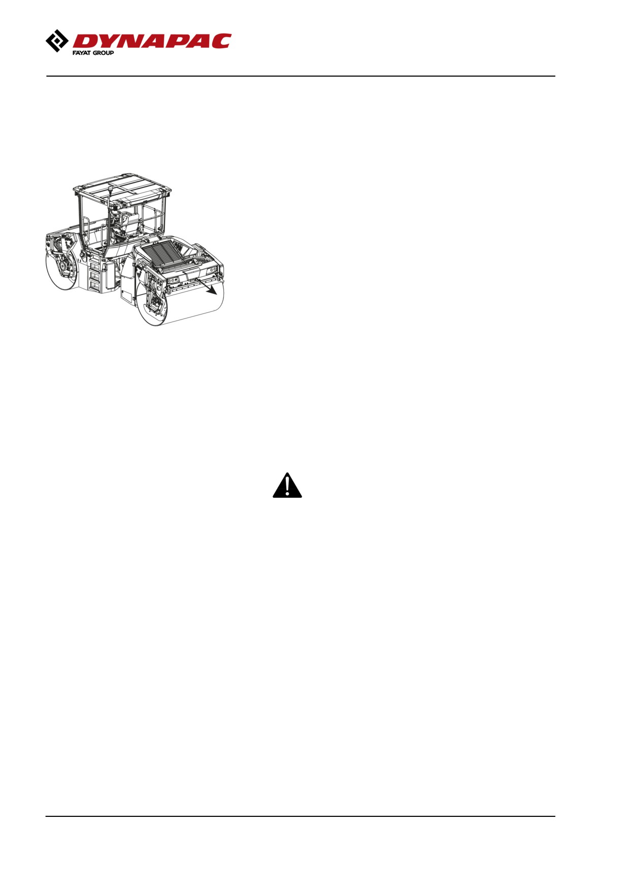
Towing eye
The roller may be fitted with an additional towing eye,
which must not be used for retrieval (max. permitted
pulling force 3000 kg (6 600 lb)).
Be sure to follow local traffic rules.
Fig. Towing eye
Transport
Tie-down and secure the machine according to the
Cargo Securing Certificate for the specific machine if
this is avaliable and applicable.
If not, tie down and secure the machine according to
the cargo securing rules that are valid for the country
where the transport takes place.
Never lash over the machine’s articulated joint, nor
over the machine’s operator platform.
Before securing the machine ensure that :
• the parking brake is applied and in good working condition
• the articulated joint is in closed position
• the machine is centered laterally on the platform
• the lashings are in good condition and fulfills the
corresponding rules for transport securing.
102
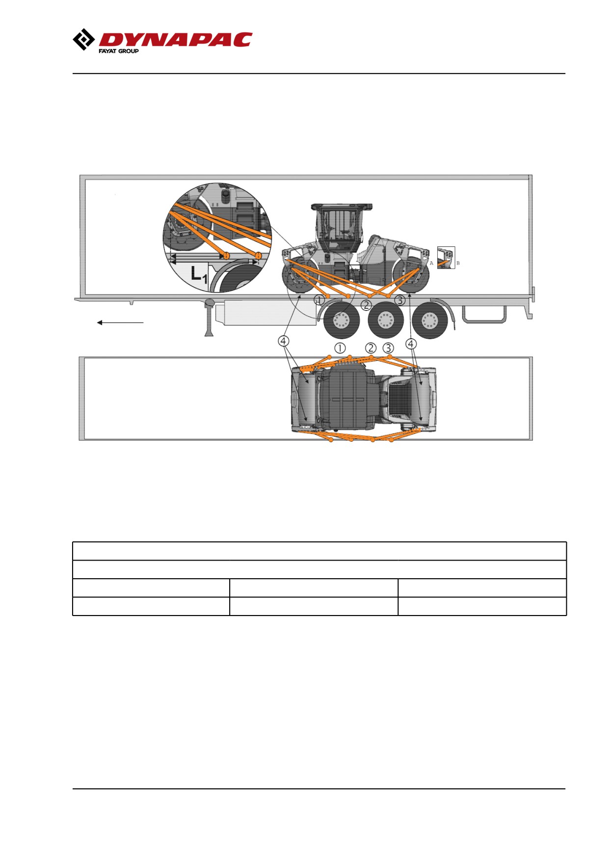
Miscellaneous
Loading CC4000 VI-CC6200 VI and
CO4000 VI-CO6200 VI
Securing vibratory roller CC4000 VI-CC6200 VI and
CO4000 VI-CO6200 VI from Dynapac for transport.
(The instructions also apply to Combi machines)
Roller loaded in
forward
direction
Alternative
Direct of travel
1 - 3
= double lashings, i.e. one lashing with two parts attached to two different lashing points, on
thetrailer, symmetrically placed on the right and left side
4
= rubber
The lashings' permitted distance interval in meters
(1 - 3: Double lashings, LC at least 1.7 tonnes (1700 daN), STF 300 kg (300daN))
Double L1
Double L2
Double L3
0,7 - 2,5
0,9 - 2,5
0,3 - 2,5
For lashing 1 isL1the distance between the lashing point on the edge of the platform and the point directly sideways
from the lashing point on the roller perpendicular to the platform edge.L2 och L3for lashing 2 and 3 the relationship is
the same.
103
Operating instructions - Summary
Load carrier
-
When loaded, the vibratory roller is centered laterally on the platform (± 5 cm).
-
The parking brake is applied and in good working condition, and the articulated joint lock is
closed.
-
The drums are placed on rubber liners, so that the static friction between the surfaces is at
least 0.6.
-
The contact surfaces must be clean, wet or dry, and free from frost, ice and snow.
-
The lashing mounts on the load carrier have LC/MSL at least 2 tonnes.
Lashings
-
The lashings comprise a lashing strap or chain with a permitted load (LC/MSL) of at least 1.7
tonnes (1,700 daN) and a pre-tension STF of at least 300 kg (300 daN). The lashings are
re-tightened as required.
-
Each of lashings 1-3 is either a double or two single lashings. A double lashing runs in a sling
through a lashing point or around a machine part and down into two different fasteners on the
platform.
-
Lashings in the same direction are placed in different lashing mounts on the trailer. Lashings
that are pulled in opposite directions may be placed in the same lashing mount, however.
-
The lashings are as short as possible.
-
The lashing hooks must not lose grip if the lashings become slack.
-
The lashings are protected against sharp edges and corners.
-
The lashings are located symmetrically in pairs on the right and left sides.
104
Operating instructions - Summary
Operating instructions - Summary
1.
Follow the SAFETY INSTRUCTIONS specified in the Safety Manual.
2.
Make sure that all instructions in the MAINTENANCE section are followed and the
steering hitch lock is unlocked.
3.
Turn the master switch to the ON position.
4.
Move the forward/reverse lever to the NEUTRAL position. Sit down in the seat.
5.
Engage the parking brake.
6.
Disengage the emergency stop. The roller is always starting in transportation
mode.
7.
Set the rpm switch in position idle (LO).
8.
Start the engine and allow it to warm up.
9.
Set the rpm switch in position working speed (HI) or (ECO).
10. Disengage the parking brake.
11. Drive the roller. Operate the F/R lever with care.
12. Test the brakes. Remember that the braking distance will be longer if the
hydraulic fluid is cold.
13. Set the transportation/working mode button in position working mode.
14. Use vibration only when the roller is in motion.
15. Check that the drums are thoroughly watered when watering is required.
16. IN AN EMERGENCY:
- Press the EMERGENCY STOP.
- Hold the steering wheel firmly.
- Brace yourself for a sudden stop.
17. When parking:
- Activate the parking brake.
- Switch off the engine and block the drums if the roller is on an inclined surface.
18. When lifting: - Refer to the relevant section in the Instruction Manual.
19. When towing: - Refer to the relevant section in the Instruction Manual.
20. When transporting: - Refer to the relevant section in the Instruction Manual.
105
Operating instructions - Summary
21. When recovering - Refer to the relevant section in the Instruction Manual.
106
Preventive maintenance
Preventive maintenance
Complete maintenance is necessary for the machine
to function satisfactorily and at the lowest possible
cost.
The Maintenance section includes the periodic
maintenance that must be carried out on the machine.
The recommended maintenance intervals assume that
the machine is used in a normal environment and
working conditions.
Acceptance and delivery inspection
The machine is tested and adjusted before it leaves
the factory.
On arrival, before delivery to the customer, delivery
inspection must be conducted as per the check list in
the warranty document.
Any transport damage must be reported immediately
to the transport company, as this is not covered by the
product warranty.
Warranty
The warranty is only valid if the stipulated delivery
inspection and the separate service inspection have
been completed as per the warranty document, and
when the machine has been registered for starting
under the warranty.
The warranty is not valid if damage has been caused
by inadequate service, incorrect use of the machine,
the use of lubricants and hydraulic fluids other than
those specified in the manual, or if any other
adjustments have been made without the requisite
authorization.
107
Preventive maintenance
CALIFORNIA
Proposition 65
Decal and location of decal shown in section
Machine description.
108