Altivar 212 Variable speed drives for synchronous and asynchronous motors. Programming Manual (2014) - page 5
Functions for Scroll
Driving Scroll (F324)
This section will regroup basics parameters to ensure a good control and performance for the [Driving Scroll] (F324).
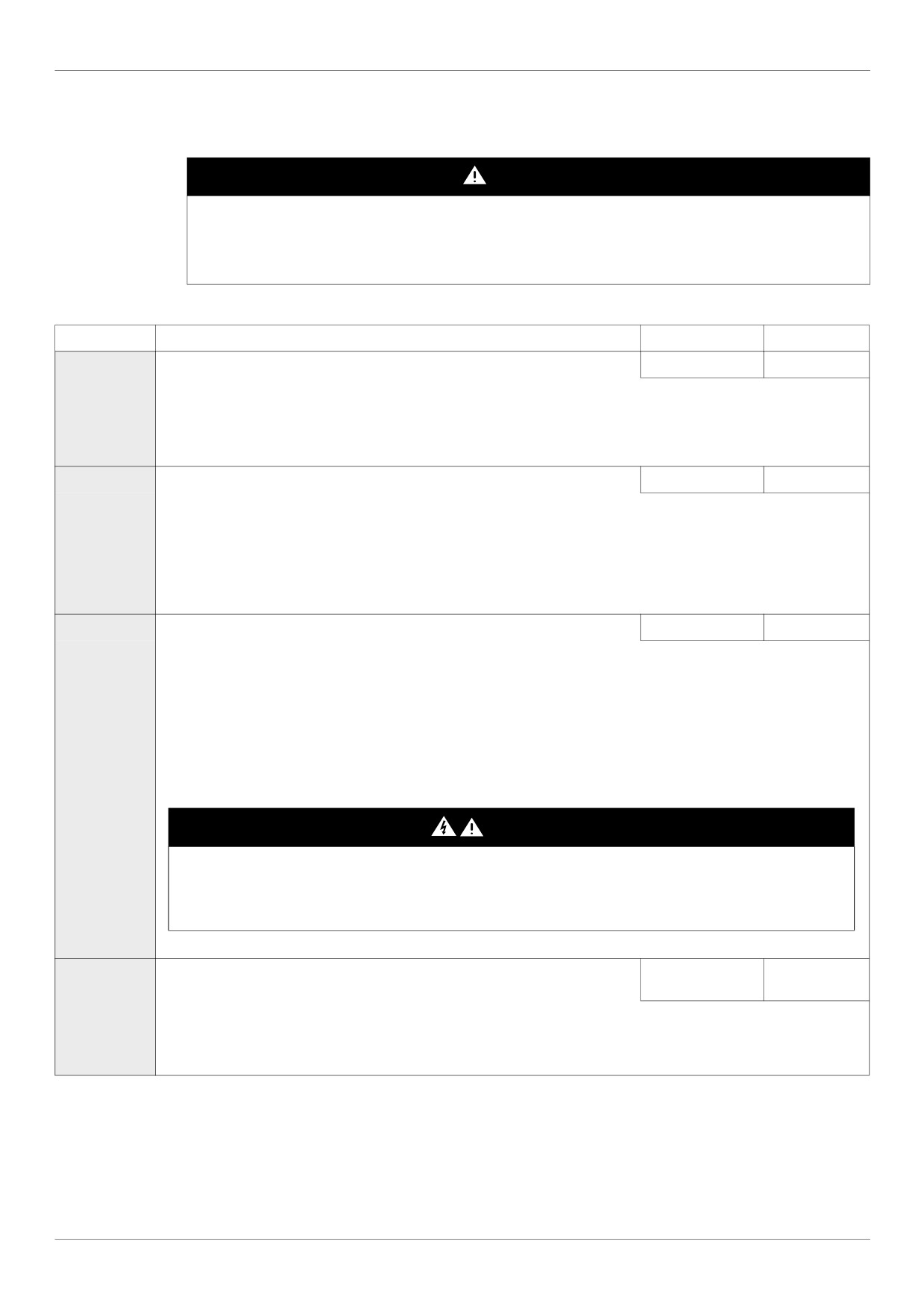
DANGER
UNINTENDED EQUIPMENT OPERATION
Enabling Driving Scroll parameter (F324) will modify the setting of some parameters (see page 159). All previous setting of
these parameters will be lost.
• Modify only these parameters after activation of Driving Scroll parameter (F324).
Failure to follow these instructions will result in death or serious injury.
Code
Name / Description
Adjustment range
Factory setting
F324
[Driving Scroll]
Driving a Scroll Compressor
-
0
Motor characteristics and control parameters.
0
[No]
1
[Yes]
Automatic values of parameters changes when F324 changes from 0 to 1, see the table page 159
F311
[Motor direction]
-
1 [FW only]
If [Driving Scroll] (F324) page 160 is set to [yes] (1) the setting is replaced by [FW only] (1).
(1)
Use parameter F311 to permit only forward or reverse operation.
0
[Fw & Rev.]
1
[Fw only]
2
[Rev. only]
Pt
[Mot cont. mode sel.] Motor control mode
-
1
(1)
If [Driving Scroll] (F324) page 160 is set to [yes] (1) the setting is replaced by [SVC] (3).
0
[Constant V/Hz]: Constant V/Hz
1
[Variable Torque]: Variable torque
2
[Cst V/Hz+Boost]: Constant V/Hz with automatic torque boost
3
[SVC]: Sensorless vector control
4
[Economy]: Energy saving
5
[Do not use]: Reserved
6
[PM Control]: Permanent Magnet Motor Control Law
DANGER
HAZARD OF ELECTRIC SHOCK, EXPLOSION OR ARC FLASH
If [Mot cont. mode sel.] (Pt) is set to (6) (Permanent Magnet Motor Control Law), output phase loss monitoring, while the motor
is running, is disabled. Phase loss and, by implication, accidental disconnection of cables, are not detected.
Verify that this behavior does not result in unsafe conditions and implement alternative monitoring function if required.
Failure to follow these instructions will result in death or serious injury.
uLu
[Motor Rated Voltage]
According to drive
According to
rating (2)
drive rating (2)
Set parameter uLu (vLv) to the motor’s rated voltage as indicated on the motor nameplate.
ATV212pppM3X: 50...330 V.
ATV212pppN4: 50...660 V
Note: Drive output voltage cannot be set to exceed the input line voltage level.
(1) When (F324) changes from [No] (0) to [Yes] (1), some of linked parameters are set to a new value.
When (F324) changes from [Yes] (1) to [No] (0), linked parameters value are not changed.
(2) See table page 199
160
Functions for Scroll
uL
[Motor rated freq.]
25...400 Hz
50.0 Hz
(1)
If [Driving Scroll] (F324) page 160 is set to [yes] (1) the setting is replaced by 50.0 Hz.
Set parameter uL(vL) to the motor’s rated frequency as indicated on the motor nameplate.
Note: It is possible to set the drive’s various motor control frequencies to 50 Hz by setting [Parameter reset] (tYP) to 1, the
50 Hz reset. For more information, see page 66.
F415
[Motor rated current]
0.1 to 200.0 A
According to
drive rating (2)
Set parameter F415 to the motor rated current in amperes as indicated on the motor’s nameplate.
F417
[Motor rated speed]
100.0 to 15000 rpm
According to
drive rating (2)
Set parameter F417 to the motor rated speed in rpm as indicated on the motor’s nameplate.
F601
[Motor Current Limit]
10 to 110% of the
110%
drive’s output cur-
rent rating
(1)
If [Driving Scroll] (F324) page 160 is set to [yes] (1) the setting is replaced by 110%.
NOTICE
RISK OF DAMAGE TO THE MOTOR AND THE DRIVE
Check that the motor will withstand this current.
Check that the profile mission complies with the derating curve given in the installation manual
Failure to follow this instruction can result in equipment damage.
Parameter F601 can be adjusted to limit current during motoring or braking.
Display in Current Limit Mode:
When the drive goes into current limit mode, it will:
Adjust the output frequency to limit the flow of motor current (down when motoring, up when braking).
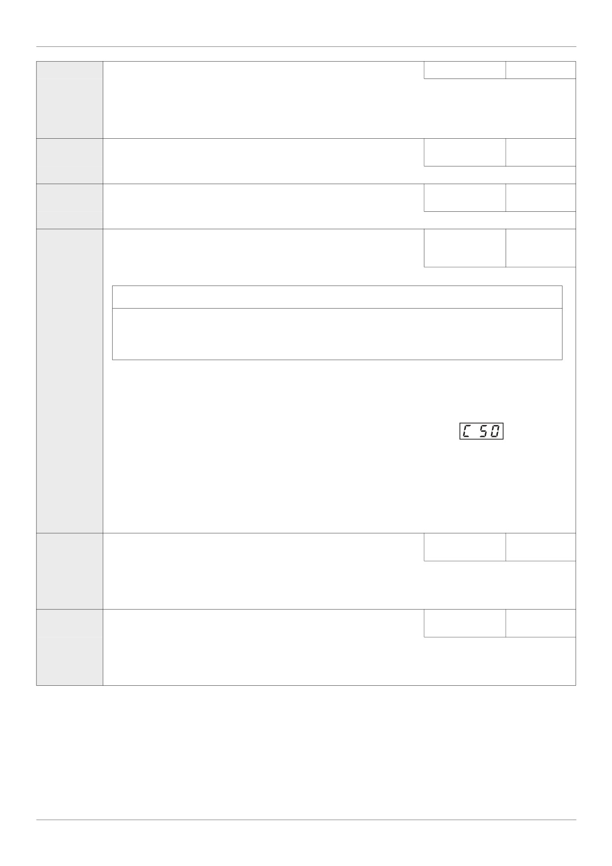
Display the letter C and the output frequency flashing on the embedded software terminal, ex:
If parameter [Unit value selection] (F701) is set to 1 (see page 130), parameter F601 will be adjusted in amperes. If param-
eter F701 is set to 0, parameter F601 will be adjusted as a percentage of the drive’s output rated current as listed on its
nameplate.
The setting of parameter [Switch. freq. level] (F300)
(see page 95) does not change the drive’s rated current for the sake of
this calculation.
Do not set parameter F601 below the no-load current rating of the motor.
LL
0.0 to [Upper limit
[Low limit frequency] Low speed
0.0 Hz
freq] (UL) Hz
(1)
If [Driving Scroll] (F324) page 160 is set to [yes] (1) the setting is replaced by 30%.
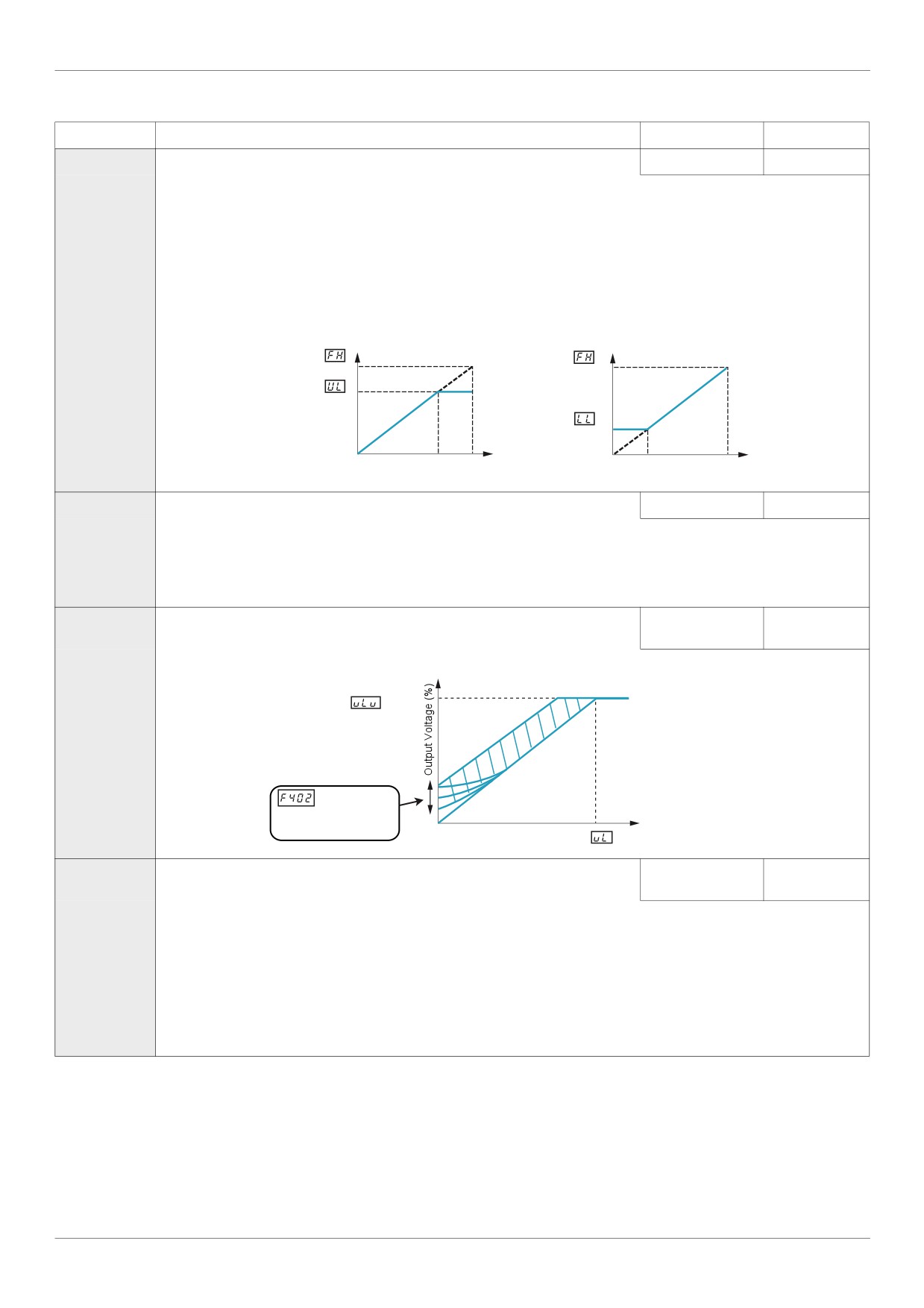
Parameter LL sets the minimum frequency that can be commanded to the drive by the local or remote speed reference source.
See diagram above.
UL
0.5 to [Max fre-
[Upper limit freq]
High speed
50 Hz
quency] (FH) Hz
(1)
If [Driving Scroll] (F324) page 160 is set to [yes] (1) the setting is replaced by 90%.
Parameter UL sets the maximum frequency that can be commanded to the drive by the local or remote speed reference source.
The top end of its range is limited by the setting of Maximum frequency [Max frequency] (FH). See diagram above.
(1) When (F324) changes from [No] (0) to [Yes] (1), some of linked parameters are set to a new value.
When (F324) changes from [Yes] (1) to [No] (0), linked parameters value are not changed.
(2) See table page 199
161
Functions for Scroll
Code
Name / Description
Adjustment range
Factory setting
FH
[Max frequency]
Maximum Frequency
30.0 Hz to 400.0 Hz
50.0 Hz
(1)
If [Driving Scroll] (F324) page 160 is set to [yes] (1) the setting is replaced by 90%.
The setting of parameter FH determines the maximum output frequency of the drive.
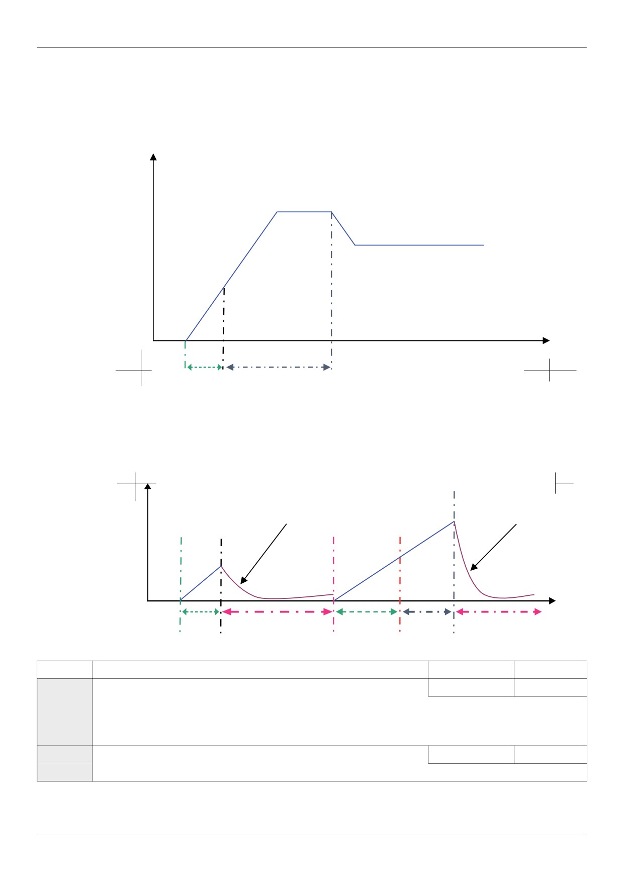
FH limits the setting of parameter [Upper limit freq] (UL) (see page 92), which can be adjusted while the drive is operating.
Acceleration and deceleration rates are also affected by the setting of FH, as the definition of [Acceleration time 1] (ACC) or
[Deceleration time 1] (dEC) (see page 162) is the time it takes for the drive to ramp the motor up or down between zero speed
and the setting of FH.
FH can only be adjusted while the drive is stopped.
Output frequency (Hz)
Output frequency (Hz)
0
0
Speed reference
100%
Speed reference
100%
F401
[Slip Compensation]
0 to 150%
50 %
(1)
If [Driving Scroll] (F324) page 160 is set to [yes] (1) the setting is replaced by 0%.
Before adjusting parameter F401, verify that parameter [Motor rated speed] (F417) (see page 161) is set to the rated speed
of the motor in rpm. Parameter F401 can be used to fine-tune the drive’s slip compensation feature. Increasing the value of
parameter F401 increases the drive’s compensation of motor slip.
F402
[Auto Torque Boost]
0.0 to 30.0%
According to
drive rating (2)
Use parameter F402 to adjust the amount of automatic torque boost that is applied.
Motor rated voltage
: Automatically
adjusts the
amount of
0
torque boost.
Motor Rated Frequency
Output Frequency (Hz)
dEC
[Deceleration time 1]
0.0 to 3200 s
According to
drive rating (2)
(1)
If [Driving Scroll] (F324) page 160 is set to [yes] (1) the setting is replaced by 0.9 s.
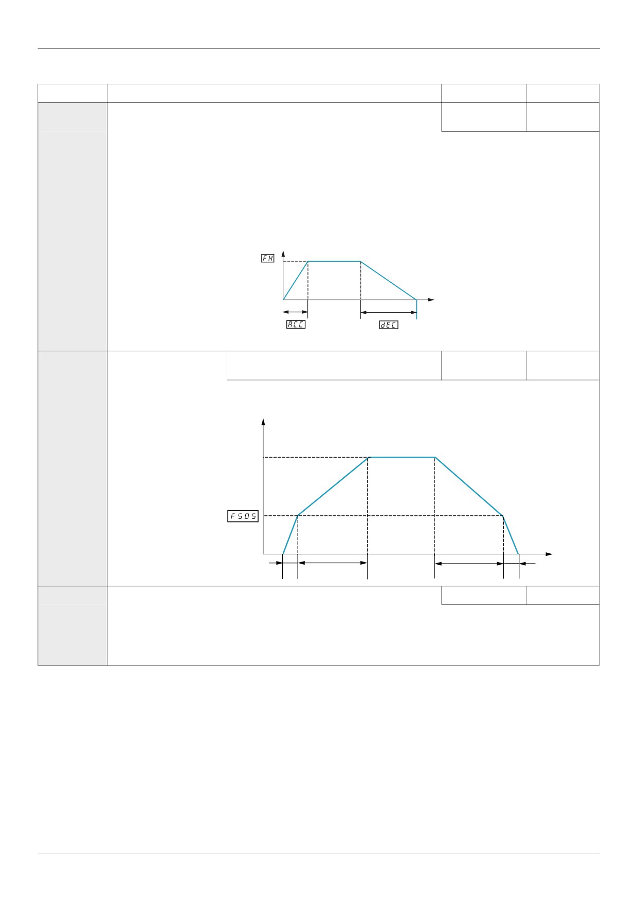
The setting of parameter dEC determines the slope of the deceleration ramp and the time it takes for the output frequency of
the drive to decrease from the setting of [Max frequency] (FH) to 0 Hz.
If parameter [Auto ramp] (AU1) is set to 1, the deceleration ramp may be increased or decreased from the setting of dEC,
depending on the amount of load on the motor during ramp down. See diagram above.
If two different deceleration rates are needed, see parameter [Deceleration time 2] (F501) on page 93.
(1) When (F324) changes from [No] (0) to [Yes] (1), some of linked parameters are set to a new value.
When (F324) changes from [Yes] (1) to [No] (0), linked parameters value are not changed.
(2) See table page 199
162
Functions for Scroll
Code
Name / Description
Adjustment range
Factory setting
ACC
[Acceleration time 1]
0.0 to 3200 s
According to
drive rating (2)
(1)
If [Driving Scroll] (F324) page 160 is set to [yes] (1) the setting is replaced by 0.9 s.
The setting of parameter ACC determines the slope of the acceleration ramp and the time it takes for the output frequency of
the drive to increase from 0 Hz to the setting of [Max frequency] (FH) (see page 162).
If parameter [Auto ramp] (AU1) (see page 95) is set to 1 or 2, the acceleration ramp may be increased or decreased from the
setting of ACC, depending on the amount of load on the motor during ramp up.
If two different acceleration rates are needed, see parameter [Acceleration time 2] (F500) on page 93.
Output frequency (Hz)
0
Time (S)
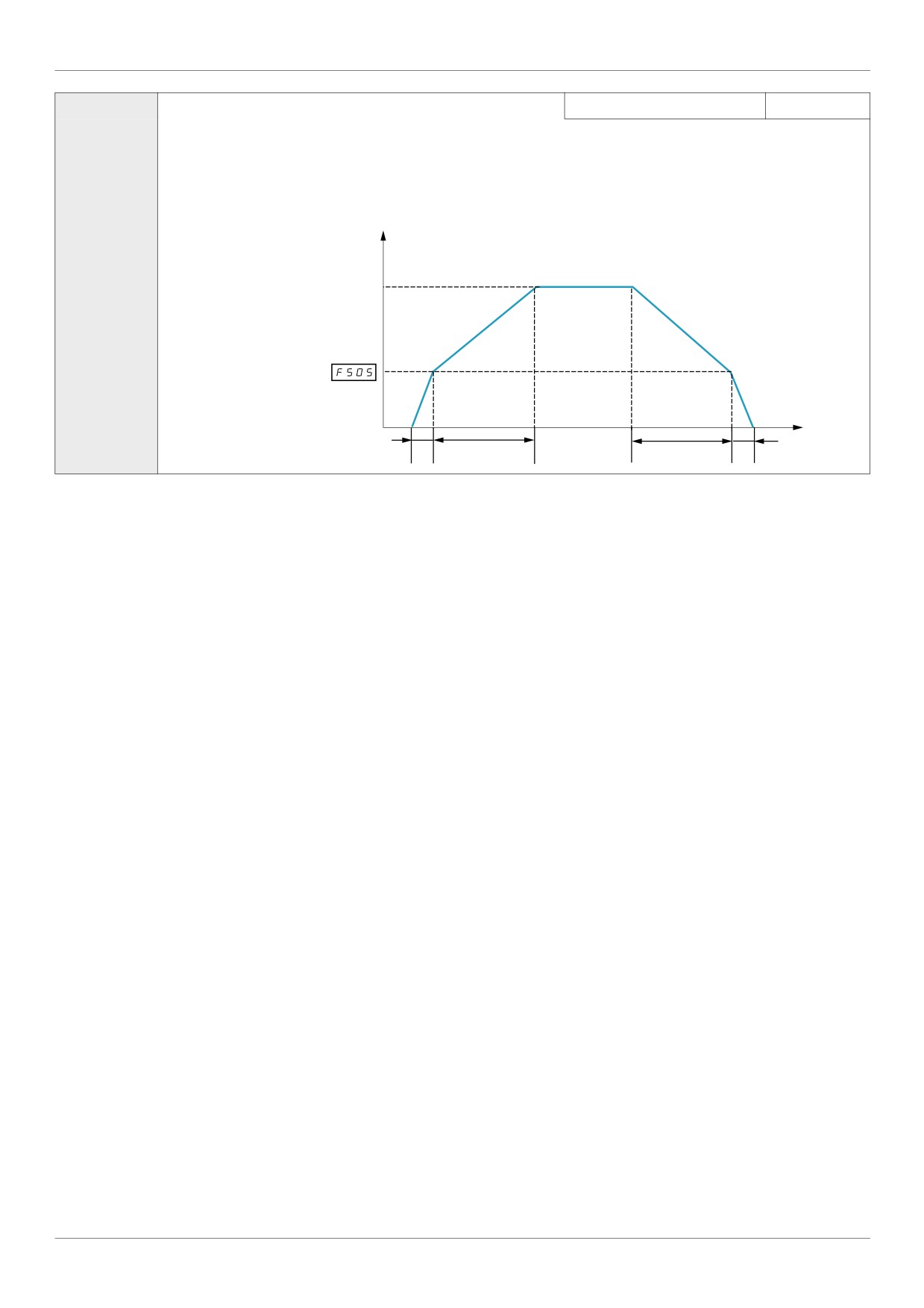
F505
[Commut. ramp freq.]
Acc/Dec pattern switching frequency
0.0 to [Upper limit
0.0 Hz
freq] (UL) (Hz)
If parameter F505 is set to a frequency greater than 0.0, the drive will use Acc/Dec pattern 1 above that frequency and Acc/Dec
pattern 2 above.
Output Frequency (Hz)
Speed Reference
(1) ACC Acceleration Slope
(2) F500 Acceleration Slope
(3) F501 Deceleration Slope
(4) dEC Deceleration Slope
Time (S)
Acceleration/Deceleration Switching
0
Logic Input
(1)
(2)
(3)
(4)
F501
[Deceleration time 2]
0.0 to 3200 s
20.0 s
Parameter F501 sets the second deceleration time. Switching between deceleration rates 1 and 2 is accomplished by means
of:
- Parameter [Ramp switching] (F504) (see page 95),
- A particular operating frequency (see parameter [Commut. ramp freq.] (F505) above), or
- A logic input assigned to functions 5, 20, 21, 30, 31 - 35, or 40 (see table beginning on page 101).
(1) When (F324) changes from [No] (0) to [Yes] (1), some of linked parameters are set to a new value.
When (F324) changes from [Yes] (1) to [No] (0), linked parameters value are not changed.
(2) See table page 199
163
Functions for Scroll
F500
[Acceleration time 2]
0.0 to 3200 s
20.0 s
Parameter F500 sets the second acceleration time. Switching between acceleration rates 1 and 2 is accomplished by means
of:
Parameter [Ramp switching] (F504) (see page 95),
A particular operating frequency (see parameter [Commut. ramp freq.] (F505) above), or
A logic input assigned to functions 5, 20, 21, 30, 31 - 35, or 40 (see table beginning on page 101)
Output Frequency (Hz)
Speed Reference
(1) ACC Acceleration Slope
(2) F500 Acceleration Slope
(3) F501 Deceleration Slope
(4) dEC Deceleration Slope
Time (S)
Acceleration/Deceleration Switching
0
Logic Input
(1)
(2)
(3)
(4)
164
Functions for Scroll
Driving Scroll (F324) (continued)
Code
Name / Description
Adjustment range
Factory setting
F400
[Auto-tuning drive]
-
0
DANGER
HAZARD OF ELECTRIC SHOCK OR ARC FLASH
During auto-tuning, the motor operates at rated current.
Do not service the motor during auto-tuning.
Failure to follow these instructions will result in death or serious injury.
WARNING
LOSS OF CONTROL
It is essential that the following parameters uLu, uL, F415 and F417 are correctly configured before starting auto-
tuning.
When one or more of these parameters have been changed after auto-tuning has been performed, F400 will return 0
and the procedure will have to be repeated.
Failure to follow these instructions can result in death or serious injury.
NOTICE
RISK OF DAMAGE TO THE MOTOR
Conduct auto-tuning only after the motor has been connected and operation completely stopped.
If auto-tuning is conducted immediately after operation stops, the presence of a residual voltage may result in abnormal
tuning.
Failure to follow these instructions can result in equipment damage.
Auto tuning enable
0
[Disabled]
1
[Initialize constant]:
Factory setting of [Auto Torque Boost] (F402) for asynchronous motor.
Factory setting of [Auto Torque Boost] (F402) , [Autotune L q-axis] (F912), and [Autotune L q-axis] (F913), and
[Motor Rated Voltage] (vlv) for synchronous motor.
2
[Tun Static]:Tune Dynamic, with driving run after the tuning.
Application settings of [Auto Torque Boost] (F402) for asynchronous motor.
Application settings of [Auto Torque Boost] (F402) , [Autotune L q-axis] (F912), and [Autotune L q-axis] (F913) for
synchronous motor.
3
[Tun Dyn.]: Complete tune Dynamic, with driving run after the tuning.
Application settings of [Auto Torque Boost] (F402) , [Autotune L q-axis] (F912), [Autotune L q-axis] (F913), and
[Motor Rated Voltage] (vlv) for synchronous motor.
4
[Tun Prst 1]: Tune Static, without driving run after the tuning.
Application settings of [Auto Torque Boost] (F402) for asynchronous motor.
Application settings of [Auto Torque Boost] (F402) , [Autotune L q-axis] (F912), and [Autotune L q-axis] (F913) for
synchronous motor.
5
[Tun Prst 2]: Complete tune Static, without driving run after the tuning.
Application settings of [Auto Torque Boost] (F402) , [Autotune L q-axis] (F912), and [Autotune L q-axis] (F913), and
[Motor Rated Voltage] (vlv) for synchronous motor.
Parameter F400 is reset to “0” after the auto tuning is performed
F458
[Current loop gain]
0...100 Hz
0 Hz
Parameter F458 is set to the response gain of current loop
Note: Contact Schneider electric product support to confirm the modification of this parameter.
165
Functions for Scroll
F418
[Frequency loop gain]
1 to 150
40
Parameters F418 and [Freq. loop stability] (F419) reduce the speed of the drive’s response to a change in speed command.
The factory setting of these two parameters assumes that the inertia of the load is three times as large as that of the motor shaft.
Adjust these two parameters if the factory setting is not appropriate for the application.
Note: It is possible for the drive’s output frequency to exceed its upper limit (parameter [Max frequency] (FH)) if the acceleration
parameter (ACC or F507) is set to its minimum value.
Increasing the setting of parameter F418 reduces the drive’s response time to changes in the speed reference.
F419
[Freq. loop stability]
Frequency loop stability
1 to 100
20
Increasing the setting of parameter F419 further reduces the drive’s response to changes in the speed reference.
F495
[Motor voltage coef.] Maximum voltage adjustment coefficient
90 to 120%
104%
Use parameter F495 to limit the drive’s maximum output voltage. Increasing this setting increases torque when the motor is
operated above its rated frequency, but may also cause motor vibration. Do not increase the value of F495 if motor vibrations
occur.
F915
[PM mode selection] PM control mode selection
-
3
0
[0]: basic control
1
[1]: control type 1 (for IPM)
2
[2]: control type 2 (for IPM)
3
[3]: control type 3 (for IPM / SPM)
4
|4]: control type 4 (for IPM / SPM)
For more details see the chapter Motor Control Parameters “F915” on page 84
F912
[Autotune L q-axis]
Q-axis self-inductance
0.01 to 650 mH
10
Axis "q" stator inductance in mH
The setting is replaced by the result of the auto-tuning operation, if it has been performed.
F913
[Autotune L d-axis]
D-axis self-inductance
0.01 to 650 mH
10
Axis "d" stator inductance in mH
The setting is replaced by the result of the auto-tuning operation, if it has been performed.
F916
[PM Align cur. Level] Stabilization at the starting and low speed (for PM)
0 to 100 %
25 %
It might be able to stabilize the motor rotation behavior by the current in D axis at no load when starting or low-speed
For a complete description, see page 85.
F921
[Init. Pos. Current]
Current for initial position estimation
10 to 150
100 %
During the auto-tuning for d-axis / q-axis inductance, the maximum current level can be adjusted by this parameter setting.
F420
[Torque Boost Coef] Compensation coefficient of torque boost
0 to 200%
90 %
If synchronous or asynchronous motor is used F420 [Torque Boost Coef] is set to 90%.
Note:
If E-20 [Excess torque boost flt] trip occurs at the start, it is recommended to be decreased the setting of F420
166
Functions for Scroll
F130
[RY Relay Function 1] RYA-RYC Relay Function
0 to 69, 254, 255
4
If [Driving Scroll] (F324) page 160 is set to [yes] (1) the setting is replaced by [disable oil injection in high-speed positive logic] (70)
(1)
For a complete description of the various functions assignable to the RYA-RYC relay, see page 108.
The RYA-RYC relay can have a secondary assignment with programmed selection logic. See parameters
[RY Relay Function 2] (F137) and [RY logic select.] (F139) on page 124 for more detail.
F130 - RY Behaviour
+
-
0
Electrovalves
1
0
F132
[FL Relay Function] Delay for RYA-RYC Relay
0 to 69, 254, 255
11
If [Driving Scroll] (F324) page 160 is set to [yes] (1) the setting is replaced by [Inv F101 sp reach] (9)
(1)
This parameter introduces a delay on RYA-RYC output signal relay see page 108.
F132 - FL Behaviour
+
-
0
Electrovalves
1
0
167
Functions for Scroll
0.0 to [Max frequen-
F101
[Freq. 2 reached]
Relay Output - Frequency Level 2 Attained
cy] (FH) Hz
0.0 Hz
If [Driving Scroll] (F324) page 160 is set to [yes] (1) the setting is replaced by 65 Hz.
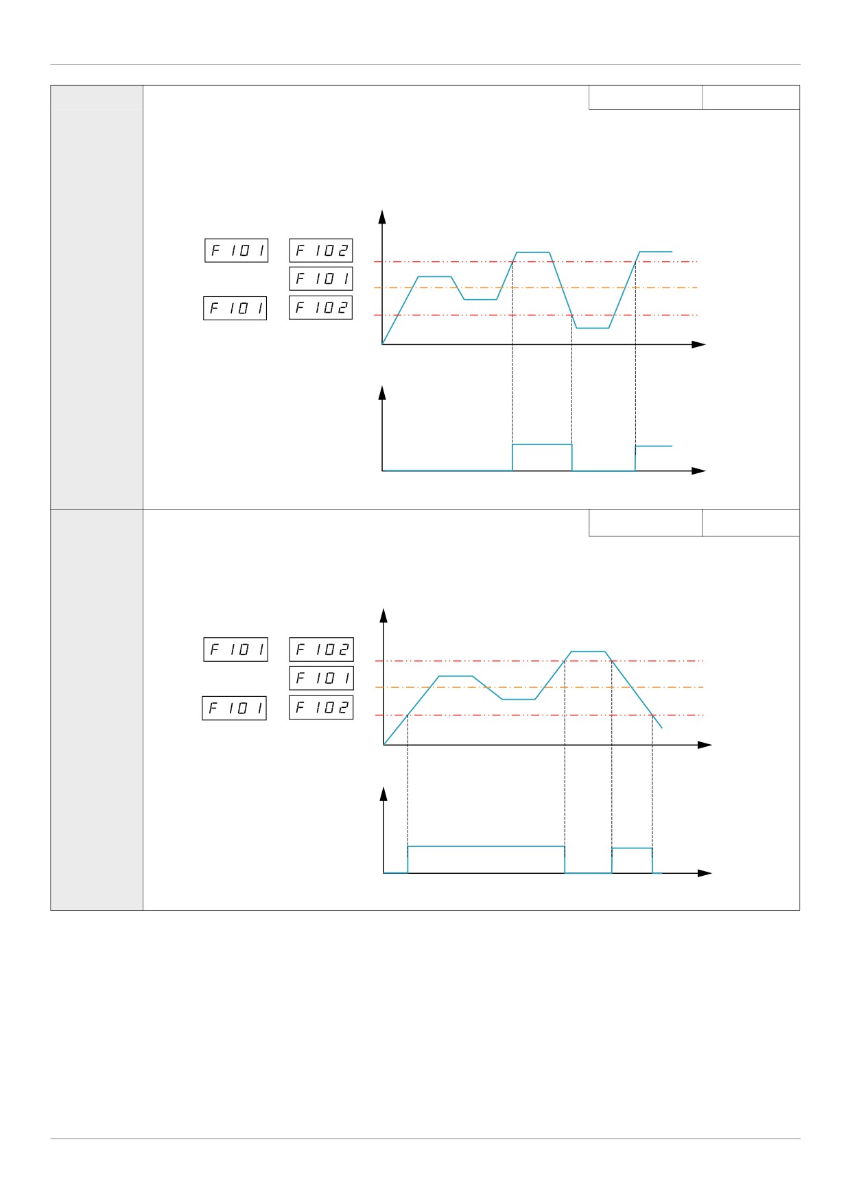
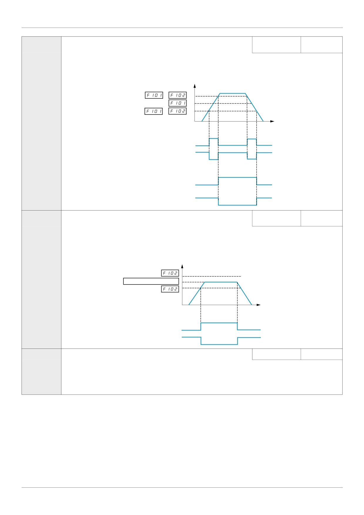
(1)
The frequency set by parameter F101 +/- the [Freq.2 bandw.] (F102) detection band is the threshold level for relay output
functions 8 and 9 and the hysteresis for relay output functions 66 and 67 (see page 113).
Output Frequency (Hz)
+
-
0
Time (S)
ON
Relay Output Function 8
OFF
Relay Output Function 9
ON
OFF
ON
Relay Output Function 66
OFF
Relay Output Function 67
ON
OFF
0.0 to [Max frequen-
F102
[Freq.2 bandw.]
Frequency Attained Detection Band
cy] (FH) Hz
2.5 Hz
If [Driving Scroll] (F324) page 160 is set to [yes] (1) the setting is replaced by 0.65 Hz.
(1)
Parameter F102 determines the bandwidth around the [Freq.2 reached] (F101) frequency (see diagram above) and the
commanded frequency (see diagram below) driving relay output functions 6 through 9 (see page 101).
Output Frequency (Hz)
+
Commanded Frequency
-
0
Time (S)
ON
Relay Output Function 6
OFF
Relay Output Function 7
ON
OFF
F113
[LI RES selection] RES Logic Input Function (2)
0 to 73
10
If [Driving Scroll] (F324) page 160 is set to [yes] (1) the setting is replaced by [Inverse Run permis.] (54).
(1)
The setting of parameter F113 determines the control function of logic input terminal RES.
(1) When (F324) changes from [No] (0) to [Yes] (1), some of linked parameters are set to a new value.
When (F324) changes from [Yes] (1) to [No] (0), linked parameters value are not changed
(2) See table on 101 for a complete list of RES logic inputs assignment
168
Functions for Scroll
F303
[Number auto reset]
0
DANGER
UNINTENDED EQUIPMENT OPERATION
The automatic restart can only be used on machines or installations which do not pose any danger to either personnel or
equipment.
If the automatic restart is activated, the fault relay will only indicate a fault has been detected once the time-out period for
the restart sequence has expired.
The equipment must be used in compliance with national and regional safety regulations
Failure to follow these instructions will result in death or serious injury.
0
Disabled.
1 to 10
Number of clear attempts.
F303 is common and single for all functions
The fault detection codes, which permit this function, are listed on page 135.
169
Functions for Scroll
Pre-start Scroll (F325)
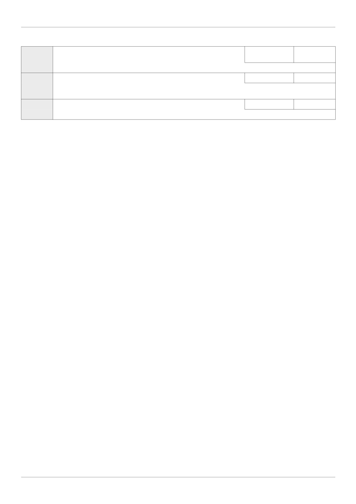
This function is to help protect the compressor. The Drive must reach [Low limit Freq] (LL) within 2 s max. If not,
FreeWheel stop the drive and do an automatic restart after a preset delay [Pre-start delay] (F329). Once [Low limit
Freq] (LL) speed is reached in less than 2 s [LL speed time] (F328) the motor should run at [Pre-Start speed] (F327)
for a [Pre-Start time] (F326) before taking into account the reference frequency.
Speed frequency (Hz)
[Pre-start speed]
(F327)
Reference frequency
[Low limit frequency]
(LL)
Times (s)
[LL speed time]
[Pre-Start time]
(F328)
(F326)
If the [Pre-Start speed] (F327) is never reach, the amount of attempt should be limited at 10, and the alarm code [Auto
reset] (rtrY) should be raised (see alarm codes page 184). After activating this function, [Pre-start Scroll] (F235) must
be achieved at every run order.
Speed frequency (Hz)
[Pre-start speed]
Freewheel Stop
(F327)
Freewheel Stop
[Low limit frequency]
(LL)
Times (s)
(F328)
(F329) and (F303)
(F328)
(F326)
(F329) and (F303)
< x cycles
< x cycles
Code
Name / Description
Adjustment range
Factory setting
F325
[Pre-start Scroll]
Scroll Compressor Pre-start Management
-
0
At every Run Order the Drive must reach a preset Low Limit Frequency within a preset time and a limited number of attempts in order
to avoid mechanical issues.
0
[No]
1
[Yes]
F326
[Pre-Start time]
Time to reach the pre-start speed
0...6000 s
10 s
Time during the motor turn to the pre-start speed
170
Functions for Scroll
F327
[Pre-Start speed]
0.0 Hz to [Upper
50 Hz
limit freq] (UL)
Speed to reach within the pre-start cycle
F328
[LL speed time]
Time to reach LL Freq on pre-start order
0...10 s
2s
Time which needs to be respected for reaching the low limit frequency.
If the motor does not reach the [Low limit frequency] (LL) during this time the motor must stop.
F329
[Pre-start delay]
0...120 s
3s
Delay between two pre-start cycles
171
Functions for Scroll
Std Oiling Cycle (F330)
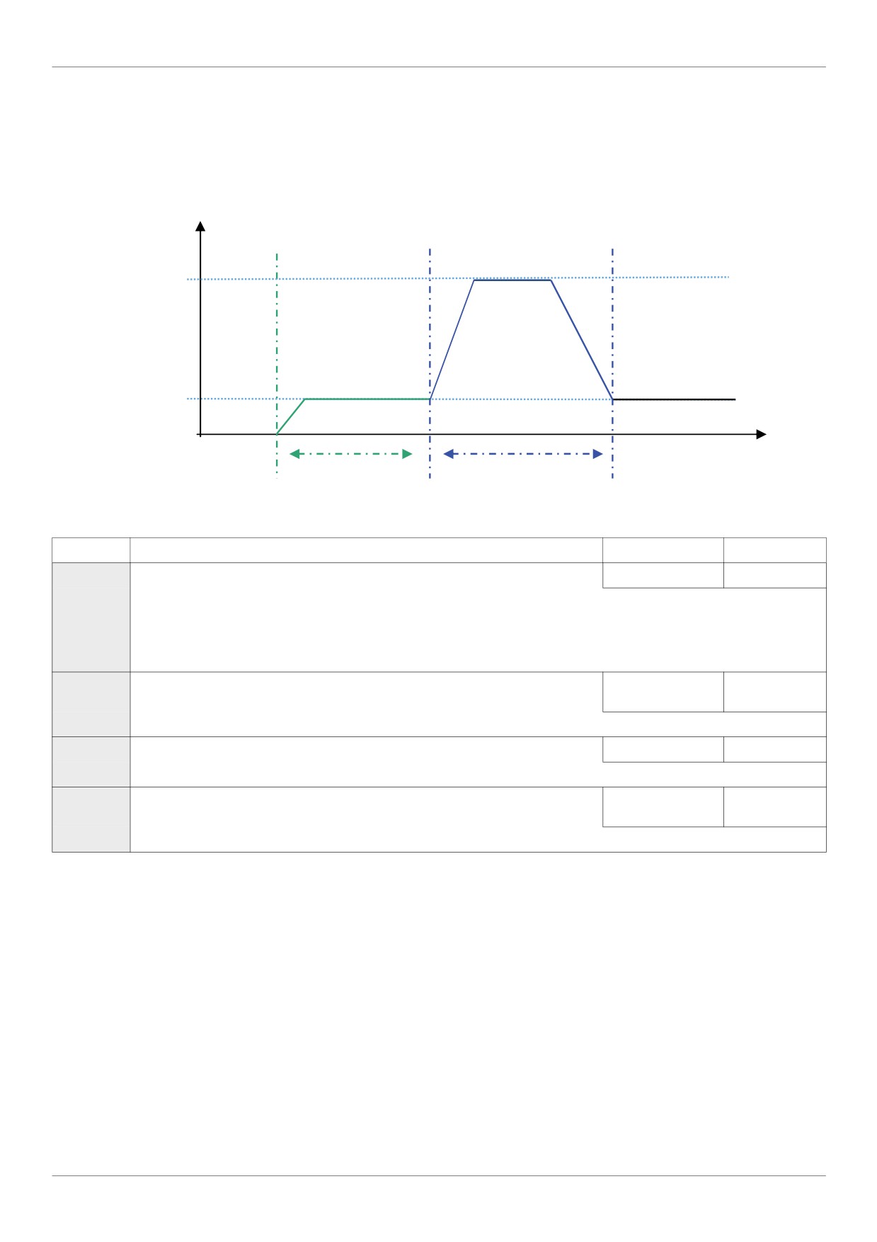
This function helps to prevent the damage to the installation by lubricating it after a period of running. The drive
manages to re-oil the Scroll pump by running the (F330 = [Yes] (1)) motor at the optimal [Std Oiling Speed] (F331)
for a settable [Std Oiling Time] (F332).
The [Std Oiling Speed] (F331) must be reached at least one time within the [Std Oil. Cycle Frq.] (F333) of run order.
Speed (Hz)
[Std Oiling Speed]
(F331)
Drive speed
reference
0
Time (s)
[Std Oil. Cycle Frq.]
[Std Oiling Time]
(F333)
(F332)
Code
Name / Description
Adjustment range
Factory setting
F330
[Std Oiling Cycle]
Periodic Oiling Cycle management
-
0
After a preset period of service and/or a preset time of running at a low speed, the drive must manage an oiling boost cycle by running
at a preset oiling speed during a preset oiling time.
0
[No]
1
[Yes]
F331
[Std Oiling Speed]
Oiling Speed for Std Oiling Cycle
0 Hz to (UL)
70 Hz
[Upper limit freq]
Oiling is done at this frequency.
F332
[Std Oiling Time]
Time to maintain Oiling Speed in Std Cycle
0 s to 6000 s
30 s
Time to maintain oiling speed in standard cycle
F333
[Std Oil. Cycle Frq.]
Frequency (time) of Standard Oiling Cycle
0 to 24 Hours
24 hrs
(of run oder)
Time during the motor which turn without lubrication since the first Run order.
172
Functions for Scroll
Low Speed Oiling (F334)
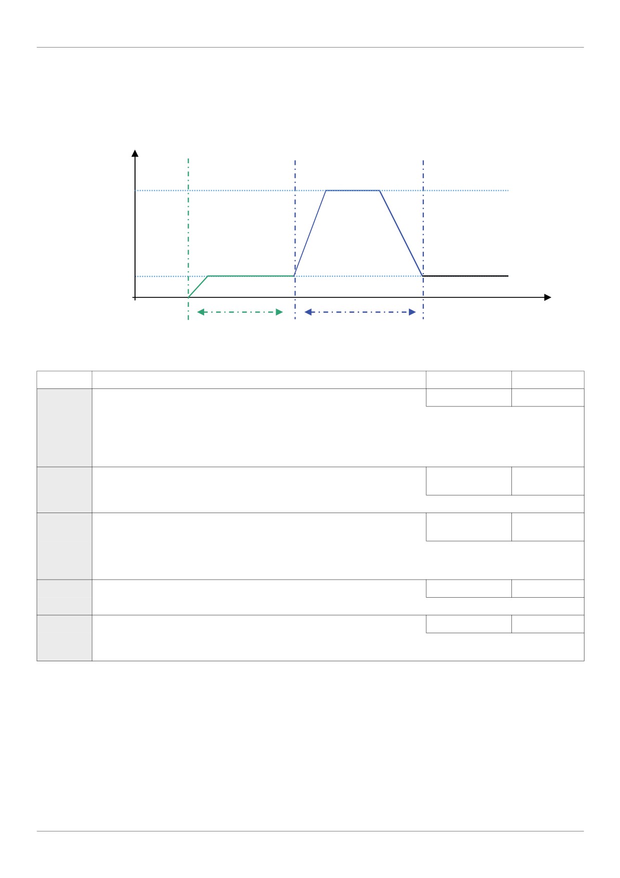
This function helps to protect the installation of low lubrification that occurs at low speed. The [Std Oiling Speed]
(F331) must be reach during a time [Oiling Time at LLS] (F337) if the motor speed stayed under a [LL Speed for
Oiling] (F335) during a cycle limit [LLS Time for Oiling] (F336).
Speed (Hz)
[Std Oiling Speed]
(F331)
[LL Speed for Oiling]
(F335)
0
Time (s)
[LLS Time for Oiling]
[Oiling Time at LLS]
(F336)
( F337)
Code
Name / Description
Adjustment range
Factory setting
F334
[Low Speed Oiling]
Oiling management for low speed running
-
0
A preset oiling speed must be reached during a preset time every time the motor stayed under a preset speed during a preset time
to compensate a too low lubrication due to low speed.
0
[No]
1
[Yes]
F331
[Std Oiling Speed]
Oiling Speed for Std Oiling Cycle
0 Hz to (UL)
70 Hz
[Upper limit freq]
Oiling Speed for Standard Oiling Cycle.
F335
[LL Speed for Oiling]
0 Hz to (UL)
50 Hz
[Upper limit freq]
Low speed threshold to start Oiling control.
If the system never reach it after time [LLS Time for Oiling] (F336) the system will go in lubrification.
F336
[LLS Time for Oiling]
0...360 minutes
60 minutes
Time during the motor turn under the threshold of [LL Speed for Oiling] (F335).
F337
[Oiling Time at LLS]
0...6000 s
30 s
Time to maintain oiling injection in the installation.
173
Functions for Scroll
Scroll Protection (F338)
This function is active only out of the acceleration phase to helps protect the Scroll pump about overloading and
cavitations effect, if the motor current limit is over passed and if the speed is under the [Cavitation Frq.] (F339) the
drive will stop in Freewheel and the alarm signal will be displayed [Cavitation Error] (CAPF).
Code
Name / Description
Adjustment range
Factory setting
F338
[Scroll Protection]
Avoid overloading or cavitation effects
-
0
Scroll compressor protection against the effects of overload and cavitation
If Fire function mode (53) is activated and F338 = (1), [Cavitation Error] (CAPF) alarm signal is inhibited, see Logic input
Functions page 53
0
[No]
1
[Yes]
F339
[Cavitation Frq.]
[Low limit frequency]
30 Hz
(LL) to [Upper limit
freq] (uL)
Cavitation Frequency Threshold.
174
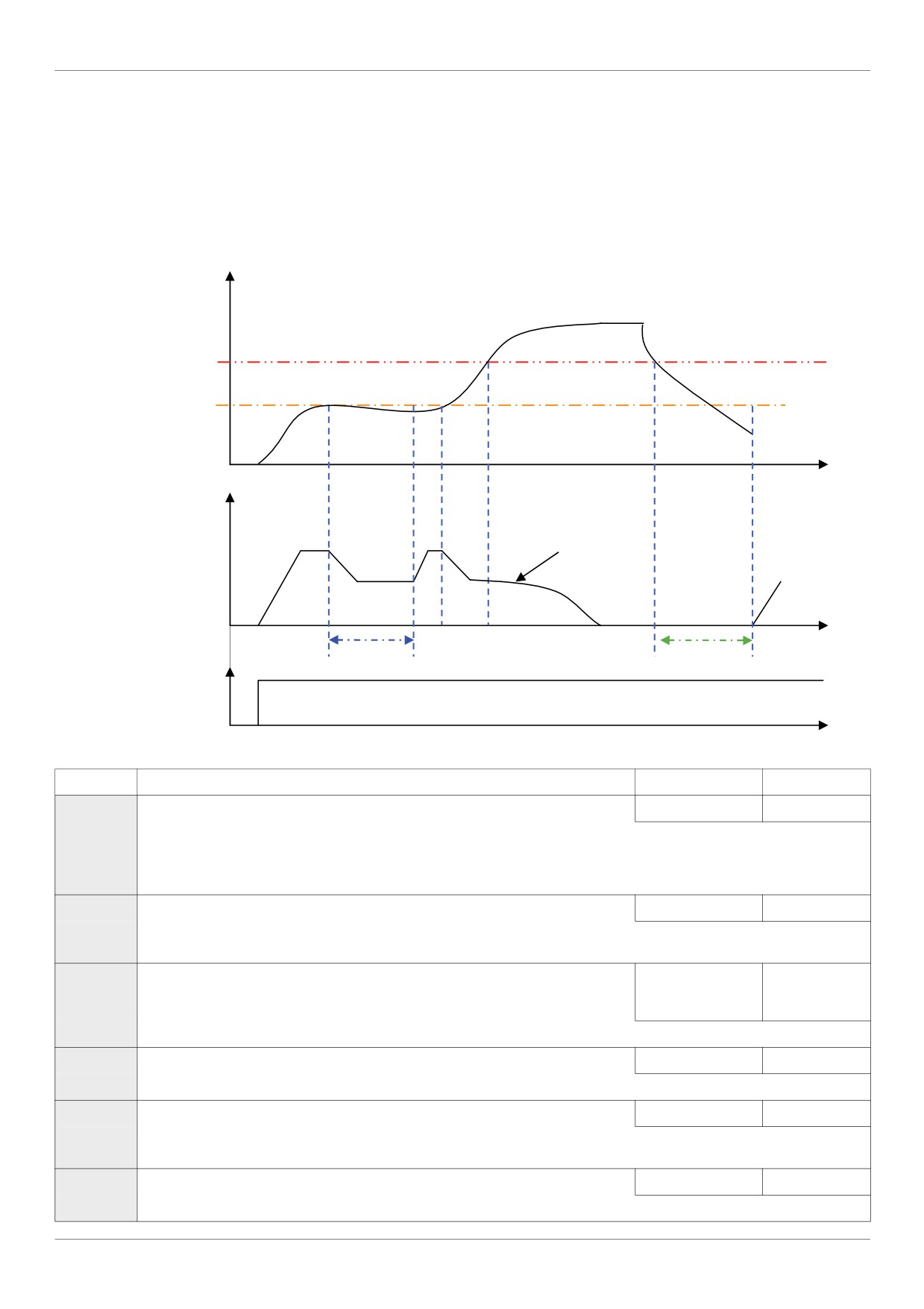
Functions for Scroll
Discharge gas (F349)
This function enables to helps to protect the installation avoiding high temperature or high pressure, the speed will
automatically reduced the speed or stop the Scroll pump depending on temperature level [High Thd] (F350) and [High
high Thd] (F353).
The time [Re-Start Delay] (F354) before automatic restart (see [Number auto reset] (F303) page 169) is settable and
the number of maximum attempt is limited to 10. The restart will come [Re-Start Delay] (F354) after the temperature
gets under y [High high Thd] (F353).
Temperature (%)
[High high Thd] (F353)
[High Thd]
(F350)
T (s)
Speed (Hz)
Stop freewheels
and default trig.
Speed reference
[Cooling Frq.] (F351)
T (s)
RUN Order
[Cooling Time]
[Re-Start Delay]
(F352)
(F354)
1
T (s)
0
Code
Name / Description
Adjustment range
Factory setting
F349
[Discharge gas]
Avoid high temp. or pressure on sensor input
-
0
This function helps to protect the installation avoiding high temperature or high pressure in the refrigerant loop.
0
[No] Function unactive
1
[VIA] Function is active and uses analog input VIA [Ref source VIA]
2
[VIB] Function is active and uses analog input VIB: [Ref source VIB]
F350
[High Thd]
0 - 100
65 %
High Process Threshold
Note: 100% means analog input ports VIA or VIB applied full scale value.
F351
[Cooling Frq.]
[Low limit frequency]
50 Hz
(LL) to [Upper limit
freq] (UL)
Cooling system Frequency.
F352
[Cooling Time]
0 - 30
3 minutes
Time to maintain cooling system frequency.
F353
[High high Thd]
0 - 100
70 %
High high Process Threshold.
Note: 100% means analog input ports VIA or VIB applied full scale value.
F354
[Re-Start Delay]
0...30 minutes
5 minutes
Delay before restart after emergency stop.
175
Functions for Scroll
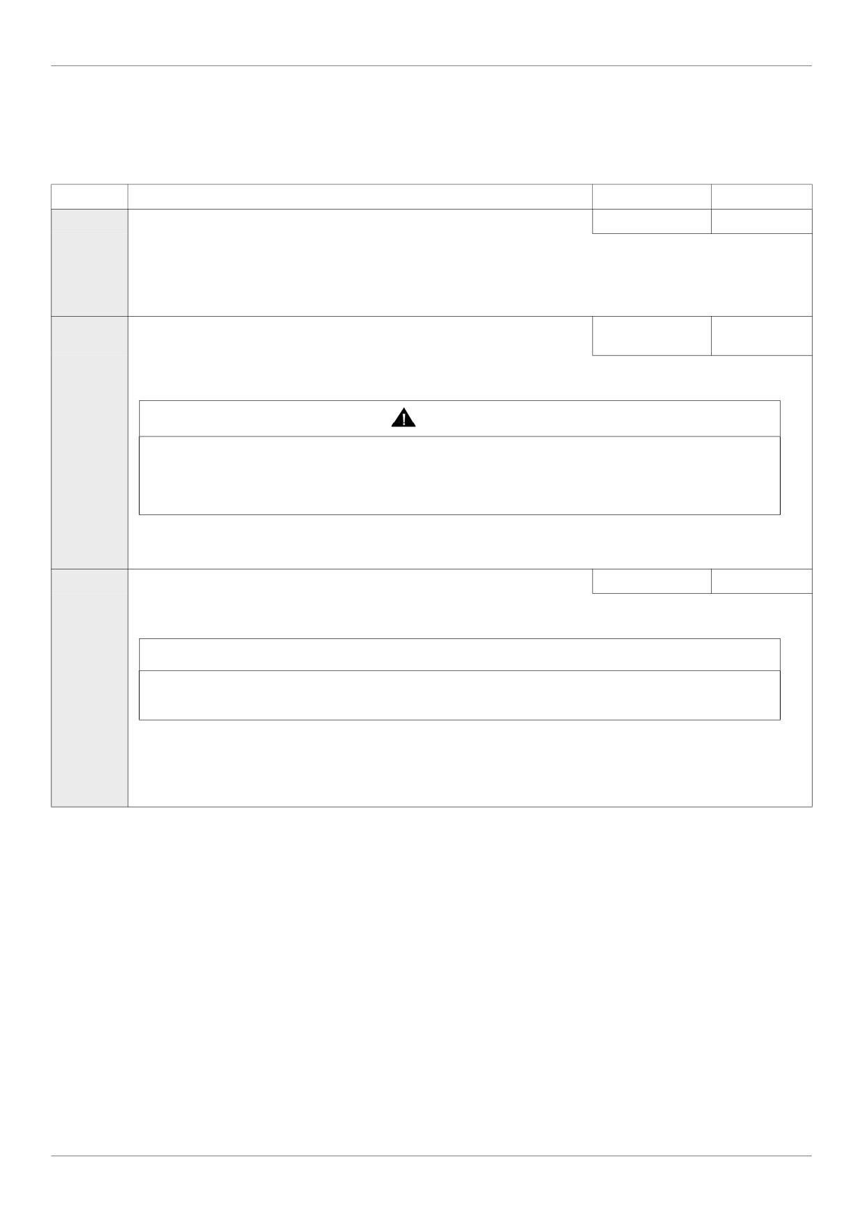
Crankcase heating (F355)
Replace crankcase heaters by using a current injection in motor to generate resistance heating.
Note: Before using the Function [Crankcase heating] (F355), to stop the current injection you should assign a logic
input to Freewheel stop, you can also stop the injection by a power off.
Code
Name / Description
Adjustment range
Factory setting
F355
[Crankcase heating]
Keep the system warm after motor stopped
-
0
Heating by current injection in the motor in order to prevent the emission of gas due to the condensation of the refrigerant into the
compressor.
0
[No]
1
[Yes]
F250
[DC brake start freq.]
0.0 Hz to
0.0 Hz
[Max frequency](FH)
(1)
If [Driving Scroll] (F324) page 160 is set to [yes] (1) the setting is replaced by 0.0 Hz.
WARNING
NO HOLDING TORQUE
DC injection braking does not provide holding torque at zero speed.
DC injection braking does not work when there is a loss of power or when the drive detects a fault.
When necessary, use a separate brake to maintain torque levels.
Failure to follow these instructions can result in death, serious injury, or equipment damage.
When stopping the motor, the drive will apply DC injection braking once the output frequency drops below the level set by parameter
F250.
F251
[DC braking current]
0 to 100 %
50%
(1)
If [Driving Scroll] (F324) page 160 is set to [yes] (1) the setting is replaced by 10%.
NOTICE
RISK OF DAMAGE TO THE MOTOR
Check that the motor will withstand this current without overheating.
Failure to follow this instruction can result in equipment damage.
Parameter F251 sets the level of current applied to the motor during DC injection braking. The displayed value, percent or am-
peres, is set by parameter [Unit value selection] (F701) (see page 130).
During DC injection braking, the drive’s overload protection sensitivity increases. The drive automatically lowers the applied DC cur-
rent to avoid an overload detected fault.
(1) When (F324) changes from [No] (0) to [Yes] (1), some of linked parameters are set to a new value.
When (F324) changes from [Yes] (1) to [No] (0), linked parameters value are not changed.
176
Diagnostics and troubleshooting
Diagnostics and troubleshooting
III
What's in this Part?
This part contains the following chapters:
Chapter
Chapter Name
Page
14
Diagnostics and troubleshooting
179
177
Diagnostics and troubleshooting
178
Diagnostics and troubleshooting
Diagnostics and troubleshooting
15
What's in this Chapter?
This chapter contains the following topics:
Topic
Page
Detected fault conditions
180
Alarm Conditions
184
Pre-alarm Conditions
186
Clearing the detected fault
187
179
Diagnostics and troubleshooting
Detected fault conditions
Refer to tables on pages hereafter to diagnose and solve troubles when there is a fault detection, or when an
alarm, or pre-alarm condition occurs.
If the trouble cannot be solved by the actions described in the tables, contact your Schneider Electric
representative.
DANGER
HAZARD OF ELECTRIC SHOCK, EXPLOSION OR ARC FLASH
• Read and understand the instructions in «Before you begin» chapter, before performing the procedure in
this section.
Failure to follow these instructions will result in death or serious injury.
Alarm Codes
Code
Name
Possible causes
Remedies
CApF
[Cavitation Error]
• Loss of speed due to overload or / and too
• Reduce the load
much torque.
CFI2
[Download transfer
• Invalid configuration.
• Check the configuration loaded previously.
fault]
The configuration loaded in the drive via the
• Load a compatible configuration.
bus or communication network is
inconsistent.
• Transfer using PC soft has not been
• To perform download, uncheck "Display
successful due to rating differences
communication error" (in Tool /
(for example upload of an ATV212pppN4
Environnement option / Startup/Comm.)
configuration to an ATV212pppM3)
E-18
[VIA signal fault]
• The VIA analog signal is below the level set
• Check the signal at VIA and rectify the cause
by parameter F633.
of the signal loss.
• Verify that parameter F633 is set
correctly.
E-19
[CPU communica-
• Communication error between control CPUs
• Check the environment (electromagnetic
tions err.]
Compatibility)
• Turn off and restart product.
• Contact Schneider electric product support.
E-20
[Excess torque boost
• Torque boost parameter
• Repeat the Auto-tuning drive and reduce
flt]
[Auto Torque Boost] (F402) is set too
[Auto Torque Boost] (F402).
high.
• The motor impedance is too low.
During deceleration when
• Set [Auto ramp] (AU1) = (0) [Disabled]
[Mot cont. mode sel.] (Pt) = (1) [Quadr. U/F]
• Decrease the deceleration ramp with
with 3 conditions:
[Deceleration time 2] (F501) and
- Processing for stop
[Commut. ramp freq.] (F505).
- Load current value > 88% x [Motor Current
Limitation] (F601)
- Too slow deceleration, [Max frequency]
(FH) /[Deceleration time 1] (dEC) x 2 msec
< 0.01Hz
E-21
[CPU error 2 fault]
• The control board CPU is inoperable.
• Contact Schneider Electric to repair the
drive.
E-38
[EEprom pwr incom-
• Eeprom power incompatible.
• Contact Schneider Electric to repair the
pat.]
• Product hardware detected fault.
drive.
E-39
[InitPos Det]
• An Error is detected at the starting:
• Check the motor phases and the maximum
The measured current at initial position
current allowed by the drive.
detection at the starting is too small or large
• To check that the inductance of motor is too
according to the inductance of motor or
small or too large.
output phase loss.
EEP1
[EEPROM error 1
• A data writing error has occurred.
• Cycle power to clear the detected fault.
fault]
EEP2
[EEPROM error 2
• Power was removed from the drive during a
• Cycle power to clear the detected fault and
fault]
parameter reset operation resulting in a
try the parameter reset operation again.
data writing error.
• If the detected fault does not clear, contact
• The measured current at initial position
Schneider Electric to repair the drive.
detection at the auto-tuning is too small or
large according to the inductance of motor
or output phase loss
EEP3
[EEPROM error 3
• A data reading error has occurred.
• Cycle power to clear the detected fault.
fault]
180
Diagnostics and troubleshooting
Code
Name
Possible causes
Remedies
EF2
[Ground fault]
• Ground fault in motor or motor cables
• Check the motor and motor cables for
ground faults.
EPHO
[Output phase loss
• Loss of one or more output phases
• Determine the cause of the missing output
fault]
phase (such as a bad connection, an output
disconnect, or an open winding in the motor)
and clear it.
• Check parameter F605.
EPHI
[Input phase loss
• Loss of one input phase
• Determine the cause of the missing input
fault]
phase and clear it.
• Check parameter F608.
EPtF
[Threshold Error]
• Condition for overheating reached,
• Check the system.
exceeded Treshold F353
Err1
[Speed ref. error
• Parameters F202, F203, F210, or
• Set the parameters to the correct settings.
fault]
F212 are set improperly.
Err2
[RAM fault]
• The control board RAM is inoperable.
• Contact Schneider Electric to repair the
drive.
Err3
[ROM fault]
• The control board ROM is inoperable.
• Contact Schneider Electric to repair the
drive.
Err4
[CPU fault 1]
• The control board CPU is inoperable.
• Contact Schneider Electric to repair the
drive.
Err5
[Com RJ45 fault]
• Serial communication error
• Check network control devices and cables.
• Check the setting of the communication
timeout parameter, F803.
• Check the remote graphic display option
cable.
• Check the setting of F829 parameters.
Err7
[Current sensor fault]
• A motor current sensor is inoperable.
• Replace the drive.
Err8
[Network error fault]
• Network communication error
• Check the network control devices and
cables.
Err9
[Remote keypad
• Graphic display option cable disconnected
• Check the RJ45 cable.
fault]
Etn1
[Auto-tuning fault]
• Parameters F401 to F494 are
• Set parameters F401-F494 correctly.
incorrectly set.
• Use a larger drive.
• The motor is too large for the drive.
• Use a larger gauge motor cable.
• The motor cable gauge is too small.
• Verify that the motor is stopped before
• The motor is still rotating at the start of the
starting an auto-tune.
auto-tune.
• Use the drive to power only a 3-phase
• The drive is not powering a 3-phase
induction motor.
induction motor.
• The measured current at initial position
detection at the auto-tuning is too small or
large according to the inductance of motor
or output phase loss
EtYP
[Drive fault]
• The main control board is inoperable.
• Set parameter [Parameter reset] (tYP) to
6.
• If this does not clear the detected error,
replace the drive.
Fd1
[Closed damper 1
• Damper is locked in closed position.
• Set [Damper flt behavior] (F583) to 0.
fault]
• Check the FL relay connection (FLA/FLB).
• Check the relay configuration
(F130/F132).
Fd2
[Closed damper 2
• Damper blocked open or soldered.
• Set [Damper fdb type] (F580) to 0 or
fault]
1.Check the FL relay connection
(FLA/FLB).
• Check the relay configuration
(F130/F132).
M020
[Total input power]
• The accumulated input power value is more
• Clear the accumulated input power value
than 999.999 kWh.
using logic input function 51, or parameter
F748.
181
Diagnostics and troubleshooting
Code
Name
Possible causes
Remedies
OC1
[Overcurrent
• The acceleration time is too short.
• Increase the acceleration time parameters
acceleration]
• The setting of parameter [Mot cont. mode
(ACC or F500).
sel.] (Pt) is incorrect.
• Select the correct setting for parameter [Mot
• The drive is starting into a rotating load.
cont. mode sel.] (Pt).
• The drive is powering a low impedance
• Enable catch on the fly, parameter F301.
motor.
• Adjust the switching frequency parameter
• Ground fault
F300.
• Set parameter F316 to 1 or 3.
OC1P
[SC or ground fault
• Short circuit or ground fault during
• Using a 1000 V testing tool megger, check
acc.]
acceleration
the motor and motor cables for ground faults.
OC2
[Overcurrent
• The deceleration time is too short.
• Increase the deceleration time parameters
deceleration]
• Ground fault
(dEC or F501).
• Set parameter F316 to 1 or 3.
OC2P
[SC or ground fault
• Short circuit or ground fault during
• Using a 1000 V megger, check the motor and
dec.]
deceleration
motor cables for ground faults.
OC3
[Overcurrent cont.
• Abrupt fluctuations in load
• Reduce the load fluctuations.
speed]
• Abnormal load condition
• Check the load.
• Set parameter F316 to 1 or 3.
OC3P
[SC/ground flt cont.
• Short circuit or ground fault during constant
• Using a 1000 V megger, check the motor and
spd]
speed operation
motor cables for ground faults.
• The drive cooling fan is not working.
• Check the fan operation
OCA
[SC inverter at start]
• Ground fault
• Using a 1000 V megger, check the motor and
motor cables for ground faults.
OCL
[SC mot. cable at
• Phase to phase output short circuit
• Using a 1000 V megger, check the motor and
start]
• The motor impedance is too low.
motor cables for ground faults.
OH
[Drive
• The drive cooling fan is not working.
• Restart operation by resetting the drive
overtemperature]
• The ambient temperature is too high.
detected fault after cool-off.
• An enclosure air vent is blocked.
• Decrease the ambient temperature by
• A heat source is too close to the drive.
increasing the free space around the drive
• The drive heatsink temperature sensor is
and removing any heat generating source
from the proximity of the drive.
malfunctioning.
• Check the fan operation
OH2
[PTC overheating]
• The external PTC embedded in the motor
• Correct the motor overload condition.
windings indicates a motor overtemperature
• Check the PTC for correct operation.
condition.
OL1
[Drive overload]
• The acceleration time is too short.
• Increase the acceleration time parameters
• The DC injection current level is too high.
(ACC or F500).
• The setting of parameter [Mot cont. mode
• Reduce the setting of parameters F251
sel.] (Pt) is incorrect.
and/or F252.
• The drive is starting into a rotating load.
• Select the correct setting for parameter [Mot
• The load is too large.
cont. mode sel.] (Pt).
• Enable catch on the fly, parameter F301.
• Set parameter F302 to 2.
• Use a drive with a higher power rating.
OL2
[Motor overload]
• The setting of parameter [Mot cont. mode
• Select the correct setting for parameter [Mot
sel.] (Pt) is incorrect.
cont. mode sel.] (Pt).
• The motor is jammed.
• Check the load.
• Low-speed operation is performed
• Adjust parameter OLM to the overload level
continuously
that the motor can withstand during low
• Excessive load is applied to the motor.
speed operation.
OP1
[Overvoltage
• The input voltage is fluctuating abnormally.
• Install a line reactor.
acceleration]
• Power network is greater than 200 kVA.
• Enable catch on the fly, parameter F301.
• Power factor capacitor switching
• Set parameter F302 to 2.
• SCR switching on power network
• Determine the cause of the missing output
• The drive is starting into a rotating load.
phase (such as a bad connection, an output
• Intermittent output phase fault
disconnect, or an open winding in the motor)
and rectify the trouble.
OP2
[Overvolt.
• The deceleration time is too short.
• Increase the deceleration time parameters
deceleration]
• Overhauling load
(DEC or F501).
• The input voltage is fluctuating abnormally.
• Enable parameter F305.
• Power network is greater than 200 kVA
• Install a line reactor.
• Power factor capacitor switching
• Check the input and output circuits for phase
• SCR switching on power network
loss detection and rectify.
• The drive is starting into a rotating load.
• Enable catch on the fly, parameter F301.
• Intermittent output phase fault
182
Diagnostics and troubleshooting
Code
Name
Possible causes
Remedies
OP3
[Overvoltage cont.
• The input voltage is fluctuating abnormally.
• Install a line reactor.
speed]
• Power network is greater than 200 kVA
• Check the input and output circuits for phase
• Power factor capacitor switching
loss detection and rectify.
• SCR switching on power network
• The drive is regenerating - the load causes
the motor to run at a frequency higher than
drive output frequency.
• Intermittent output phase fault
Ot
[Overtorque]
• The calculated motor torque has reached
• Adjust the settings of parameters F615
the level set by parameter F616.
and F616 as needed.
• Verify machine operation.
pSrF
[Prst Spd Error]
• Prestart speed not reached.
• Reduce the load
• The load is too high.
SOUt
[PM motor step-out]
• The motor is jammed.
• Check the load and correct the jammed
(permanent magnet
• Output phase loss
condition.
motor pulls out of
• Impact load
• Check the condition of the motor and load
synchronism)
wiring.
UC
[Underload]
• The measured motor current has dropped
• Check parameters F610-612 for the
below the level set by parameter F611.
correct settings.
UPI
[Undervoltage]
• The input voltage is too low.
• Check the input voltage and rectify the
trouble.
• Select the correct setting for parameter
F627.
• Enable catch on the fly, parameter F301.
• Set parameter F302 to 2.
183
Diagnostics and troubleshooting
Alarm Conditions
Alarms do not cause the drive to enter a fault condition.
Alarm Codes
Code
Description
Possible causes
Remedies
Atn1
[Auto tune]
• Auto-tuning in process
• Normal if it the message disappears
after a few seconds.
CLr
[Reset active]
• This message is displayed after the
• Press the STOP key again to clear the
STOP key is pressed while an detected
detected fault.
fault is displayed.
db
[DC braking]
• DC braking in process
• The alarm code goes off in several
seconds if no trouble occurs.
dbOn
[dbOn]
• DC braking in process, when [Crankcase
• Normal behavior (if [Crankcase
heating] (F355) is activated.
heating] (F355) is activated, and the
motor is stopped)
E-17
[HMI error]
• A graphic display option key has been
• Release the graphic display option
held down for more than 20 seconds.
key.
• A graphic display option key may not be
• If this does not clear the error, replace
operating properly.
the drive.
EI
[Excess value] The number
• The number of digits entered for values
• Lower the frequency free-unit
of digits that can be
such as frequencies is more than 4 (the
magnification [Customized freq val]
displayed has been
upper digits have priority).
(F702).
exceeded
EOFF
[Loc. Stop en.]
• The operation panel is used to stop the
• Press the STOP key for an emergency
operation in automatic control or remote
stop. To cancel the emergency stop,
control mode.
press any other key.
Err1
[Speed ref alarm]
• The frequency setting signals at points 1
• Set the frequency setting signals at
and 2 are set too close to each other.
points 1 and 2 apart from each other.
h999
[Pin&1MWh] Integral input
• Integral input power is more than
• Press and hold down the ENT key for
power
999.99 kWh.
3 s or more when power is off or when
the input terminal function CKWH is
turned on or displayed.
H999
[Pout&1MWh] Integral
• Integral output power is more than
• Press and hold down the ENT key for
output power
999.99 kWh.
3 s or more when power is off or when
the input terminal function CKWH is
turned on or displayed.
HEAd
[Head]
• The first and last data item in the auh
• Press MODE key to exit the data
End
[End]
data group is displayed.
group.
Display of first/last data
items
H1
[High]
• During programming, a value was
• Enter a value within the bounds of the
LO
[Low]
entered that exceeds the maximum or
parameter
Parameter adjustment
minimum value of the parameter.
error
InIt
[Initialization]
• Parameters are being initialized to
• Normal if the message disappears
default values.
after several seconds.
LStp
[Low speed stop] Auto-stop
• The automatic stop function selected
• To deactivate the automatic stop
because of continuous
with F256 was activated.
function, increase the frequency
operation at the lower-limit
command above the lower-limit
frequency
frequency LL+F391 or turn off the
operation command.
NOFF
[Line undervolt flt]
• The phase-to-phase input voltage is too
• Measure the main circuit supply
low.
voltage. If the voltage is at a normal
level, the drive requires repair.
OFF
[Drive stop]
• The ST-CC (run permissive) circuit is
• Close the ST-CC circuit.
open.
nSt
[Lock State]
• The Li is already active when the function
• Deactivate the active Li configured.
is validated.
• The Li is already active when a
configuration transfer is done with the
function is validated.
rtrY
[Auto reset]
• The drive is in the process of restart.
• The drive is operating normally if it
• A momentary stop occurred.
restarts after several seconds.
184
Diagnostics and troubleshooting
StOp
[Stop supply] Momentary
• The slowdown stop prohibition function
• To restart operation, reset the drive or
power loss slowdown stop
set with F302 (momentary power loss
input an operation signal again.
prohibition function
ride-through operation) is activated.
activated.
185
Diagnostics and troubleshooting
Pre-alarm Conditions
Pre-alarm Codes
Code
Pre-alarm
Description
C
[Current alarm]
• The drive is at current limit.
• For more information, refer to parameter F601 (see page 73) and F185 (see page 79).
P
[DC bus alarm]
• The drive is approaching an overvoltage detected fault due to a high supply line, regenerative
motor braking, or a combination of these. For more information, refer to parameters F305
(see page 139) and F626 (see page 139).
L
[Motor overload al]
• The motor overload timer has reached or exceeded 50% of its detected fault level.
H
[Drv overheat alrm]
• The drive is approaching an overheating fault detection.
The pre-alarm codes are displayed, flashing on the embedded HMI, in the following order from left to right: C,
P, L, H.
If two or more troubles arise simultaneously, one of the following pre-alarm codes appears and flashes: CP, PL,
CPL.
186
Diagnostics and troubleshooting
Clearing the detected fault
In the event of a non resettable detected fault:
1
Disconnect all power, including external control power that may be present.
2
Lock all power disconnects in the open position.
3
Wait 15 minutes to allow the DC bus capacitors to discharge (the drive LEDs are not indicators of the absence
of DC bus voltage).
4
Measure the voltage of the DC bus between the PA/+ and PC/- terminals to ensure that the voltage is less
than 42 Vdc.
5
If the DC bus capacitors do not discharge completely, contact your local Schneider Electric representative.
Do not repair or operate the drive.
- Find and correct the detected fault.
- Restore power to the drive to confirm the detected fault has been rectified.
When any overload function (OL1 or OL2) is active, the drive cannot be reset by inputting a reset signal from
an external device or with the Stop key on the display terminal if the calculated cooling time has not expired.
Calculated cooling time:
- OL1: 30 seconds after the detected fault has occurred
- OL2: 120 seconds after the detected fault has occurred
NOTICE
RISK OF DAMAGE TO THE MOTOR
Repeated reset of the thermal state after a thermal overload can result in thermal stress to the motor.
When trips occur, promptly inspect the motor and driven equipment for problems (such as a locked shaft or
mechanical overload) before restarting. Also check the power supplied to the motor for abnormal conditions
(such as a phase loss or phase imbalance).
Failure to follow these instructions can result in equipment damage.
187
Diagnostics and troubleshooting
188
Annex
Annex
IV
What's in this Part?
This part contains the following chapters:
Chapter
Chapter Name
Page
15
Migration
191
17
Parameters Reset Tables
193
18
User Settings Tables
203
189
Annex
190
Migration
Migration
16
What's in this Chapter?
This chapter contains the following topics:
Topic
Page
Migration ATV21 - ATV212
192
191
Migration
Migration ATV21 - ATV212
General
The ATV212 is compatible with the ATV21
Migration Modbus ATV21 to ATV212: When controlling ATV21 using Modbus RJ45, parameter [Network
protocol] (F829) should be set to 1.
With ATV212, parameter F829 should also be set to 1 and parameter [Com channel choice] (F807) set
to [RJ45] (0). Factory setting is [Open style] (1).
Settings of other communication parameters described from page 148 remain the same as on ATV21.
Note: For LonWorks, parameter F829 needs to be set to 1 for ATV21 and needs to be set to 5 for ATV212.
A configuration transfer from ATV21 to ATV212 is possible.
For example:
You can upload a configuration from an ATV21 via PC Soft (and selected the inverter Type : ATV21) and
download it into ATV212.
After a transfer from ATV21 to ATV212, the new parameters stay at their factory setting:
[Damper fdb type] (F580), [Time open Damper] (F581), [Time close Damper] (F582) ,[Damper flt
behavior] (F583),[Forced fire control] (F650), [Forced fire function] (F659), [Com channel
choice] (F807), [Mdb network baud] (F820), [Mdb network parity] (F821) and
[LL for ov.cur. prev.] (F390).
The download configuration is not allowed if the drive is running.
In case of an interruption of download configuration transfer to the drive and detected fault, the CFI2 is set.
This detected fault code keeps also present even after power off of the drive.
To reset the download transfer detected fault code CFI2:
Make a new successful transfer
Make a factory setting on the drive (using tYP parameter)
At the end of download transfer, the drive cannot run if a logic input configured to a function is active. To use the
function and run the motor, it's necessary to disable and enable the logic input.
Commissioning
Compatible loader tools with ATV212:
SoMove V1.7.1.1 and higher,
Multi-Loader V3.2 and higher,
SoMoveMobile V2.2.7 and higher,
PC soft is not compliant, since the software version V5.2 of the products ATV212.
WARNING
LOSS OF CONTROL
Since the software version V5.2 of the products ATV212, PC soft is not compliant.
Do not use PC soft with the products ATV212 V5.2 and at and above.
Failure to follow these instructions can result in death, serious injury, or equipment damage.
192
Parameters Reset Tables
Parameters Reset Tables
17
Parameter Reset
Refer to Menu navigation diagram page 66 to know how to reach [Parameter reset] (tYP) parameter.
The Altivar 212 drive offers three parameter reset options:
Factory reset: [Parameter reset] (tYP) = 3
50 Hz reset: [Parameter reset] (tYP) = 1
60 Hz reset: [Parameter reset] (tYP) = 2
This appendix describes parameter values after these reset operations.
The following tables identify:
Parameters whose values after a reset do not vary by reset type, see page 194.
Parameters whose values after a reset vary by reset type, see page 198.
Parameters whose values after a reset are drive model dependant but do not vary by reset type, see page
199.
Parameters whose values after a reset are drive model and reset type dependant, see page 200.
Parameters whose values do not change if a reset is performed, see page 201.
193
Parameters Reset Tables
Parameter values that do not vary by reset type
The table below lists the parameters whose values, after a reset, do not vary by the reset type.
To determine the value of a parameter after a reset, locate the parameter in the first column and read across the
row to the default value column. The number that appears at the intersection of the parameter and the default
value is the parameter’s value after a reset of any type ([Parameter reset] (tYP) = 1, [Parameter reset] (tYP)
= 2, or [Parameter reset] (tYP) = 3).
Parameters whose values after a reset do not vary by reset type
Parameter
Description
Unit
Default Value
AU1
[Auto ramp]
-
1
AU4
[Auto set function]
-
0
FMSL
[AO funct. selection]
-
0
FM
[AO scaling]
-
-
tYp
[Parameter reset]
-
0
Fr
[Local mot. direction]
-
0
FC
[Local speed ref.]
Hz
0.0
LL
[Low limit frequency]
Hz
0.0
Pt
[Mot cont. mode sel.]
-
1
OLM
[Motor overload prot]
-
0
Sr1
[Preset speed 1]
Hz
15
Sr2
[Preset speed 2]
Hz
20
Sr3
[Preset speed 3]
Hz
25
Sr4
[Preset speed 4]
Hz
30
Sr5
[Preset speed 5]
Hz
35
Sr6
[Preset speed 6]
Hz
40
Sr7
[Preset speed 7]
Hz
45
F100
[Freq. 1 reached]
Hz
0.0
F101
[Freq. 2 reached]
Hz
0.0
F102
[Freq.2 bandw.]
Hz
2.5
F108
[Logic Funct 1 active]
-
0
F109
[VIA selection]
-
0
F110
[Logic Funct 2 active]
-
1
F111
[LI F selection]
-
2
F112
[LI R selection]
-
6
F113
[LI RES selection]
-
10
F118
[VIA LI selection]
-
7
F130
[RY Relay Function 1]
-
4
F132
[FL Relay Function]
-
11
F137
[RY Relay Function 2]
-
255
F139
[RY logic select.]
-
0
F167
[Freq band det range]
Hz
2.5
F200
[Auto/man speed ref]f
-
0
F201
[VIB ref. point 1]
%
0
F202
[VIA freq. point 1]
Hz
0.0
F203
[VIA freq. point 2]
%
100
F207
[Remote spd ref 2]
-
2
F210
[VIB ref. point 1]
%
0
194
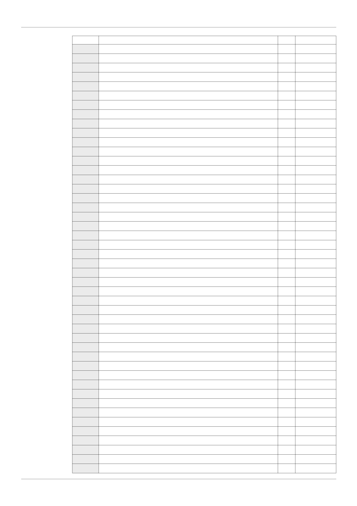
Parameters Reset Tables
Parameter
Description
Unit
Default Value
F211
[VIB freq. point 1]
Hz
0.0
F212
[VIB ref. point 2]
%
100
F240
[Mot start freq.]
Hz
0.5
F241
[Freq. pedestal]
Hz
0.0
F242
[Freq. pedestal hyst.]
Hz
0.0
F250
[DC brake start freq.]
Hz
0.0
F251
[DC braking current]
A
50
F252
[DC braking time]
s
1.0
F256
[Time limit low spd]
s
0.0
F264
[+speed LI resp time]
s
0.1
F265
[+speed freq. step]
Hz
0.1
F266
[- speed LI resp time]
s
0.1
F267
[- speed freq. step]
Hz
0.1
F268
[Init +/- Speed]
Hz
0.0
F269
[Init +/- Speed memo]
-
1
F270
[Jump frequency 1]
Hz
0.0
F271
[Jump bandwidth 1]
Hz
0.0
F272
[Jump frequency 2]
Hz
0.0
F273
[Jump bandwidth 2]
Hz
0.0
F274
[Jump frequency 3]
Hz
0.0
F275
[Jump bandwidth 3]
Hz
0.0
F294
[Forced speed freq.]
Hz
50
F295
[Switch rem/Local]
-
1
F301
[Catch on fly]
-
3
F302
[Supply loss behav.]
-
0
F305
[Overvoltage fault]
-
2
F307
[Mot volt limitation]
-
3
F311
[Motor direction]
-
1
F312
[Noise reduction]
-
0
F316
[Switch. freq. mode]
-
1
F320
[Load gain]
%
0
F323
[Load gain offset]
%
10
F359
[PID ctrl wait time]
s
0
F360
[PID control enable]
-
0
F362
[PID Prop Gain]
-
0.30
F363
[PID Integral Gain]
-
0.20
F366
[PID Derivative Gain]
-
0.00
F400
[Auto-tuning drive]
-
0
F401
[Slip Compensation]
%
50
F418
[Frequency loop gain]
-
40
F419
[Freq. loop stability]
-
20
F470
[VIA bias]
-
128
F471
[VIA gain]
-
148
F472
[VIB bias]
-
128
F473
[VIB gain]
-
148
F482
[In noise Inhibit filter]
s
442
195
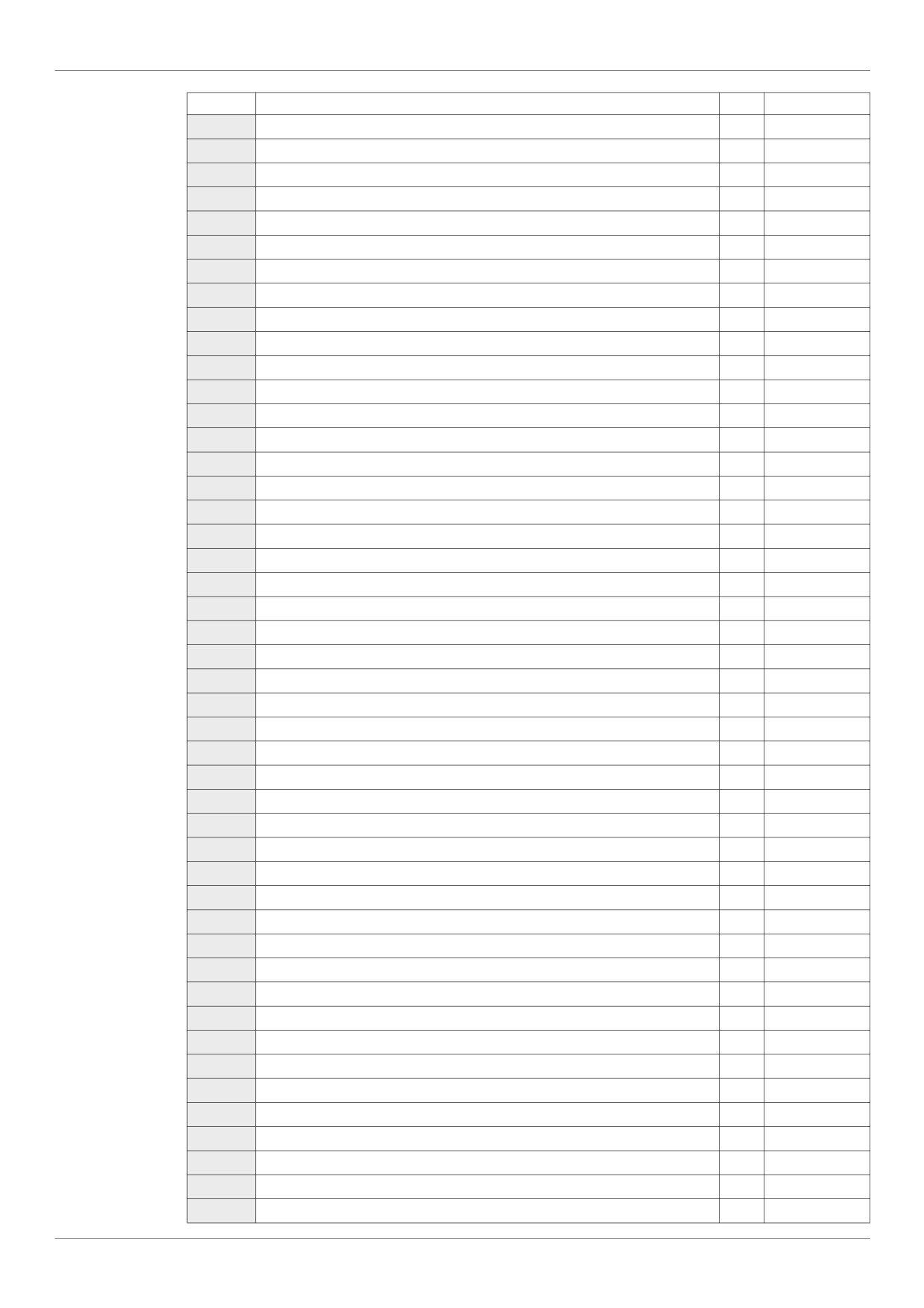
Parameters Reset Tables
Parameter
Description
Unit
Default Value
F483
[In noise inhibit gain]
-
100
F484
[Pwr supply adj. gain]
-
0.0
F485
[Stall control coef. 1]
-
100
F492
[Stall control coef. 2]
-
100
F495
[Motor voltage coef.]
%
104
F496
[PWM adj. coef.]
kHz
14.0
F502
[Acc/dec 1 pattern]
-
0
F503
[Acc/dec 2 pattern]
-
0
F504
[Ramp switching]
-
1
F505
[Commut. ramp freq.]
Hz
0.0
F506
[Acc/Dec S-pat start]
%
10
F507
[Acc/Dec S-pat end]
%
10
F602
[Drive fault memory]
-
0
F603
[Ext. fault stop Mode]
-
0
F604
[DC brk time ext flt]
s
1.0
F605
[Output phase loss]
-
3
F607
[Mot overload time]
s
300
F608
[Input phase loss]
-
1
F609
[Underload band]
%
10
F610
[Underload det.]
-
0
F611
[Underload level]
% / A
0
F612
[Underload det. time]
s
0
F613
[Short circuit det.]
-
0
F615
[Overtorque det.]
-
0
F616
[Overtorque level]
%
130
F618
[OvTorque det time]
s
0.5
F619
[Overtorque band]
%
10
F621
[Run time alarm]
h
610.0 (6100 h)
F627
[Undervolt detect.]
-
0
F632
[Mot overload memo]
-
0
F633
[Loss of VIA]
%
0
F634
[Amb. temp. alarm]
-
3
F645
[Mot PTC selection]
-
0
F646
[PTC resistor value]
3000
F650
[Forced fire control]
-
0
F691
[AO slope]
-
1
F692
[Analog output bias]
%
0
F700
[Parameter lock]
-
0
F701
[Unit value selection]
-
1
F702
[Customized freq val]
-
0
F703
[Frequency convert.]
-
0
F706
[Customize unit bias]
Hz
0.0
F707
[Loc. speed ref. step]
Hz
0.0
F708
[Display ref. resol.]
-
0
F710
[Displayed param.]
-
0
F721
[Loc. mot stop mode]
-
0
196
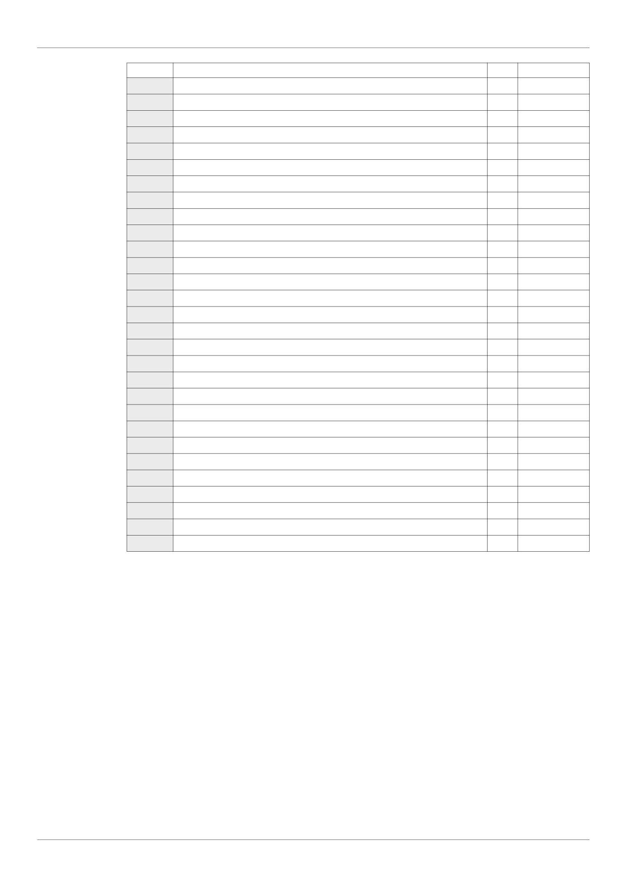
Parameters Reset Tables
Parameter
Description
Unit
Default Value
F730
[Up/down key ref]
-
0
F732
[Loc/rem key]
-
0
F733
[Run/stop key]
-
0
F734
[Priority stop]
-
0
F735
[HMI reset button]
-
1
F738
[Quick menu AUF]
-
0
F748
[Power cons. memo]
-
1
F800
[Mdb RJ45 baud]
-
1
F801
[Mdb RJ45 parity]
-
1
F802
[Modbus address]
-
1
F803
[Com. time out]
s
3
F829
[Network protocol]
-
1
F851
[Com. fault setting]
-
4
F856
[Mot. poles (comm.)]
-
2
F870
[Block write data 1]
-
0
F871
[Block write data 2]
-
0
F875
[Block read data 1]
-
0
F876
[Block read data 2]
-
0
F877
[Block read data 3]
-
0
F878
[Block read data 4]
-
0
F879
[Block read data 5]
-
0
F880
[Free ID parameter]
-
0
F890
[Network adress]
-
(1)
F891
[Network baud rate]
-
(1)
F892
[Network time out]
-
(1)
F893
[Instance number H]
-
(1)
F894
[Instance number L]
-
(1)
F895
[Max master]
-
(1)
F896
[Max info frames]
-
(1)
(1) See table page 199.
197
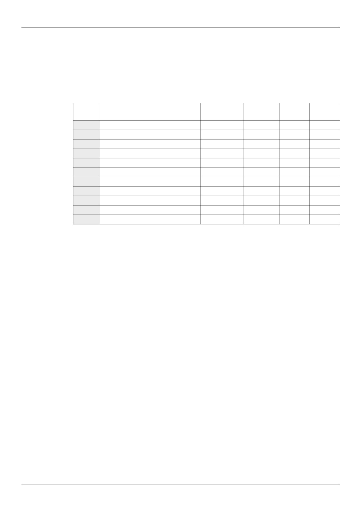
Parameters Reset Tables
Parameter values that vary according to reset type
The table below lists the parameters whose values, after a reset, depend on the reset type
([Parameter reset] (tYP) = 1, [Parameter reset] (tYP) = 2, or [Parameter reset] (tYP) = 3).
To determine the value of a parameter after a reset, locate the parameter in the first column and read across the
row to the column that corresponds to the reset type. The number that appears at the intersection of the
parameter and the reset type is the parameter’s value after a reset of the corresponding type.
Parameters whose values after a reset vary by reset type
Factory Reset
50 Hz Reset
60 Hz Reset
Parameter
Description
Unit
tYP = 3
tYP = 1
tYP = 2
CMOd
[Command mode sel]
-
0
0
0
FMOd
[Frequency mode sel]
-
1
1
1
FH
[Max frequency]
Hz
50
50
60
UL
[Upper limit freq]
Hz
50
50
60
uL
[Motor rated freq.]
Hz
50
50
60
F170
[Mot 2 rated Freq.]
Hz
50
50
60
F204
[VIA freq. point 2]
Hz
50
50
60
F213
[VIB freq. point 2]
Hz
50
50
60
F303
[Number auto reset]
-
0
0
0
F480
[No load cur. coef]
%
100
0
100
F481
[In noise comp. filter]
micro-seconds
0
100
0
198
Parameters Reset Tables
Parameter values that vary According to drive rating, but not reset type
The table below lists the parameters whose values, after a reset, depend on the drive model.
To determine the value of a parameter after a reset, locate the drive model number in first column and read
across the row to the column that corresponds to the parameter code. The number that appears at the
intersection of the model number and the parameter code is the parameter’s value after a reset. These values
are the same for every reset types ([Parameter reset] (tYP) = 1, [Parameter reset] (tYP) = 2, or
[Parameter reset] (tYP) = 3).
Parameters whose values after a reset are drive model dependant but do not vary by reset type
Parameter
Reference
ACC
dEC
vLv
ub
F171
F172
F300
F402
F494
F626
F749
s
s
V
%
V
%
kHz
%
-
%
-
ATV212H075M3X
10
10
200
6
200
6
12
5.8
80
140
0
ATV212HU15M3X
10
10
200
6
200
6
12
4.3
70
140
0
ATV212HU22M3X
10
10
200
5
200
5
12
4.1
70
140
0
ATV212HU30M3X
10
10
200
5
200
5
12
3.7
70
140
0
ATV212HU40M3X
10
10
200
5
200
5
12
3.4
70
140
1
ATV212HU55M3X
10
10
200
4
200
4
12
3.0
70
140
1
ATV212HU75M3X
10
10
200
3
200
3
12
2.5
70
140
1
ATV212HD11M3X
10
10
200
2
200
2
12
2.3
60
140
1
ATV212HD15M3X
10
10
200
2
200
2
12
2.0
50
140
1
ATV212HD18M3X
30
30
200
2
200
2
8
2.0
50
140
1
ATV212HD22M3X
30
30
200
2
200
2
8
1.8
50
140
1
ATV212HD30M3X
30
30
200
2
200
2
8
1.8
50
140
1
ATV212H075N4
10
10
400
6
400
6
12
5.8
80
140
0
ATV212HU15N4
10
10
400
6
400
6
12
4.3
70
140
0
ATV212HU22N4
10
10
400
5
400
5
12
4.1
70
140
0
ATV212HU30N4
10
10
400
5
400
5
12
3.7
70
140
0
ATV212HU40N4
10
10
400
5
400
5
12
3.4
70
140
1
ATV212HU55N4
10
10
400
4
400
4
12
2.6
70
140
1
ATV212HU75N4
10
10
400
3
400
3
12
2.3
70
140
1
ATV212HD11N4
10
10
400
2
400
2
12
2.2
60
140
1
ATV212HD15N4
10
10
400
2
400
2
12
1.9
50
140
1
ATV212HD18N4
30
30
400
2
400
2
8
1.9
50
140
1
ATV212HD22N4S
30
30
400
2
400
2
6
1.8
50
140
1
ATV212HD22N4
30
30
400
2
400
2
8
1.8
50
140
1
ATV212HD30N4
30
30
400
2
400
2
8
1.8
50
140
1
ATV212HD37N4
30
30
400
2
400
2
8
1.8
50
140
2
ATV212HD45N4
30
30
400
2
400
2
8
1.7
50
140
2
ATV212HD55N4
30
30
400
2
400
2
8
1.6
40
140
2
ATV212HD75N4
30
30
400
2
400
2
8
1.5
40
140
2
199