Altivar 212 Variable speed drives for synchronous and asynchronous motors. Programming Manual (2014) - page 3
Motor Control Parameters
Code
Name / Description
Adjustment range
Factory setting
F418
[Frequency loop gain]
1 to 150
40
Parameters F418 and [Freq. loop stability] (F419) reduce the speed of the drive’s response to a change in speed command.
The factory setting of these two parameters assumes that the inertia of the load is three times as large as that of the motor shaft.
Adjust these two parameters if the factory setting is not appropriate for the application.
Note: It is possible for the drive’s output frequency to exceed its upper limit (parameter [Max frequency] (FH)) if the acceleration
parameter (ACC or F507) is set to its minimum value.
Increasing the setting of parameter F418 reduces the drive’s response time to changes in the speed reference.
F419
[Freq. loop stability]
Frequency loop stability
1 to 100
20
Increasing the setting of parameter F419 further reduces the drive’s response to changes in the speed reference.
80
Motor Control Parameters
Permanent Magnet Motor Control Law ([PM Control] (PM))
Drive may be set to control synchronous motor. When [PM control] is activated, motor parameters are set to new
default value. You can access to additional settings to optimize the motor control.
Motor parameters setting.
These motor parameters below are needed to set:
1 - Set (Pt) [Mot cont. mode sel.] to [PM Control] (6) see page 82.
2 - Set [Motor rated freq.] (uL), see page 74:
Note: Motor rated freq.] (uL) = [Motor rated speed] (F417) / (60 / np)
[Motor rated speed] (F417), see page 74, indicated on the motor nameplate or follow the procedure step 4 above.
np = Number of pole pairs, indicated on the motor nameplate.
3 - Set the Motor rated power (unit is kW) by [Motor rated cap.] (F405), see page 82
Note: P = C x ω
P = Power in W
C = N.m, indicated on the motor nameplate.
ω = rad s-1
ω = 2π x (FRS/np)
FRS = [Motor rated freq.] (uL) see page 74, indicated on the motor nameplate.
np = Number of pole pairs, indicated on the motor nameplate.
4 - Motor rated current (unit is A) is set by [Motor rated current] (F415), see page 74.
5 - Set [Motor rated speed] (F417), see page 74, without information:
Set the motor rated speed by FRS x (60 / np)
FRS = [Motor rated freq.] (uL) see page 74, indicated on the motor nameplate.
np = Number of pole pairs, indicated on the motor nameplate.
6 - Configure [Auto-tuning drive] (F400) to [Tun Static 2] (5), see page 83. Make the TUN (Run order is needed to start the
TUN.)
- Motor’s rated voltage is set by [Motor Rated Voltage] (uLu)a, see page 82.
- Stator resistance is set by [Auto Torque Boost] (F402)a, see page 84.
- Axis "q" stator inductance in mH is set by [Autotune L q-axis] (F912)a, see page 85.
- Axis "d" stator inductance in mH is set by [Autotune L d-axis] (F913)a, see page 85.
7 - Check the value of [Saliency Level] (F936), see page 84.
8 - Set [PM mode selection] (F915) according to the [Saliency Level] (F936) value (see page 84).
9 - If (F936) is u 0.2, increase [Init. Pos. Current] (F921) see page 85 .
Configure [Auto-tuning drive] (F400) to [Tun Static 2] (5), see page 83. Make the TUN (Run order is needed to start the
TUN.)
10 - Start the motor,
- if there is current limitation on starting, increase the [PM Align cur. Level] (F916) value (See page 85).
- if its behavior is not optimal, reduce by 20% [Motor Rated Voltage] (uLu) value (see page 82).
- After this procedure, if you need further assistance, contact your Schneider Electric Product Support.
(a) Auto Torque Boost] (F402) , [Autotune L q-axis] (F912), [Autotune L d-axis] (F913), and [Motor Rated Voltage]
(uLu) may be defined automatically after activation of [Auto-tuning drive] (F400) = [Tun Dyn. 2] (3) or [Tun Static 2] (5)
81
Motor Control Parameters
Code
Name / Description
Adjustment range
Factory setting
Pt
[Mot cont. mode sel.] Motor control mode selection
-
1
If [Driving Scroll] (F324) page 160 is set to [yes] (1) the setting is replaced by [SVC] (3)
0
[Constant V/Hz]: Constant V/Hz
1
[Variable Torque]: Variable torque
2
[Cst V/Hz+Boost]: Constant V/Hz with automatic torque boost
3
[SVC]: Sensorless vector control
4
[Economy]: Energy saving
5
[Do not use]: Reserved
6
[PM Control]: Permanent Magnet Motor Control Law
DANGER
HAZARD OF ELECTRIC SHOCK, EXPLOSION OR ARC FLASH
If [Mot cont. mode sel.] (Pt) is set to (6) (Permanent Magnet Motor Control Law), output phase loss monitoring, while the motor
is running, is disabled. Phase loss and, by implication, accidental disconnection of cables, are not detected.
Verify that this behavior does not result in unsafe conditions and implement alternative monitoring function if required.
Failure to follow these instructions will result in death or serious injury.
uLu
[Motor Rated Voltage]
According to drive
According to
rating (1)
drive rating (1)
Set parameter uLu (vLv) to the motor’s rated voltage as indicated on the motor nameplate.
ATV212pppM3X: 50...330 V
ATV212pppN4: 50...660 V
Note: Drive output voltage cannot be set to exceed the input line voltage level.
uLu (vLv) may be defined automatically after activation of F400 = [Tun Dyn. 2] (3) or [Tun Static. 2] (5) if [Mot cont. mode
sel.] (Pt) = (6)
uL
[Motor rated freq.]
25.0 to 400 Hz
50.0 Hz
Set parameter uL(vL) to the motor’s rated frequency as indicated on the motor nameplate.
Note: It is possible to set the drive’s various motor control frequencies to 50 Hz by setting [Parameter reset] (tYP) to 1, the
50 Hz reset. For more information, see page 66.
F405
[Motor rated cap.]
Motor rated capacity
0.01 to 75 kW
According to
drive rating (1)
Set parameter F405 to the motor rated capacity in kilowatt.
It permite to calculate automatically [Motor Rated Voltage] (uLu) after TUN F400 [Auto-tuning drive]
F415
[Motor rated current]
0.1 to 200.0 A
According to
drive rating (1)
Set parameter F415 to the motor rated current in amperes as indicated on the motor’s nameplate.
F417
[Motor rated speed]
Motor rated speed
100.0 to 15000 rpm
According to
drive rating (1)
Set parameter F417 to the motor rated speed in rpm as indicated on the motor’s nameplate.
(1) See table page 199.
82
Motor Control Parameters
F400
[Auto-tuning drive]
-
0
DANGER
HAZARD OF ELECTRIC SHOCK OR ARC FLASH
During auto-tuning, the motor operates at rated current.
Do not service the motor during auto-tuning.
Failure to follow these instructions will result in death or serious injury.
WARNING
LOSS OF CONTROL
It is essential that the following parameters uLu, uL, F415 and F417 are correctly configured before starting auto-
tuning.
When one or more of these parameters have been changed after auto-tuning has been performed, F400 will return 0
and the procedure will have to be repeated.
Failure to follow these instructions can result in death or serious injury.
NOTICE
RISK OF DAMAGE TO THE MOTOR
Conduct auto-tuning only after the motor has been connected and operation completely stopped.
If auto-tuning is conducted immediately after operation stops, the presence of a residual voltage may result in abnormal
tuning.
Failure to follow these instructions can result in equipment damage.
Auto tuning enable
0
[Disabled]
1
[Initialize constant]:
Factory setting of [Auto Torque Boost] (F402) for asynchronous motor.
Factory setting of [Auto Torque Boost] (F402) , [Autotune L q-axis] (F912), and [Autotune L d-axis] (F913), and
[Motor Rated Voltage] (vlv) for synchronous motor.
2
[Tun Dyn. 1]:Tune Dynamic, with driving run after the tuning.
Application settings of [Auto Torque Boost] (F402) for asynchronous motor.
Application settings of [Auto Torque Boost] (F402) , [Autotune L q-axis] (F912), and [Autotune L d-axis] (F913) for
synchronous motor.
3
[Tun Dyn. 2]: Complete tune Dynamic, with driving run after the tuning.
Application settings of [Auto Torque Boost] (F402) , [Autotune L q-axis] (F912), [Autotune L d-axis] (F913), and
[Motor Rated Voltage] (vlv) for synchronous motor.
4
[Tun Static 1]: Tune Static, without driving run after the tuning.
Application settings of [Auto Torque Boost] (F402) for asynchronous motor.
Application settings of [Auto Torque Boost] (F402) , [Autotune L q-axis] (F912), and [Autotune L d-axis] (F913) for
synchronous motor.
5
[Tun Static 2]: Complete tune Static, without driving run after the tuning.
Application settings of [Auto Torque Boost] (F402) , [Autotune L q-axis] (F912), and [Autotune L d-axis] (F913), and
[Motor Rated Voltage] (vlv) for synchronous motor.
Parameter F400 is reset to “0” after the auto tuning is performed.
F458
[Current loop gain]
Current loop gain
0...100 Hz
0 Hz
Parameter F458 is set to the response gain of current loop.
If [Mot cont. mode sel.] (Pt) page 82 is set to [PM control] (6) the setting is replaced by 25 Hz.
Note: Contact Schneider electric product support to confirm the modification of this parameter.
(1) See table page 199.
83
Motor Control Parameters
F418
[Frequency loop gain]
1 to 150
40
Parameters F418 and [Freq. loop stability] (F419) reduce the speed of the drive’s response to a change in speed command.
The factory setting of these two parameters assumes that the inertia of the load is three times as large as that of the motor shaft.
Adjust these two parameters if the factory setting is not appropriate for the application.
Note: It is possible for the drive’s output frequency to exceed its upper limit (parameter [Max frequency] (FH)) if the acceleration
parameter (ACC or F507) is set to its minimum value.
Increasing the setting of parameter F418 reduces the drive’s response time to changes in the speed reference.
F419
[Freq. loop stability]
Frequency loop stability
1 to 100
20
Increasing the setting of parameter F419 further reduces the drive’s response to changes in the speed reference.
F495
[Motor voltage coef.] Maximum voltage adjustment coefficient
90 to 120%
104%
Use parameter F495 to limit the drive’s maximum output voltage. Increasing this setting increases torque when the motor is
operated above its rated frequency, but may also cause motor vibration. Do not increase the value of F495 if motor vibrations
occur.
F936
[Saliency Level]
Saliency coefficient for PM motor
0 to 2.55
0
PM type [PM mode selection] (F915) is selected by the saliency level [Saliency Level] (F936)
F936 u 0.2 = high saliency
F936 < 0.2 = low saliency.
Note: This parameter is automatically computed with the setting of [Autotune L q-axis] (F912) and [Autotune L d-axis] (F913)
F915
[PM mode selection] PM control mode selection
-
3
0
[Basic Ctrl]: basic control
1
[Ctrl Type1]: control type 1 (for IPM, interior-buried Permanent Magnet motor)
2
[Ctrl Type2]: control type 2 (for IPM, interior-buried Permanent Magnet motor)
3
[Ctrl Type3]: control type 3 (for IPM / SPM, interior-buried Permanent Magnet motor / Surface-mounted Permanent Magnet motor)
4
[Ctrl Type4]: control type 4 (for IPM / SPM, interior-buried Permanent Magnet motor / Surface-mounted Permanent Magnet motor)
Refer to the following tables to select the setting of the parameter F915, F915 is selected by the saliency level F936
- big starting torque is needed.
- big starting torque is not needed.
- big starting torque is not needed
- for constant torque application.(1)
- for variable torque application (2)
- for variable torque application
- motor electrical magnetic noise is
forbidden (3)
The saliency level is
F915 = 4 or 2
F915 =1 or 3
F915 =0
high (F936 u 0.2)
The saliency level is
F915 =3
low (F936 < 0.2)
(1) There is some motor electrical magnetic noise at start and low speed area.
(2) There is some motor electrical magnetic noise at start. It can not be started in case of high start-up torque.
(3) It goes opposite direction at start sometimes. It cannot be started in case rotor saliency is high.
Code
Name / Description
Adjustment range
Factory setting
F402
[Auto Torque Boost]
0.0 to 30.0%
According to drive
rating
Use parameter F402 to adjust the amount of automatic torque boost that is applied.
Motor rated voltage
: Automatically
adjusts the
amount of
0
torque boost.
Motor Rated Frequency
Output Frequency (Hz)
84
Motor Control Parameters
F912
[Autotune L q-axis] q-axis self-inductance
0.01 to 650 mH
10
Axis "q" stator inductance in mH
The setting is replaced by the result of the auto-tuning operation, if it has been performed.
Measured between the neutral and the phase, its value could be differente than the datasheet of the motor.
[Autotune L q-axis] (F912) is defined automatically after activation of [Auto-tuning drive] (F400) = [Tun Dyn. 2] (3)
F913
[Autotune L d-axis] d-axis self-inductance
0.01 to 650 mH
10
Axis "d" stator inductance in mH
The setting is replaced by the result of the auto-tuning operation, if it has been performed.
Measured between the neutral and the phase, its value could be differente than the datasheet of the motor.
[Autotune L q-axis] (F913) is defined automatically after activation of [Auto-tuning drive] (F400) = [Tun Dyn. 2] (3)
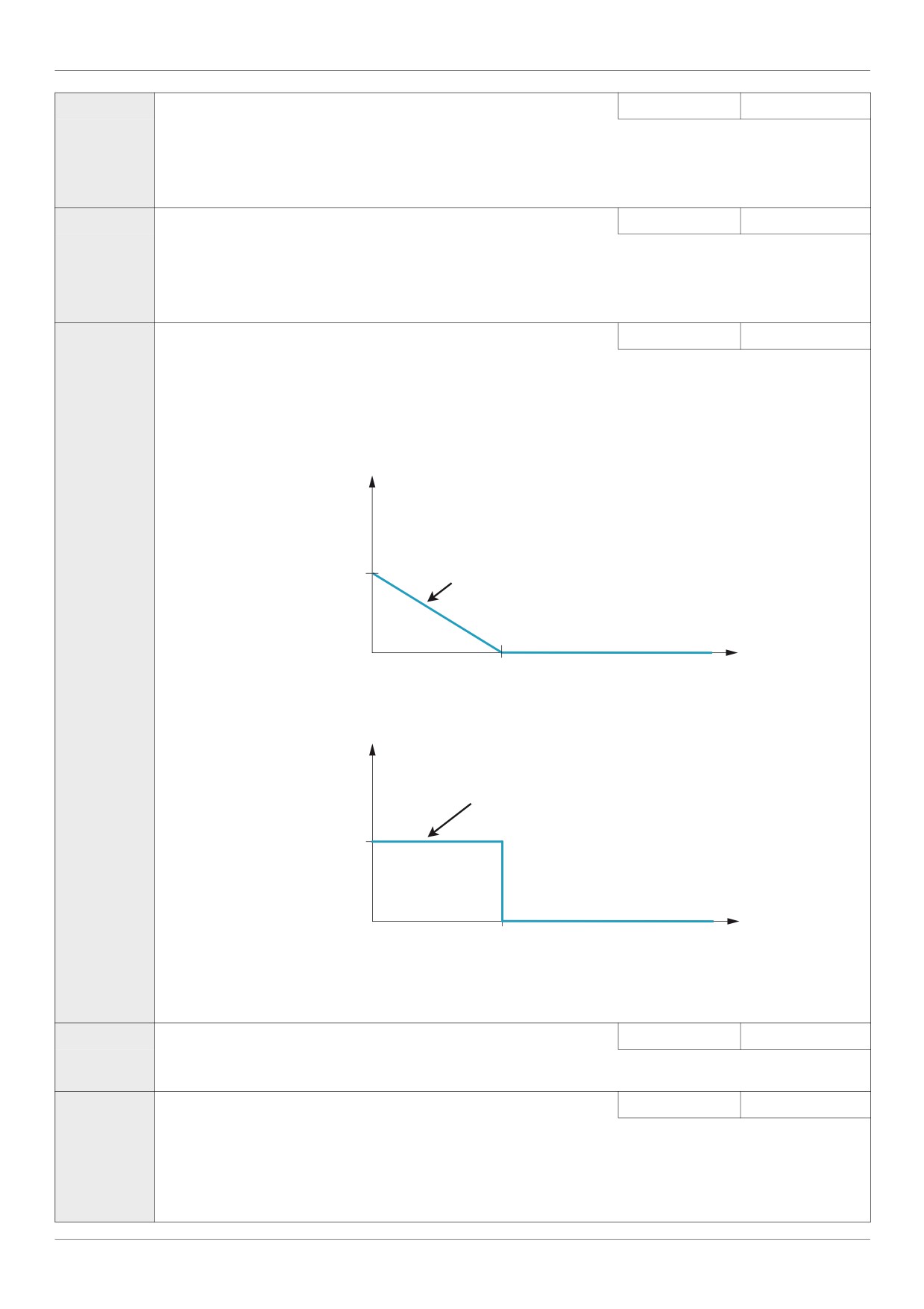
F916
[PM Align cur. Level] Stabilization at the starting and low speed(for PM)
0 to 100 %
25 %
It might be able to stabilize the motor rotation behavior by the current in D axis at no load when starting or low-speed
If you have a torque jolt, when starting / stopping or low-speed, it is recommended to increased the setting of 916.
If E-20 [Excess torque boost flt] trip occurs at the start, it is recommended to increased the setting of 916.
In the case of F915=0, 1, 2, 3
Current Level (%)
Stabilization current in D axis
F916 to 25 %
0
K*Fn (K*vL)
Rotor speed
In the case of F915=4
Current Level (%)
Stabilization current in D axis
F916 to 25 %
0
K*Fn (K*vL)
Rotor speed
Starting current F916 is set 25% as the default setting,
Limit it to the value of about 75% in the maximum with consideration of copper loss and iron loss of the motor.
If the loss of motor at no load is made decreased, please decrease the value of F916 confirming the stability when starting.
F921
[Init. Pos. Current]
Current for initial position estimation
10 to 150 %
100 %
In case of position detection 3, the current level can be set by this parameter, during the auto-tuning for d axis / q axis inductance,
the maximum current level can be adjusted by this parameter setting.
F420
[Torque Boost Coef] Compensation coefficient of torque boost
0 to 200%
90 %
If synchronous or asynchronous motor is used, F420 [Torque Boost Coef] is set to 90%.
If you have a torque jolt, when starting / stopping or low-speed, increase the value of F420
Note:
If E-20 [Excess torque boost flt] trip occurs at the start, it is recommended to be decreased the setting of F420
85

Motor Control Parameters
Parameters described in this page can be accessed by the extended menu
Code
Name / Description
Adjustment range
Factory setting
F914
[N-S direction]
Method of detection
0 - 1
0
N-S Method of detection.
0
If F914 = 0, the N-S direction of rotor position is judged by the method of DC offset for position detection.
1
If F914 = 1, the N-S direction of rotor position is judged by the method of AC offset for position detection.
Note : N-S method of detection is available if [PM mode selection] (F915) is set to [Ctrl Type1] (1) or [Ctrl Type2] (2)
F917
[PM Max torq. Ctrl]
Max torque control activation (for IPM)
0 - 1
1
0
[0] : Deactivation
1
[1] : Activation
F918
[Cur. phase adjt]
- 45.0 to 45.0
0
It is possible to aim the higher efficiency in the case of IPM (Interior Permanent Magnet), by activation of [PM Max torq. Ctrl] (F917)
which makes required current the minimum, the loss of m otor and driver may be reduced and the efficiency may be attained higher
level.
F920
[Position Adjust]
0 - 150 %
0 = Auto
In case of heavy load, the estimated position can be adjusted by setting this parameter.
Adjustment for position estimation, available if [PM mode selection] (F915) is set to [Ctrl Type2] (2) or |Ctrl Type4] (4).
86

Drive Control Parameters
Drive Control Parameters
6
Code
Name / Description
Adjustment range
Factory setting
CMOd
[Command mode sel]
Remote Mode Start/Stop Control
-
0
The setting of parameter CMOd determines the source of start, stop, forward, and reverse operation commands when the drive is
in remote mode.
The drive needs to be stopped to make changes to parameter CMOd.
See diagram on page 50 and description page 54 for more information on the source of the drive’s operation commands.
0
[Logic inputs]: Control terminal logic inputs
1
[HMI]: Graphic display option
2
[Communication]: Serial communication
FMOd
[Frequency mode sel]
Remote Mode Primary Speed Reference Source
-
1
The setting of parameter FMOd determines the source of the drive’s speed reference when the drive is in remote mode.
The drive needs to be stopped to make changes to parameter FMOd.
See diagram on page 50 and description page 54 for more information on the source of the drive’s speed reference.
1
[Ref source VIA]: VIA
2
[Ref source VIB]: VIB
3
[HMI reference]: Graphic display option
4
[Serial com ref.]: Serial communication
5
[+/- Speed]: +/- Speed
FC
[Local speed ref.]
Local Mode Speed Reference
LL - UL
0.0 Hz
The speed reference set by the UP/DOWN keys in local mode will be stored in parameter FC when the ENT key is pressed.
The next time the drive is Power ON in local mode, it will accelerate the motor directly to the speed setpoint memorized by FC.
Fr
[Local mot. direction]
Local Mode Motor Rotation Direction Command
-
0
0
[Run FW]: Run forward only.
1
[Run rev.]: Run reverse only.
2
[Run FW+rev]: Run forward with reverse selectable.
3
[Run rev+FW]: Run reverse with forward selectable.
If Fr is set to 2 or 3:
The motor direction can be changed in local mode to forward by pressing the UP key while holding the ENT key and to reverse by
pressing the DOWN key while holding the ENT key.
The new motor direction will be displayed (forward = Fr-F, reverse = Fr-r) before the motor direction is reversed.
The motor’s last operating direction in local mode will be stored before a power removal or loss detection. When power is restored
to the drive, the local mode motor rotation direction will be the same as before the power loss detection.
If [Switch rem/Local] F295 (see page 88) is enabled and control is transferred from remote to local mode, the local mode operation
will assume the same motor rotation direction as in remote mode, regardless of the setting of Fr.
F707
[Loc. speed ref. step]
Local Mode Speed Reference Step Changes
-
0.0 Hz
0
[Disable]: Disabled (0.00).
1
[Enable]: Enabled (0.01 to Maximum Frequency [Max frequency] (FH) in Hz).
If parameter F707 is disabled in local mode, the drive’s speed reference will change in steps of 0.1 Hz each time the UP or DOWN
key is pressed.
If parameter F707 is enabled in local mode, the drive’s speed reference will change in steps equal to the setting of F707 each
time the UP or DOWN key is pressed.
Enabling parameter F707 only affects drive operation if parameter [Customized freq val] (F702) is set to 0.00. See page 131.
If the display flashes “HI” or “LO”, it indicates that repeated usage of the UP or DOWN keys has caused to drive’s speed reference
to reach either the [Low limit frequency] (LL) (see page 92) or the [Upper limit freq] (UL) (see page 92). This may happen if param-
eter F707 is set to a value larger than 0.00 Hz.
87
Drive Control Parameters
Code
Name / Description
Adjustment range
Factory setting
F721
[Loc. mot stop mode]
Local Mode Motor Stop Type
-
0
The setting of parameter F721 determines the type of motor stop that will be executed when then embedded display terminal
STOP key is pressed.
The RUN and STOP keys needs to be enabled be setting parameter [Run/stop key] (F733) (see page 90) to 0 for the motor to
stop when the embedded display terminal STOP key is pressed.
0
[Ramp stop]: Ramp stop
1
[Freewheel]: Freewheel stop
F295
[Switch rem/Local]
Bumpless transfer from remote to local control
-
1
If parameter F295 is enabled, the speed reference, run and direction commands will be transferred from remote to local mode
when the LOC/REM key is pressed. Operation of the drive is not affected by a remote to local control mode transition.
If parameter F295 is disabled, a remote to local control mode transition will cause the drive to remove power from the motor. A
new run command and speed reference will need to be entered in the local mode.
Regardless of the setting of parameter F295, a local to remote transition will cause the drive to immediately respond to the remote
commands present at the moment of the transition.
0
[No bumpless]: Bumpless disabled
1
[Bumpless]: Bumpless enabled
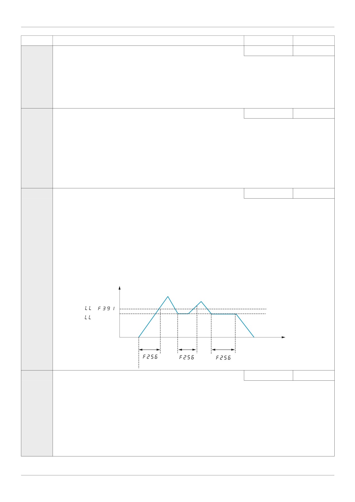
F256
[Time limit low spd]
0.0 to 600 s
0.0 s
0
[Disable]: (0.0)
1
[Enable]: (0.01 to 600 seconds)
If parameter F256 is enabled and if the drive operates continuously at [Low limit frequency] (LL) (see page 92) for a time period
equal to the setting of F256, the drive will ramp the motor to a stop. While the motor is stopped, “LStP” will flash on the drive
embedded display terminal.
When the speed reference to the drive exceeds the low speed level LL+F391, the drive will accelerate the motor to the new speed
reference.
If parameter F256 is enabled, drive operation at or below the low speed level is also monitored during startup or during reversing
of the motor. See diagram below.
Output
frequency (Hz)
+
Time (s)
ON
OFF
Run
Command
F207
[Remote spd ref 2]
-
2
1
VIA
2
VIB
3
HMI
4
Communication
5
+/- Speed
Parameter [Remote spd ref 2] (F207) defines the remote mode secondary speed reference source. The setting of parameter [Au-
to/man speed ref] (F200) (see page 118) determines whether this source is used for the speed reference.
If F200 is set to 0, a logic input terminal set to function 38 (see page 118) determines if [Remote spd ref 2] (F207) identifies the
speed reference source.
If F200 is set to 1, [Remote spd ref 2] (F207) is the speed reference source when the drive’s output frequency is 1 Hz or below.
See diagram on page 50 for more detail.
88
Drive Control Parameters
Code
Name / Description
Adjustment range
Factory setting
F650
[Forced fire control]
-
0
WARNING
LOSS OF CONTROL
The value of F650 will impact the direction of the motor.
- Check wiring motor power UVW is correct.
- Verify that the value of F650 is convenient for this application.
Failure to follow these instructions can result in death, serious injury, or equipment damage.
0
[Disable]
1
[Enable forward]
2
[Enable Reverse]
To enable Forced fire control, set parameter F650 to1 or 2 and assign a logic input to function 52 or 53 (see page 104). When
parameter F650 is set to1 or 2, the embedded display will briefly flash the code FIrE.
If parameter F650 is set to1 or 2 and a logic input assigned to function 52 or 53 is activated, the drive will run at the frequency
set by parameter [Forced speed freq.] (F294) (see below).
Note:
• First set [Motor direction] (F311) page 96 to allow forward or reverse operation.
• Push the ENT button for 2 sec to complete the setting.
• See F659 for more information of the behavior.
F659
[Forced fire function]
-
0
0
[Enable transition]
When parameter F659 is set to 0, the function is enabling on transition 0 -->1 of the logic input. The transition 1 -->0 will not disable
the function.
WARNING
LOSS OF CONTROL
If the Forced fire mode on logic input (function 52) has been enabled and F659 is set to 0, the drive will run and only removing
power from the drive will stop it.
If the Fire mode on logic input (function 53) has been enabled and F659 is set to 0, the drive will run and only removing power
from the drive or a fault detection or a pressing on the STOP key on the display terminal will stop the drive.
Check that this value of F659 is convenient for the application.
Failure to follow these instructions can result in death, serious injury, or equipment damage.
1
[Enable level 1]
When parameter F659 is set to 1, if the logic input is set to 0 the function is disabled.
If the logic input is set to 1 the function is enable
WARNING
RISK OF APPLICATION MALFUNCTION
When F659 is set to 1 for safety reason, the forced mode will be inhibited if the logic input is inactivated for any reason (order
removed, input broken, wiring contact lost).
- Check that this value of F659 is conveniant for the application.
- If you need to continue to run if forced mode in any circonstance, select an other value of F659.
Failure to follow these instructions can result in death, serious injury, or equipment damage.
2
[Enable level 0]
When parameter F659 is set to 2, if the logic input is set to 1 the function is disabled.
If the logic input is set to 0 the function is enable.
DANGER
UNINTENDED EQUIPMENT OPERATION
When F659 is set to 2 for safety reason, the motor will run at Forced speed F294 in case of intempestive wire disconnection.
- Check and control the wiring connection periodically.
- Protect the signal conductors against damage that could result in unintentional conductor grounding.
Failure to follow these instructions will result in death or serious injury.
F294
[Forced speed freq.]
LL - UL
50.0 Hz
The F294 parameter is used to set the fixed frequency command for the drive when it is in Forced or Fire mode.
89
Drive Control Parameters
Code
Name / Description
Adjustment range
Factory setting
F730
[Up/down key ref]
0
The setting of parameter F730 determines whether it is possible to set the drive’s speed by means of the embedded display ter-
minal in local mode.
0
[Enable]
1
[Disable]
F732
[Loc/rem key]
0
Use parameter F732 to enable or disable the LOC/REM key on the drive embedded display terminal.
If the LOC/REM key is disabled, switching between local and remote mode can be achieved with parameters [Frequency mode sel]
(FMOd) and [Command mode sel] (CMOd). See page 87.
0
[Permitted memo]: still retained with the power off.
1
[Prohibited]
2
[Permitted no memo]: cancelled with the power off.
F733
[Run/stop key]
0
0
[Enable]
1
[Disable]
The setting of parameter F733 determines whether it is possible to start and stop the drive by the Run/Stop keys located
on the drive and graphic display option.
F734
[Priority stop]
0
WARNING
LOSS OF CONTROL
You are going to disable the stop button located on the drive and graphic display option
Do not select 1 unless exterior stopping methods exist.
Failure to follow these instructions can result in death, serious injury, or equipment damage.
The setting of parameter F734 determines whether it is possible to stop the drive by the Stop key located on the drive and graphic
display option.
0
[Enable]
1
[Disable]
F735
[HMI reset button]
1
The setting of parameter [HMI reset button] (F735) determines whether it is possible to clear a drive detected fault by means of
the embedded display terminal STOP key (see page 55 for more detail).
0
[Enable]
1
[Disable]
90
Application Parameters
Application Parameters
7
What's in this Chapter?
This chapter contains the following topics:
Topic
Page
Skip Frequencies
97
DC Injection Braking Parameters
98
91
Application Parameters
Application parameters
Code
Name / Description
Adjustment range
Factory setting
FH
[Max frequency]
Maximum Frequency
30.0 Hz to 400.0 Hz
50.0 Hz
If [Driving Scroll] (F324) page 160 is set to [yes] (1) the setting is replaced by 90%.
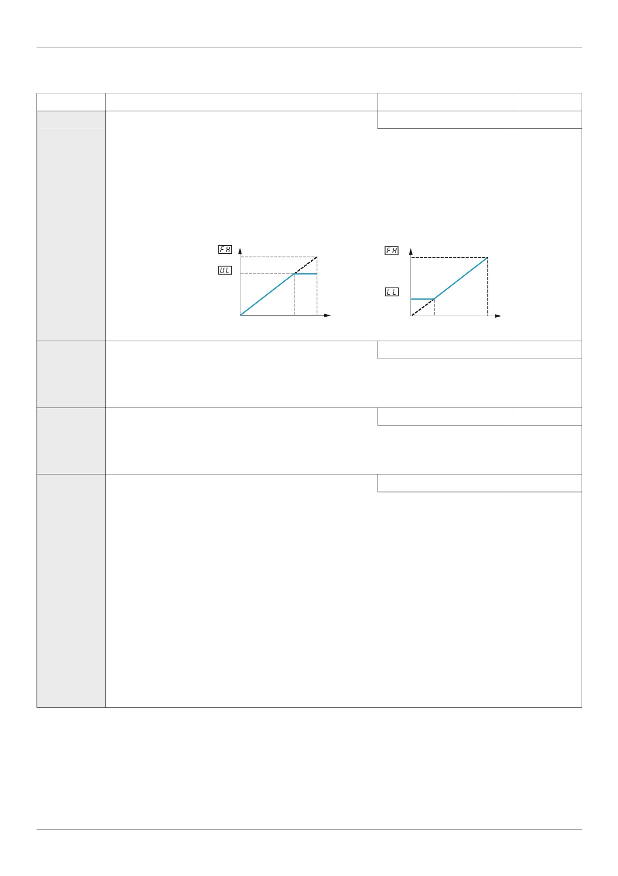
The setting of parameter FH determines the maximum output frequency of the drive.
FH limits the setting of parameter [Upper limit freq] (UL) (see page 92), which can be adjusted while the drive is operating.
Acceleration and deceleration rates are also affected by the setting of FH, as the definition of [Acceleration time 1] (ACC) or
[Deceleration time 1] (dEC) (see page 93) is the time it takes for the drive to ramp the motor up or down between zero speed
and the setting of FH.
FH can only be adjusted while the drive is stopped.
Output frequency (Hz)
Output frequency (Hz)
0
0
Speed Reference
100%
Speed Reference
100%
UL
[Upper limit freq]
High speed
0.5 to [Max frequency] (FH)
50.0 Hz
If [Driving Scroll] (F324) page 160 is set to [yes] (1) the setting is replaced by 90%.
Parameter UL sets the maximum frequency that can be commanded to the drive by the local or remote speed reference source.
The top end of its range is limited by the setting of Maximum frequency [Max frequency] (FH). See diagram above.
LL
[Low limit frequency] Low speed
0.0 to [Upper limit freq] (UL)
0.0 Hz
If [Driving Scroll] (F324) page 160 is set to [yes] (1) the setting is replaced by 30%.
Parameter LL sets the minimum frequency that can be commanded to the drive by the local or remote speed reference source.
See diagram above.
F240
[Mot start freq.]
Output Starting Frequency
0.5 to 10.0 Hz
0.5 Hz
The setting of parameter F240 determines the drive’s output frequency at the moment it receives a start command. There is
no acceleration time to reach the parameter F240 level.
Parameter F240 is typically set for the rated slip frequency of the motor. This allows motor torque to be generated as soon as
a start command is given. Adjust parameter F240 when a delay in the motor’s response to a start command adversely affects
the application.
To determine the motor’s slip frequency:
1) Subtract the motor’s rated speed at full load from it’s no-load speed (in rpm).
2) Divide the result by the no-load speed.
3) Multiply this result by the motor’s rated frequency in Hz.
Example:
Motor no-load speed = 1500 rpm
Motor rated speed at full load = 1450 rpm
Motor rated frequency = 50 Hz
1500 rpm - 1450 rpm = 50 rpm
50 rpm / 1500 rpm = 3.33%
50 Hz x 0.0333 = 1.7 Hz (motor slip frequency)
92
Application Parameters
Code
Name / Description
Adjustment range
Factory setting
ACC
[Acceleration time 1]
0.0 to 3200 s
According to
drive rating (5)
If [Driving Scroll] (F324) page 160 is set to [yes] (1) the setting is replaced by 0.9 s.
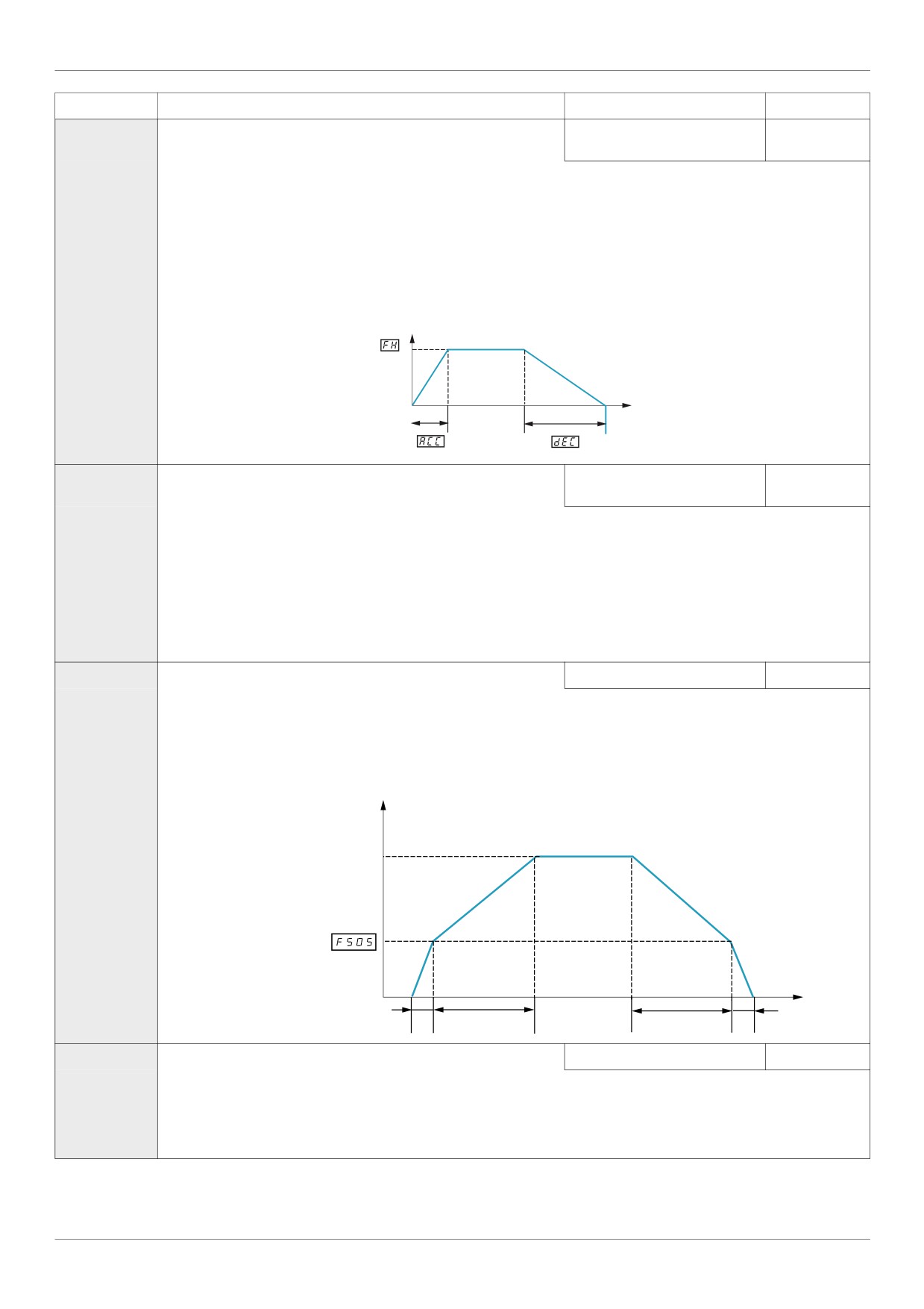
The setting of parameter ACC determines the slope of the acceleration ramp and the time it takes for the output frequency of
the drive to increase from 0 Hz to the setting of [Max frequency] (FH) (see page 92).
If parameter [Auto ramp] (AU1) (see page 95) is set to 1 or 2, the acceleration ramp may be increased or decreased from the
setting of ACC, depending on the amount of load on the motor during ramp up.
If two different acceleration rates are needed, see parameter [Acceleration time 2] (F500) on page 93.
Output frequency (Hz)
0
Time (Sec)
dEC
[Deceleration time 1]
0.0 to 3200 s
According to
drive rating (5)
If [Driving Scroll] (F324) page 160 is set to [yes] (1) the setting is replaced by 0.9 s.
The setting of parameter dEC determines the slope of the deceleration ramp and the time it takes for the output frequency of
the drive to decrease from the setting of [Max frequency] (FH) to 0 Hz.
If parameter [Auto ramp] (AU1) is set to 1, the deceleration ramp may be increased or decreased from the setting of dEC,
depending on the amount of load on the motor during ramp down. See diagram above.
If two different deceleration rates are needed, see parameter [Deceleration time 2] (F501) on page 93.
F500
[Acceleration time 2]
0.0 to 3200 s
20.0 s
Parameter F500 sets the second acceleration time. Switching between acceleration rates 1 and 2 is accomplished by means
of:
Parameter [Ramp switching] (F504) (see page 95),
A particular operating frequency (see parameter [Commut. ramp freq.] (F505) on page 95), or
A logic input assigned to functions 5, 20, 21, 30, 31 - 35, or 40 (see table beginning on page 101)
Output Frequency (Hz)
Speed Reference
(1) ACC Acceleration Slope
(2) F500 Acceleration Slope
(3) F501 Deceleration Slope
(4) dEC Deceleration Slope
Time (S)
Acceleration/Deceleration Switching
0
Logic Input
(1)
(2)
(3)
(4)
F501
[Deceleration time 2]
0.0 to 3200 s
20.0 s
Parameter F501 sets the second deceleration time. Switching between deceleration rates 1 and 2 is accomplished by means
of:
- Parameter [Ramp switching] (F504) (see page 95),
- A particular operating frequency (see parameter [Commut. ramp freq.] (F505) on page 95), or
- A logic input assigned to functions 5, 20, 21, 30, 31 - 35, or 40 (see table beginning on page 101).
(5) See table page 199.
93
Application Parameters
Code
Name / Description
Adjustment range
Factory setting
F502
[Acc/dec 1 pattern]
0
0
[Linear]
1
[S-ramp 1] (see diagram below)
2
[S-ramp 2] (see diagram below for [Acc/dec 2 pattern] (F503) parameter).
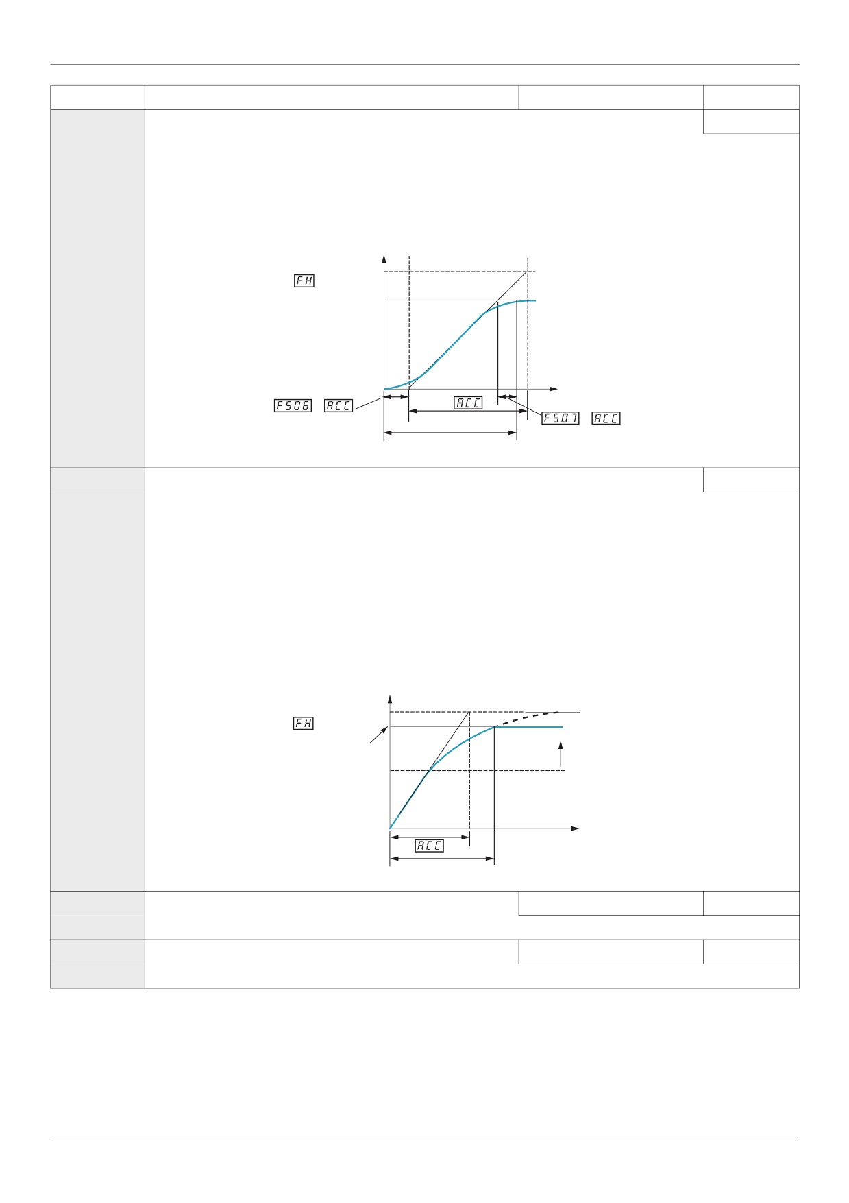
The linear acceleration and deceleration pattern is illustrated in diagram on page 93 and is used in most applications.
S-pattern 1 (see diagram below) is for use in applications that need the shortest ramp time possible while minimizing jerks during
speed changes. See below for more information about parameters [Acc/Dec S-pat start] (F506) and [Acc/Dec S-pat end]
(F507).
Output Frequency (Hz)
Maximum Frequency
Set Frequency
0
Time (S)
x
x
Actual Acceleration Time
F503
[Acc/dec 2 pattern]
0
0
[Linear]
1
[S-ramp 1] See diagram below.
2
[S-ramp 2] See previous diagram for parameter Acc/Dec Pattern 1 [Acc/dec 1 pattern] (F502).
S-pattern 2 (diagram below) is for use in high-speed spindle applications where acceleration and deceleration rates need to be
reduced as the motor operates above its rated operating frequency—a constant hp region where motor torque is reduced.
Use parameter F503 to select the second Acc/Dec pattern. Switching between Acc/Dec patterns 1 and 2 is accomplished by
means of:
Parameter [Ramp switching] (F504) (see page 95),
A particular operating frequency (see parameter [Commut. ramp freq.] (F505) on page 95), or
A logic input assigned to functions 5, 20, 21, 30, 31 - 35, or 40 (see table beginning on page 101).
For more information on Acc/Dec patterns, see parameter [Acc/dec 1 pattern] (F502) above.
Output Frequency (Hz)
Maximum Frequency
Set Frequency
Constant hp
Region
Motor Rated
Frequency
0
Time (S)
Actual Acceleration Time
F506
[Acc/Dec S-pat start] Acc/Dec S-pattern lower limit
0 to 50% of acceleration time
10%
Use parameter F506 to adjust the lower portion of S-pattern 1. See diagram on page 95.
F507
[Acc/Dec S-pat end] Acc/Dec S-pattern Upper Limit
0 to 50% of acceleration time
10%
Use parameter F507 to adjust the upper portion of the S-pattern 1. See diagram on page 95.
94
Application Parameters
Code
Name / Description
Adjustment range
Factory setting
F504
[Ramp switching]
Acc/Dec Pattern Selection
-
1
1
[Ramp 1]
2
[Ramp 2]
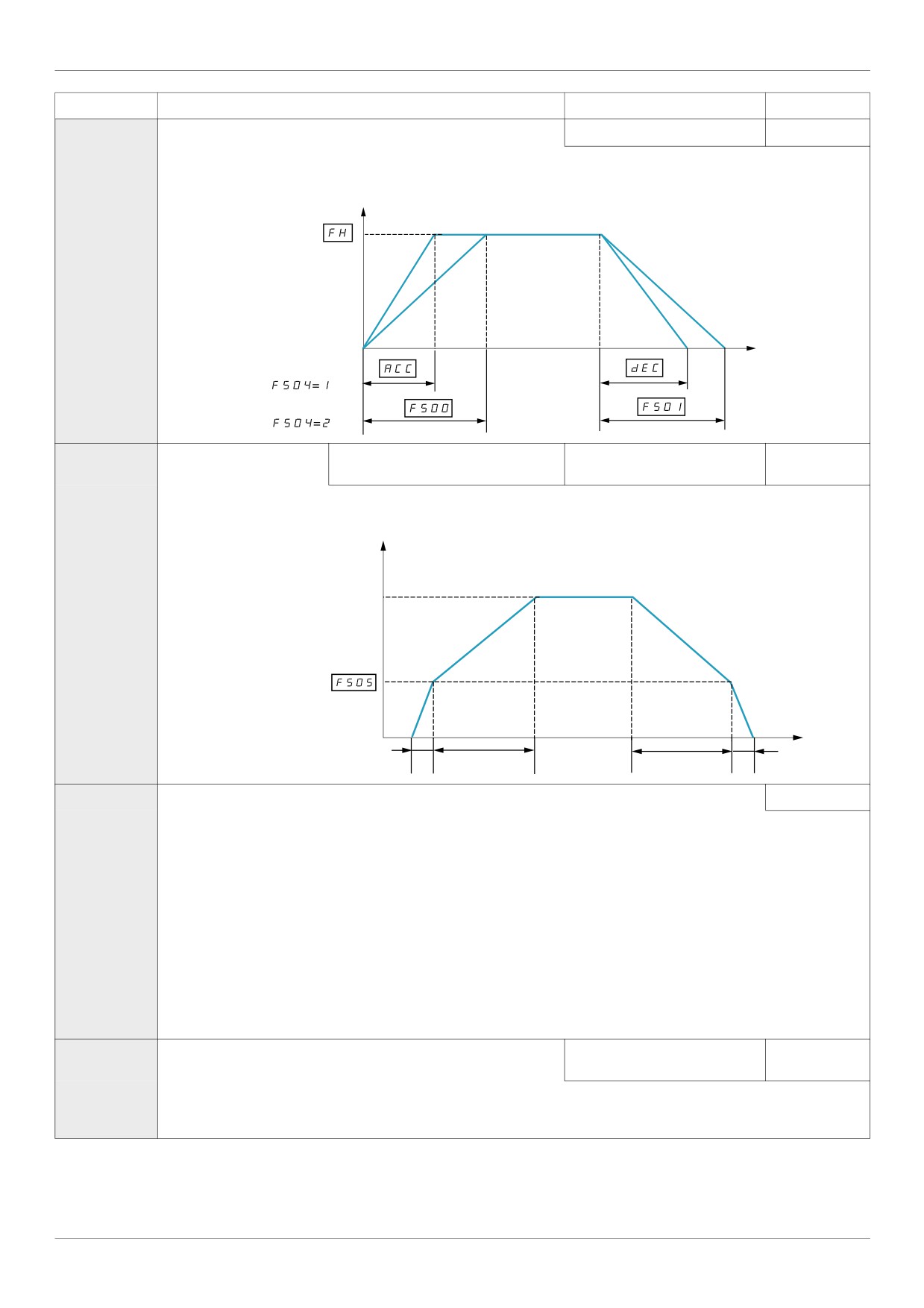
Parameter F504 determines the Acc/Dec pattern.
Output Frequency (Hz)
Time (S)
0
F505
[Commut. ramp freq.]
Acc/Dec pattern switching frequency
0.0 to [Upper limit freq] (UL)
0.0 Hz
(Hz)
If parameter F505 is set to a frequency greater than 0.0, the drive will use Acc/Dec pattern 1 above that frequency and Acc/Dec
pattern 2 above.
Output Frequency (Hz)
Speed Reference
(1) ACC Acceleration Slope
(2) F500 Acceleration Slope
(3) F501 Deceleration Slope
(4) dEC Deceleration Slope
Time (S)
Acceleration/Deceleration Switching
0
Logic Input
(1)
(2)
(3)
(4)
AU1
[Auto ramp]
Auto ramp adaptation
1
0
[Disabled]
1
[Enable] - [Acceleration time 1] (ACC) and [Deceleration time 1] (dEC) (see page 93)
2
[ACC only] - [Acceleration time 1] (ACC) only
If parameter AU1 is set to 1 or 2, the drive will monitor its own loading level and optimize the acceleration and deceleration
ramps. The acceleration and deceleration (AU1 = 1 only) rates will be automatically adjusted between 1/8 to 8 times the settings
of [Acceleration time 1] (ACC) and [Deceleration time 1] (dEC), depending on the drive’s current rating and the load level on
the motor. ACC and dEC should be appropriately set for an average load in the application. If the load on the motor increases
rapidly during ramp up or ramp down, the auto ramp adaptation feature may not help prevent the drive from experiencing an over-
current or overvoltage.
If the application requires a consistent acceleration and deceleration time, set AU1 to 0, and set ACC and dEC manually as
needed. The manual acceleration and deceleration times can still be overridden by the [Motor Current Limit] (F601) (see page
73) and [Overvoltage fault] (F305) (see page 139) and [Overvoltage level] (F626) (see page 139) functions.
F300
[Switch. freq. level]
Switching Frequency Level
6.0 to 16.0 kHz in 0.1 kHz steps
According to
drive rating (1)
Increasing the switching frequency may reduce audible motor noise.
Increasing the switching frequency will increase the heat dissipated by the drive. The capacity of the drive may need to be derated
accordingly if the switching frequency is increased. See the derating curves in the ATV212 Installation Manual.
(5) See table page 199.
95

Application Parameters
Code
Name / Description
Adjustment range
Factory setting
F311
[Motor direction]
-
1
Use parameter F311 to permit only forward or reverse operation.
If [Driving Scroll] (F324) page 90 is set to [yes] (1) the setting is replaced by [FW only] (1).
0
[Fw & Rev.]
1
[Fw only]
2
[Rev. only]
F312
[Noise reduction]
Switching Frequency Random Mode
0
Random control of the switching frequency may reduce audible motor noise.
Random control of the switching frequency will not be performed if the switching frequency is set above 7.1 kHz, regardless of
the setting of F312.
0
[Disable]
1
[Enable]
F316
[Switch. freq. mode] Switching frequency control mode
1
0
[Fixed] - ATV212pppM3X and ATV212pppN4: switching frequency NOT automatically reduced
1
[Auto] - ATV212pppM3X and ATV212pppN4: switching frequency automatically reduced
2
[460 V fixed] - ATV212pppN4 (2): switching frequency NOT automatically reduced
3
[460 V Auto] - ATV212pppN4 (2): switching frequency automatically reduced
If parameter F316 is set to 1 or 3, the switching frequency level will be automatically controlled to help prevent a drive over-
heating. If the drive senses an impending overheating, it will reduce the switching frequency, thus reducing heat produced by the
controller. As the temperature approaches normal, the switching frequency will return to the level selected by parameter [Switch.
freq. level] (F300).
If F316 is set to 1 or 3, motor control performance is optimized if parameter F300 is set to 6 kHz or 8 kHz.
(1) See table page 200.
(2) For 400 V applications with motor leads longer than 30 m (100 ft).
96
Application Parameters
Skip Frequencies
Do not set the skip frequency bands so that they overlap.
While the drive will not operate within these skip frequency bands during steady state operation, skip frequency
bands are ignored by the drive during motor acceleration and deceleration.
Code
Name / Description
Adjustment range
Factory setting
F270
[Jump frequency 1] Skip frequency 1 midpoint
0.0 to [Max frequency] (FH)
0.0 Hz
F271
[Jump bandwidth 1] Skip frequency 1 bandwidth
0.0 to 30.0 Hz
0.0 Hz
F272
[Jump frequency 2] Skip frequency 2 midpoint
0.0 to [Max frequency] (FH)
0.0 Hz
F273
[Jump bandwidth 2] Skip frequency 2 bandwidth
0.0 to 30.0 Hz
0.0 Hz
F274
[Jump frequency 3] Skip frequency 3 midpoint
0.0 to [Max frequency] (FH)
0.0 Hz
F275
[Jump bandwidth 3] Skip frequency 3 bandwidth
0.0 to 30.0 Hz
0.0 Hz
97
Application Parameters
DC Injection Braking Parameters
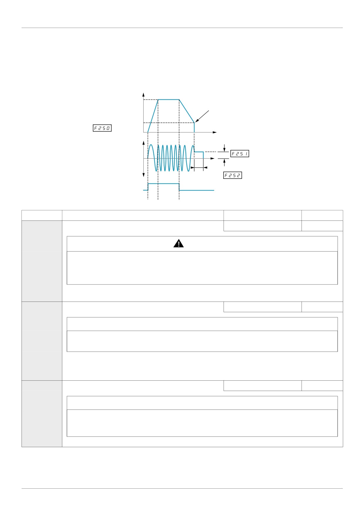
The drive can inject DC current into the motor to apply braking torque to the load. Parameters [DC brake start
freq.] (F250), [DC braking current] (F251) and [DC braking time] (F252) determine the Output Starting
Frequency, current level, and braking time.
During DC injection braking, the drive’s switching frequency is 6 kHz regardless of the setting of parameter
[Switch. freq. level] (F300) (see page 95).
Output Frequency (Hz)
Speed Reference
DC Braking
DC brake start freq.
0
Time (s)
DC Braking Current
Output Current
(A)
0
DC braking
time
Run Command
ON
OFF
Code
Name / Description
Adjustment range
Factory setting
F250
[DC brake start freq.]
0.0 to [Max frequency] (FH)
0.0 Hz
WARNING
NO HOLDING TORQUE
DC injection braking does not provide holding torque at zero speed.
DC injection braking does not work when there is a loss of power or when the drive detects a fault.
When necessary, use a separate brake to maintain torque levels.
Failure to follow these instructions can result in death, serious injury, or equipment damage.
When stopping the motor, the drive will apply DC injection braking once the output frequency drops below the level set
by parameter F250.
F251
[DC braking current] DC braking current level
0 to 100%
50% (1)
NOTICE
RISK OF DAMAGE TO THE MOTOR
Check that the motor will withstand this current without overheating.
Failure to follow this instruction can result in equipment damage.
Parameter F251 sets the level of current applied to the motor during DC injection braking. The displayed value, percent or
amperes, is set by parameter [Unit value selection] (F701) (see page 130).
During DC injection braking, the drive’s overload protection sensitivity increases. The drive automatically lowers the applied DC
current to avoid an overload detected fault.
F252
[DC braking time]
0.0 to 20.0 s
1.0 s
NOTICE
RISK OF DAMAGE TO THE MOTOR
Long periods of DC injection braking can cause overheating and damage the motor.
Protect the motor by avoiding long periods of DC injection braking.
Failure to follow this instruction can result in equipment damage.
Parameter F252 determines how long DC injection braking is applied to the motor.
(1) Percentage of the drive's rated current or ampere range. This will vary according to drive power rating.
98
I/O Control Parameters
I/O Control Parameters
8
What's in this Chapter?
This chapter contains the following topics:
Topic
Page
Logic Inputs Functions
100
Logic Input Function Compatibility
107
Relay Output Functions
108
Analog Input Functions
114
Analog Output Functions
115
Analog Input Adjustments
116
Active Logic Function
122
Preset Speeds
123
+/- Speed Control Parameters
124
Damper control
127
99
I/O Control Parameters
Logic Inputs Functions
See table on page 101 for a complete list of F, R and RES logic inputs assignments
Code
Name / Description
Adjustment range
Factory setting
F111
[LI F selection]
F Logic Input Function
0 to 73
2
The setting of parameter F111 determines the control function of logic input terminal F.
F112
[LI R selection]
R Logic Input Function
0 to 73
6
The setting of parameter F112 determines the control function of logic input terminal R.
F113
[LI RES selection] RES Logic Input Function
0 to 73
10
If [Driving Scroll] (F324) page 160 is set to [yes] (1) the setting is replaced by [Inverse Run permis.] (54).
The setting of parameter F113 determines the control function of logic input terminal RES.
F109
[VIA selection]
VIA Input Function (Analog or Logic Selection)
-
0
DANGER
UNINTENDED EQUIPMENT OPERATION
Prevent accidental grounding of logic inputs configured for sink logic. Accidental grounding can result in unin-
tended activation of drive functions.
Protect the signal conductors against damage that could result in unintentional conductor grounding.
Failure to follow these instructions will result in death or serious injury.
0
[AI]: Analog input
1
[LI sink]: Logic input - sink (negative logic)
2
[LI source]: Logic input - source (positive logic)
The setting of parameter F109 determines whether control input terminal VIA will serve as an analog input (0-10 Vdc or
0-20 mA) or as a logic input (either sink or source).
When configuring VIA as a logic input, be certain to slide switch SW100 on the main control board to the V (voltage) position.
When configuring VIA as a logic input using sink (negative) logic, be certain to connect a 4.7 k (1/2 W) resistor between control
terminals P24 and VIA.
For more information on the use of control input terminal VIA, see ATV212 Installation manual.
F118
[VIA LI selection]
VIA Logic Input Function
0 to 73
7
Set first parameter [VIA selection] (F109) before setting parameter F118. The setting of parameter F118 determines the
control function of logic input terminal VIA.
See page 101 for a complete list of VIA logic input assignments.
100
I/O Control Parameters
Logic inputs F, R, RES, and VIA (if parameter [VIA selection] (F109) is set to 1 or 2) can be set to the functions
described in the table below. See table on page 107 for logic input function compatibility.
Function
Action
No.
Description
0
[No assigned] No function
Logic input disabled
assigned
1
[Run permissive]
OFF: drive motor output disabled, motor coasts to stop
(see also input function
ON: drive ready for operation
54, page 105)
If [Logic Funct 2 active] (F110) is not set to 1 [Run permissive], a logic input should
be assigned to the [Run permissive] logic function to enable the motor to start.
2
[Forward]
Mode
Logic Input Action
2-wire control
OFF: Motor ramps down to a stop
(2-wire control: input
ON: Motor runs forward
function 49 NOT used)
or
Mode
Stop Input
Logic Input Action
(3-wire control: input
State
function 49 USED)
3-wire control
OFF
OFF: no function
ON: no function
3-wire control
ON
OFF to ON transition starts the drive, motor runs
forward
3
[Reverse]
Mode
Logic Input Action
2-wire control
OFF: Motor ramps down to a stop
(2-wire control: input func-
ON: Motor runs reverse
tion 49 NOT used)
or
Mode
Stop Input
Logic Input Action
(3-wire control: input
State
function 49 USED)
3-wire control
OFF
OFF: no function
ON: no function
3-wire control
ON
OFF to ON transition starts the drive, motor runs
in reverse
5
[Acc / Dec]
OFF: Acceleration/deceleration pattern 1
ON: Acceleration/deceleration pattern 2
6
[PS1]
Input 3
Input 2
Input 1
Motor Speed
Preset speed command
0
0
0
minimum speed or speed refer-
input 1
ence per [Frequency mode sel]
(FMOd)
0
0
1
Sr1: preset speed 1
7
[PS2]
0
1
0
Sr2: preset speed 2
Preset speed command
0
1
1
Sr3: preset speed 3
input 2
1
0
0
Sr4: preset speed 4
8
[PS3]
1
0
1
Sr5: preset speed 5
Preset speed command
1
1
0
Sr6: preset speed 6
input 3
1
1
1
Sr7: preset speed 7
10
[Fault reset] (see also
input function 55, page
DANGER
105)
UNINTENDED EQUIPMENT OPERATION
This configuration enables to reset the drive. Check this action will not endanger per-
sonnel or equipment in any way
Failure to follow these instructions will result in death or serious injury.
ON to OFF transition clears a detected fault (if cause of detected fault has been cleared)
11
[Ext Fault] (see also
OFF: No external detected fault
input function 45, page
ON: Motor stops according to method set by parameter [Ext. fault stop Mode] (F603)
104)
Embedded display terminal displays E detected fault, detected fault relay activated
101
I/O Control Parameters
Function
Action
No.
Description
13
[DC braking]
WARNING
NO HOLDING TORQUE
DC injection braking does not provide any holding torque at zero speed.
DC injection braking does not work when there is a loss of power or when the drive
detects a fault.
Where necessary, use a separate brake to maintain torque levels.
Failure to follow these instructions can result in death, serious injury, or equip-
ment damage.
OFF: No DC braking command
ON: DC braking applied to motor,
Level and time set by parameters [DC braking current] (F251) and
[DC braking time] (F252)
14
[PID disable]
OFF: PID control permitted
ON: PID control prohibited
PID control prohibited input terminal function is available to switch PID control and open-
loop control.
Also Clear PID integral value input terminal function (function 65) is available.
Note: For software version lower than V1.7IE04, when Clear PID integral value (function
65) and PID Control Prohibited (function 14) are used, it is necessary to set [Command
mode sel] (CMOd) to [Logic inputs] (O) Control terminal logic inputs.
15
[Param Edit]
OFF: Parameters locked (if parameter F700 = 1)
Functional only when pa-
ON: Programming changes permitted
rameter [Parameter lock]
(F700) = 1
16
[Run reset]
OFF: drive motor output disabled, motor coasts to stop
ON: drive ready for operation
ON to OFF transition clears a detected fault (if cause of detected fault has cleared)
20
[FW-RMP2]
OFF: Motor stops, ramping down per ACC/dEC pattern 2
Combination of forward
ON: Motor runs forward,
run command and accel-
ramping up per ACC/dEC pattern 2
eration/deceleration pat-
tern 2 selection
21
[Rev- RMP2]
OFF: Motor stops, ramping down per ACC/dEC pattern 2
Combination of reverse
ON: Motor runs in reverse, ramping up per ACC/dEC pattern 2
run command and accel-
eration/deceleration pat-
tern
2 selection
22
[FW, PS1]
OFF: Motor ramps down to a stop
Combination of forward
ON: Motor runs forward, at speed set by Sr1, preset speed 1
run command and preset
speed 1 command
23
[RV, PS1]
OFF: Motor ramps down to a stop
Combination of reverse
ON: Motor runs in reverse, at speed set by Sr1, preset speed 1
run command and preset
speed 1 command
24
[FW, PS2]
OFF: Motor ramps down to a stop
Combination of forward
ON: Motor runs forward, at speed set by Sr2, preset speed 2
run command and preset
speed 2 command
25
[RV, PS2]
OFF: Motor ramps down to a stop
Combination of reverse
ON: Motor runs in reverse, at speed set by Sr2, preset speed 2
run command and preset
speed 2 command
26
[FW, PS3]
OFF: Motor ramps down to a stop
Combination of forward
ON: Motor runs forward, at speed set by Sr3, preset speed 3
run command and preset
speed 3 command
102
I/O Control Parameters
Function
Action
No.
Description
27
[RV, PS3]
OFF: Motor ramps down to a stop
Combination of reverse
ON: Motor runs in reverse, at speed set by Sr3, preset speed 3
run command and preset
speed 3 command
30
[FW-RMP2-SP1]
OFF: Motor stops, ramping down per ACC/dEC pattern 2
Combination of forward
ON: Motor runs forward, at speed set by Sr1, preset speed 1,
run command, preset
ramping up per ACC/dEC pattern 2
speed 1 command, and
acceleration/deceleration
pattern 2 selection
31
[Rev-RMP2-SP1]
OFF: Motor stops, ramping down per ACC/dEC pattern 2
Combination of reverse
ON: Motor runs in reverse, at speed set by Sr1, preset speed 1,
run command, preset
ramping up per ACC/dEC pattern 2
speed 1 command, and
acceleration/deceleration
pattern 2 selection
32
[FW-RMP2-SP2]
OFF: Motor stops, ramping down per ACC/dEC pattern 2
Combination of forward
ON: Motor runs forward, at speed set by Sr2, preset speed 2,
run command, preset
ramping up per ACC/dEC pattern 2
speed 2 command, and
acceleration/deceleration
pattern 2 selection
33
[Rev-RMP2-SP2]
OFF: Motor stops, ramping down per ACC/dEC pattern 2
Combination of reverse
ON: Motor runs in reverse, at speed set by Sr2, preset speed 2,
run command, preset
ramping up per ACC/dEC pattern 2
speed 2 command, and
acceleration/deceleration
pattern 2 selection
34
[FW-RMP2-SP3]
OFF: Motor stops, ramping down per ACC/dEC pattern 2
Combination of forward
ON: Motor runs forward, at speed set by Sr3, preset speed 3,
run command, preset
ramping up per ACC/dEC pattern 2
speed 3 command, and
acceleration/deceleration
pattern 2 selection
35
[Rev-RMP2-SP3]
OFF: Motor stops, ramping down per ACC/dEC pattern 2
Combination of reverse
ON: Motor runs in reverse, at speed set by Sr3, preset speed 3,
run command, preset
ramping up per ACC/dEC pattern 2
speed 3 command, and
acceleration/deceleration
pattern 2 selection
38
[Frequency source]
OFF: drive follows speed reference set by parameter [Frequency mode sel] (FMOd)
Frequency reference
ON: drive follows speed reference set by parameter [Remote spd ref 2] (F207) >
source switching
(if [Auto/man speed ref] (F200) = 1)
39
[Motor switch]
NOTICE
RISK OF DAMAGE TO THE MOTOR
The motor switching function disables motor thermal protection.
The use of external overload protection is required when using motor switching.
Failure to follow these instructions can result in death, serious injury, or equip-
ment damage.
OFF: 1st motor V/Hz parameter set active:
([Mot cont. mode sel.] (Pt), [Motor rated freq.] (uL), [Motor rated voltage] (uLu), [Mot
Voltage Boost] (ub), [Motor thermal prot.] (tHr))
ON: 2nd motor V/Hz parameter set active:
(Pt = 0, F170, F171, F172, F173)
103
I/O Control Parameters
Function
Action
No.
Description
40
[Mot param. switch]
Motor control parameter
NOTICE
switching V/Hz, current
limit, acceleration/decel-
RISK OF DAMAGE TO THE MOTOR
eration pattern
The parameter switching function disables motor thermal protection.
The use of external overload protection is required when using motor switching.
Failure to follow these instructions can result in death, serious injury, or equip-
ment damage.
OFF: 1st motor control parameter set active:
([Mot cont. mode sel.] (Pt), [Motor rated freq.] (uL), [Motor rated voltage] (uLu), [Mot
Voltage Boost] (ub), [Motor thermal prot.] (tHr), [Acceleration time 1] (ACC), [Decel-
eration time 1] (dEC), [Acc/dec 1 pattern] (F502), [Motor Current Limit] (F601))
ON: 2nd motor control parameter set active:
(Pt = 0, F170, F171, F172, F173, F185, F500, F501, F503)
41
[(+) speed]
OFF: No motor speed increase
ON: Motor accelerates
42
[(-) speed]
OFF: No motor speed reduction
ON: Motor decelerates
43
[+/- clear]
OFF to ON transition clears frequency level set by +/- speed inputs
44
[+/- SPD, FLT CLR]
OFF to ON transition clears frequency level set by +/- speed inputs
ON to OFF transition clears a detected fault (if cause of detected fault has been cleared)
45
[Inv Ext. fault]
OFF: Motor stops according to method set by parameter [Ext. fault stop Mode] (F603)
Inversion of external de-
Embedded display terminal displays E detected fault
tected fault signal (see
ON: No external detected fault
also input function 11,
page 101)
46
[Ext. Th fault]
OFF: No external overheating
External overheating in-
ON: Motor stops, embedded display terminal displays OH2
put (see also input func-
tion 47)
47
[Inv Ext. Th fault]
OFF: Motor stops, embedded display terminal displays OH2
Inversion of external over-
ON: No external overheating
heating input (see also in-
put function 46)
48
[Forced local]
OFF: No forced local function
ON: Control of the drive is forced to mode set by [Frequency mode sel] (FMOd), [Com-
mand mode sel] (CMOd), and [Remote spd ref 2] (F207).
49
[3-wire]
OFF: Motor ramps down to a stop
ON: drive ready for operation
51
[Reset kWh]
OFF: No function
Clear accumulated power
ON: Clears kWh memory
consumption kWh display
52
[Forced mode]
DANGER
LOSS OF PERSONNEL AND EQUIPMENT PROTECTION
When F650 is set to 1 or 2 and a logic input set to function "52" is activated, all the
drive controller protection will be disable.
• Logic input should not be enable on function 52 for typical applications...
• Logic input should be enable on function 52 only in extraordinary situations where
a thorough risk analysis demonstrates that the presence of adjustable speed drive
protection poses a greater risk than personnel injury or equipment damage.
Failure to follow these instructions will result in death or serious injury.
This function enables the "Forced fire" mode.
In this mode, all the detected fault will be ignored or if it is a hardware trip, the drive will
be reset to try to restart.
OFF: No function
ON: Motor runs at speed set by F294
Note: F650, F659 and F294 must be configured to activate this function.
104
I/O Control Parameters
Function
Action
No.
Description
53
[Fire mode]
This function enables the "Fire" mode
OFF: No function
ON: Motor runs at speed set by F294
Note: F650, F659 and F294 must be configured to activate this function.
54
[Inverse Run permis.]
OFF: drive ready for operation
Inversion of run permis-
ON: drive motor output disabled, motor coasts to stop
sive (see also input func-
This mode allows to have a freewheel stop using a terminal command.
tion 1 page 101)
55
[Inv fault reset]
Inversion of clear detect-
DANGER
ed fault (see also input
function 10 page 101)
UNINTENDED EQUIPMENT OPERATION
This configuration enables to reset the drive. Check this action will not endanger per-
sonnel or equipment in any way
Failure to follow these instructions will result in death or serious injury.
OFF to ON transition clears a detected fault (if cause of detected fault has been cleared)
56
[Run, FW]
OFF: drive motor output disabled, motor coasts to stop
Combination of run per-
ON: Motor runs forward
missive and run forward
command (2-wire control
only)
57
[Run, RV]
OFF: drive motor output disabled, motor coasts to stop
Combination of run per-
ON: Motor runs reverse
missive and run reverse
command (2-wire control
only)
61
[I limit 1/2]
OFF: Current limit level 1 [Motor Current Limit] (F601) selected
Current limit level selec-
ON: Current limit level 2 [Mot. 2 current limit] (F185) selected
tion
62
[RY on]
OFF: Normal real-time relay operation
Holding of RYA-RYC
ON: RYA-RYC is held on once activated
relay output
64
[Cancel HMI cmd]
OFF: Last graphic display option command cancelled
Cancellation of last
ON: Last graphic display option command retained
graphic display option
command
65
[PID integral]
OFF: No action
Clear PID integral value
ON: PID integral value held at zero
66
[Run-fw-sp1]
OFF: drive motor output disabled, motor coasts to stop
Combination of run per-
ON: Motor runs forward at speed set by Sr1, preset speed 1
missive, run forward com-
mand, and preset speed 1
command
67
[Run-rev-sp1]
OFF: drive motor output disabled, motor coasts to stop
Combination of run per-
ON: Motor runs reverse at speed set by Sr1, preset speed 1
missive, run reverse com-
mand, and preset speed 1
command
68
[Run-fw-sp2]
OFF: drive motor output disabled, motor coasts to stop
Combination of run per-
ON: Motor runs forward at speed set by Sr2, preset speed 2
missive, run forward com-
mand, and preset speed 2
command
69
[Run-rev-sp2]
OFF: drive motor output disabled, motor coasts to stop
Combination of run per-
ON: Motor runs reverse at speed set by Sr2, preset speed 2
missive, run reverse com-
mand, and preset speed 2
command
105
I/O Control Parameters
Function
Action
No.
Description
70
[Run-fw-sp4]
OFF: drive motor output disabled, motor coasts to stop
Combination of run per-
ON: Motor runs forward at speed set by Sr4, preset speed 4
missive, run forward com-
mand, and preset speed 4
command
71
[Run-rev-sp4]
OFF: drive motor output disabled, motor coasts to stop
Combination of run per-
ON: Motor runs reverse at speed set by Sr4, preset speed 4
missive, run reverse com-
mand, and preset speed 4
command
72
[PID rev]
OFF: if F111 = 72 and F terminal is OFF, PI error input = reference - feedback
PID error signal reversed
ON: if F111 = 72 and F terminal is ON, PI error input = feedback - reference
73
[Damper feedBack]
OFF: if F111 or F112 or F113 is not set to 73 the damper has no effect.
ON: if F111 or F112 or F113 = 73 the damper is ON.
The damper feedback has not effect if not configured to an output.
106
I/O Control Parameters
Logic Input Function Compatibility
O = Compatible
X = Incompatible
+ = Compatible under some conditions
@ = Priority
Function No. / Function
1/54
2
3
5
6-9
10/55
11/45
13
14
15
46/47
48
41-43
49
38
39
40
52/53
[No assigned] / [Inverse Run
1/54
@
@
@
@
O
O
@
O
O
O
O
O
@
O
O
O
X
permissive]
2
[Forward]
+
X
O
O
O
X
X
O
O
X
O
O
X
O
O
O
X
3
[Reverse]
+
+
O
O
O
X
X
O
O
X
O
O
X
O
O
O
X
5
[Acc / Dec]
+
O
O
O
O
X
X
O
O
X
O
O
O
O
O
X
O
6~8
[PS1]~[PS3]
+
O
O
O
O
X
X
O
O
X
O
O
O
O
O
O
X
10/55
[Fault reset] / [Inv fault reset]
O
O
O
O
O
X
O
O
O
X
O
O
O
O
O
O
X
11/45
[Ext. fault] / [Inv. Ext. fault]
+
@
@
@
@
@
@
@
O
+
O
@
@
O
O
O
X
13
[DC braking]
+
@
@
@
@
O
X
@
O
X
O
@
@
O
O
O
X
14
[PID disable]
O
O
O
O
O
O
X
X
O
X
O
O
O
O
O
O
X
15
[Param Edit]
O
O
O
O
O
O
O
O
O
O
O
O
O
O
O
O
O
[Ext. Th fault] / [Inv Ext. Th
46/47
@
@
@
@
@
@
+
@
@
O
O
O
@
O
O
O
X
fault]
48
[Forced local]
O
O
O
O
O
O
O
O
O
O
O
O
O
O
O
O
X
[(+) speed]
41-43
O
O
O
O
O
O
O
O
O
O
O
O
O
O
O
O
X
[(-) speed]
[+/- clear]
49
[3-wire]
+
@
@
O
O
O
X
X
O
O
X
O
O
O
O
O
X
38
[Frequency source]
O
O
O
O
O
O
O
O
O
O
O
O
O
O
O
O
X
39
[Motor switch]
O
O
O
O
O
O
O
O
O
O
O
O
O
O
O
X
O
40
[Mot param. switch]
O
O
O
@
O
O
O
O
O
O
O
O
O
O
O
@
O
52/53
[Forced mode] / [Fire mode]
@
@
@
O
@
@
@
@
@
O
@
@
@
@
@
O
O
The following logic input functions are active, regardless of the [Frequency mode sel] (FMOd) and [Command
mode sel] (CMOd) setting.
(1) Run permissive
(10) Clear detected fault
(11) External detected fault
When determining function compatibility using the table above, the function listed horizontally is activated first
and the function listed vertically is activated second.
107
I/O Control Parameters
Relay Output Functions
The two relay outputs (FL and RYA-RYC) can be set to the functions described in the table below.
Function No. / Description
Action
0
[Low speed reach]
OFF: output frequency is low speed setting [Low limit frequency] (LL)
Low speed reached
ON: output frequency is > low speed setting LL
1
[Inv low spd reach]
OFF: output frequency is > low speed setting [Low limit frequency] (LL)
Inversion of low speed reached
ON: output frequency is low speed setting LL
2
[High speed reach]
OFF: output frequency is < high speed setting [Upper limit freq] (UL)
High speed reached
ON: output frequency is high speed setting UL
3
[Inv Hi spd reach]
OFF: output frequency is high speed setting [Upper limit freq] (UL)
Inversion of high speed reached
ON: output frequency is < high speed setting UL
4
[F100 speed reach]
OFF: output frequency is < [Freq. 1 reached] (F100) speed setting
F100 speed reached (See page
ON: output frequency is F100 speed setting
125 for more details on parameter
F100)
5
[Inv F100 sp reach]
OFF: output frequency is [Freq. 1 reached] (F100) speed setting
Inversion of F100 speed reached
ON: output frequency is < F100 speed setting
6
[Speed reach]
OFF: output frequency is commanded speed +/- [Freq.2 bandw.] (F102)
Commended speed reached
hysteresis band
ON: output frequency is > commanded speed +/- F102 hysteresis band
7
[Inv speed reach]
OFF: output frequency is > commanded speed +/- [Freq.2 bandw.]
Inversion of commanded speed
(F102) hysteresis band
reached
ON: output frequency is commanded speed +/- F102 hysteresis band
8
[F101 speed reach]
OFF: output frequency is [Freq. 2 reached] (F101) speed +/- [Freq.2
F101 speed reached (See page
bandw.] (F102) hysteresis band
125 for more details on parameters
ON: output frequency is > F101 speed +/- F102 hysteresis band
F101 and F102.)
9
[Inv F101 sp reach]
OFF: output frequency is > [Freq. 2 reached] (F101) speed +/- [Freq.2
Inversion of F101 speed reached
bandw.] (F102) hysteresis band
ON: output frequency is F101 speed +/- F102 hysteresis band
10
[Drive fault]
OFF: No drive detected fault
Fault relay. The drive is not in a fault
ON: drive detected fault
state during auto fault reset attempts.
See also function 36 page 112.
WARNING
LOSS OF CONTROL
When F130, F132, F137 is set to 10, the output will be active
when the drive will detect a fault.
The drive status will not be detected if the wiring is damaged for any
reason.
Do not select10 unless you are sure that your signal will be present
in any case.
Failure to follow these instructions can result in death, serious inju-
ry, or equipment damage.
11
[No drive fault]
OFF: drive detected fault
Inversion of Drive fault function.
ON: No drive detected fault
12
[Overload flt]
OFF: Estimated motor torque has NOT been at [Overtorque level]
Overtorque fault
(F616) level for a time period longer than that set by [Ovtorque det
Overtorque fault detection is active
time] (F618)
only if parameter F615 = 1. See
ON: Estimated motor torque has been at F616 level for a time period
page 143 for more detail on an
longer than that set by F618. drive stopped, displaying Ot
overtorque detected fault and
parameters F616 and F618.)
13
[Inv overload flt]
OFF: Estimated motor torque has been at [Overtorque level] (F616)
Inversion of Overload flt function
level for a time period longer than that set by [Ovtorque det time]
(F618). drive stopped, displaying Ot
ON: Estimated motor torque has NOT been at F616 level for a time
period longer than that set by F618
108

I/O Control Parameters
Function No. / Description
Action
14
[Drive running]
OFF: drive is not powering the motor
Run relay
ON: drive is powering the motor, accelerating, decelerating, at constant
speed, or DC braking
15
[Drive no run]
OFF: drive is powering the motor, accelerating, decelerating, at constant
Inversion of Drive no run function
speed, or DC braking
ON: drive is not powering the motor
16
[Motor overload]
OFF: motor thermal state is < 50% of motor overload detected fault level
Motor overload alarm detection is only
ON: motor thermal state is 50% of motor overload detected fault level
active if parameter OLM is set to
either 0, 1, 4, or 5. See page 146 for
more detail on motor overload
protection settings.
17
[Inv mot. overload]
OFF: motor thermal state is 50% of motor overload detected fault level
Inversion of Motor overload function
ON: motor thermal state is < 50% of motor overload detected fault level
20
[Torque alarm]
OFF: Estimated motor torque is < 70% of F616 level minus F619
Overtorque alarm detection is active
hysteresis band
only if parameter F615 = 0. See
ON: Estimated motor torque is 70% of F616 level
page 143 for more detail on the over-
torque alarm and parameters [Over-
torque level] (F616), [Overtorque
band] (F619).
21
[Inv torque alarm]
OFF: Estimated motor torque is 70% of [Overtorque level] (F616) level
Inversion of Torque alarm function
ON: Estimated motor torque is < 70% of F616 level minus
[Overtorque band] (F619) hysteresis band
22
[Gen. alarm]
OFF: No detected fault condition from the sources listed below exists
General alarm
ON: A detected fault has been issued by one of the following sources:
• Overtorque detected fault (output functions 12 and 13)
• Motor overload (output functions 16 and 17)
• Overtorque detected fault (output functions 20 and 21)
• Load detection loss (output functions 24 and 25)
• Run time (output functions 42 and 43)
• Undervoltage (output functions 54 and 55)
• drive in sleep mode (see for more detail on parameter F256)
• Power loss (see for more detail on parameter F302)
• Overcurrent - motor current limit level (parameter F601)
• Overvoltage - DC bus voltage overvoltage stall level (parameter
F626)
• Drive overheating
23
[Inv gen. alarm]
OFF: A detected fault has been issued by one of the following sources:
Inversion of General alarm function
• Overtorque detected fault (output functions 12 and 13)
• Motor overload (output functions 16 and 17)
• Overtorque detection loss (output functions 20 and 21)
• Failure of load detection (output functions 24 and 25)
• Run time (output functions 42 and 43)
• Undervoltage (output functions 54 and 55)
• Drive in sleep mode (see for more detail on parameter F256)
• Power loss (see for more detail on parameter F302)
• Overcurrent - motor current limit level (parameter F601)
• Overvoltage - DC bus voltage overvoltage stall level (parameter
F626)
• drive overheating
ON: No alarm condition from the sources listed above exists
24
[Underload detect.]
OFF: Motor current is greater than F611 level + F609 hysteresis band
(See page 141 for more detail on pa-
ON: Motor current is less than F611 level for the time set by F612
rameters F609 - F612 and the
underload function.)
25
[Inv underl. det.]
OFF: Motor current is less than F611 level for the time set by F612
Inversion of Underload detect. func-
ON: Motor current is greater than F611 level + F609 hysteresis band
tion
109

I/O Control Parameters
Function No. / Description
Action
26
[Manu reset flt.]
OFF: None of the detected fault conditions listed below exist
Non-autoresettable detected fault
ON: One (or more) of the following detected fault conditions exists and has
stopped the drive:
• E - external detected fault
• E-18 - VIA analog input signal detected fault
• E-19 - main control board CPU communication
• E-20 - excessive torque boost
• E-21 - main control board CPU detected fault 2
• EEP1 - main control board EEPROM detected fault 1
• EEP2 - main control board EEPROM detected fault 2
• EEP3 - main control board EEPROM detected fault 3
• EF2 - ground detected fault
• EPH0 - output phase detected fault detection
• EPH1 - input phase detected fault detection
• Err1 - speed reference
• Err2 - main control board RAM
• Err3 - main control board ROM
• Err4 - main control board CPU detected fault 1
• Err5 - serial communication control
• Err7 - motor current sensor
• Err8 - serial communication network
• Err9 - graphic display option communication interruption
• Etn1 - auto-tuning
• EtYP - drive ratings
• OCA - short-circuit detected in drive output inverter stage
during motor startup
• OCL - short-circuit detected in motor or output wiring during
motor startup
• OH2 - external overheating
• Ot - overtorque
• Uc - underload
• UP1 - Undervoltage
27
[Inv manu reset flt.]
OFF: One (or more) of the following fault conditions exists and has stopped
Inversion of Manu reset flt. function
the drive:
• E - external detected fault
• E-18 - VIA analog input signal
• E-19 - main control board CPU communication
• E-20 - excessive torque boost
• E-21 - main control board CPU detected fault 2
• EEP1 - main control board EEPROM detected fault 1
• EEP2 - main control board EEPROM detected fault 2
• EEP3 - main control board EEPROM detected fault 3
• EF2 - ground fault
• EPH0 - output phase loss detection
• EPH1 - input phase loss detection
• Err1 - speed reference
• Err2 - main control board RAM
• Err3 - main control board ROM
• Err4 - main control board CPU detected fault 1
• Err5 - serial communication control
• Err7 - motor current sensor
• Err8 - serial communication network
• Err9 - graphic display option communication interruption
• Etn1 - auto-tuning
• EtYP - drive ratings
• OCA - short-circuit detected in drive output inverter stage
during motor startup
• OCL - short-circuit detected in motor or output wiring during
motor startup
• OH2 - external overheating
• Ot - overtorque
• Uc - underload
• UP1 - Undervoltage
ON: None of the detected fault conditions listed above exist
110
I/O Control Parameters
Function No. / Description
Action
28
[Auto-reset fault]
OFF: None of the detected fault conditions listed below exist
Auto-clear detected fault
ON: One (or more) of the following detected fault conditions exists:
• Fd1 - damper detected fault 1 (closed damper)
Note: Relay activates when
• Fd2 - damper detected fault 2 (opened damper)
maximum number of autoclear set
• OC1 - overcurrent during acceleration
by [Number auto reset] (F303)
• OC2 - overcurrent during deceleration
page 135 is reached.
• OC3 - overcurrent during constant speed
• OC1P - Short circuit or ground detected fault during
acceleration
• OC2P - Short circuit or ground detected fault during
deceleration
• OC3P - Short circuit or ground detected fault during constant
speed
• OH - drive overheating
• OL1 - drive overload
• OL2 - motor overload
• OP1 - overvoltage during acceleration
• OP2 - overvoltage during deceleration
• OP3 - overvoltage during constant speed
29
[Inv auto-reset flt]
OFF: One (or more) of the following detected fault conditions exists:
Inversion of Auto-reset fault function
• Fd1 - damper detected fault 1 (closed damper)
• Fd2 - damper detected fault 2 (opened damper)
Note: Relay deactivates when
• OC1 - overcurrent during acceleration
maximum number of autoclear set
• OC2 - overcurrent during deceleration
by [Number auto reset] (F303)
• OC3 - overcurrent during constant speed
page 135 is reached.
• OC1P - Short circuit or ground detected fault during
acceleration
• OC2P - Short circuit or ground detected fault during
deceleration
• OC3P - Short circuit or ground detected fault during constant
speed
• OH - drive overheating
• OL1 - drive overload
• OL2 - motor overload
• OP1 - overvoltage during acceleration
• OP2 - overvoltage during deceleration
• OP3 - overvoltage during constant speed
ON: None of the detected fault conditions listed above exist
30
[Drive rdy 1]
OFF: drive not ready for operation
drive ready condition 1
ON: drive ready for operation (ready includes active run permissive and ac-
tive run command)
31
[Inv drive rdy 1]
OFF: drive ready for operation (ready includes active run permissive and
Inversion of Drive rdy 1 function
active run command)
ON: drive not ready for operation
32
[Drive rdy 2]
OFF: drive not ready for operation
drive ready condition 2
ON: drive ready for operation (ready does not include active run permissive
or active run command)
33
[Inv drive rdy 2]
OFF: drive ready for operation (ready does not include active run permis-
Inversion of Drive rdy 2 function
sive or active run command)
ON: drive not ready for operation
34
[VIB ref source]
OFF: analog input terminal VIB is NOT the active speed reference source
VIB input reference source
ON: VIB is the active speed reference source
35
[Inv VIB ref source]
OFF: analog input terminal VIB is the active speed reference source
Inversion of VIB ref source function
ON: VIB is NOT the active speed reference source
111
I/O Control Parameters
Function No. / Description
Action
36
[Fault relay]
(The drive is not in a fault state during
WARNING
auto clear detected fault attempts.
See also function 10 page 108)
LOSS OF CONTROL
When F130, F132, F137 is set to 36, the output will be active
when the drive will detect a fault.
The drive status will not be detected if the wiring is damaged for any
reason.
Do not select 36 unless you are sure that your signal will be present
in any case.
Failure to follow these instructions can result in death, serious inju-
ry, or equipment damage.
OFF: No drive detected fault
ON: drive detected fault.
Relay activates when a clearable fault occurs and the drive attempts to re-
start. Relay deactivates when drive is restarting.
37
[Inv fault relay]
OFF: drive detected fault
Inversion of Fault relay function 36
ON: No drive detected fault
Relay deactivates when a clearable fault occurs and the drive attempts to
restart. Relay activates when drive is restarting.
38
[Ser. data relay FL]
OFF: Serial communication word FA50 bit 0 = 0
Serial communication data
ON: Serial communication word FA50 bit 0 = 1
39
[Inv ser. dat rel. FL]
OFF: Serial communication word FA50 bit 0 = 1
Inversion of ser. dat rel. FL function
ON: Serial communication word FA50 bit 0 = 0
40
[Ser. data relay RY]
OFF: Serial communication word FA50 bit 1 = 0
Serial communication data
ON: Serial communication word FA50 bit 1 = 1
41
[Inv ser. dat rel RY]
OFF: Serial communication word FA50 bit 1 = 1
Inversion of ser. dat rel. RY function
ON: Serial communication word FA50 bit 1 = 0
42
[Drive run time al]
OFF: Run time is < F621 time setting
Drive operational run time alarm
ON: Run time is F621 time setting
(see page 130 for more detail on
parameter F621).
43
[Inv.drive run time al] Inversion of Drive
OFF: Run time is F621 time setting
run time al function
ON: Run time is < F621 time setting
44
[Drive serv. alarm]
OFF: drive maintenance detected fault not active
Drive service alarm (see page 144
ON: drive maintenance detected fault active
for more detail on parameter
F634).
45
[Inv. drive serv. alarm] Inversion of
OFF: drive maintenance detected fault active
Drive serv. alarm function
ON: drive maintenance detected fault not active
48
[LI F state]
OFF: Logic input F is not active
Logic input F state
ON: Logic input F is active
49
[Inv. LI F state] Inversion of LI F state
OFF: Logic input F is active
function
ON: Logic input F is not active
50
[LI R state]
OFF: Logic input R is not active
Logic input R state
ON: Logic input R is active
51
[Inv. LI R state] Inversion of LI R state
OFF: Logic input R is active
function
ON: Logic input R is not active
52
[Speed ref = VIA]
OFF: Speed reference from the source identified by
Drive speed reference equals VIA sig-
[Frequency mode sel] (FMOd) or the source identified by
nal
[Remote spd ref 2] (F207) VIA signal
ON: Speed reference from the source identified by FMOd or the source
identified by F207 = VIA signal
53
[Inv. speed ref = VIA] Inversion of
OFF: Speed reference from the source identified by
Speed ref = VIA function
[Frequency mode sel] (FMOd) or the source identified by
[Remote spd ref 2] (F207) = VIA signal
ON: Speed reference from the source identified by FMOd or the source
identified by F207 VIA signal
112
I/O Control Parameters
Function No. / Description
Action
54
[Undervolt. alarm]
OFF: Undervoltage detected fault is not active
Undervoltage alarm
ON: Undervoltage detected fault is active
55
[Inv. undervolt. alarm] Inversion of Un-
OFF: Undervoltage detected fault is active
dervolt. al. function
ON: Undervoltage detected fault is not active
56
[Loc / remote]
OFF: drive is in remote mode
Local/remote switching
ON: drive is in local mode
57
[Inv. loc / remote] Inversion of Loc / re-
OFF: drive is in local mode
mote function
ON: drive is in remote mode
58
[PTC alarm]
OFF: Motor temperature as indicated by PTC thermal probes is < 60% of
PTC thermal alarm
the detected fault level
ON: Motor temperature as indicated by PTC thermal probes is 60% of the
detected fault level
59
[Inv. PTC alarm] Inversion of PTC
OFF: Motor temperature as indicated by PTC thermal probes is 60% of the
alarm function
detected fault level
ON: Motor temperature as indicated by PTC thermal probes is < 60% of the
detected fault level
60
[Speed ref = VIB]
OFF: Speed reference from the source identified by
Drive speed reference equals VIB sig-
[Frequency mode sel] (FMOd) or the source identified [Remote spd ref 2]
nal
(F207) VIB signal
ON: Speed reference from source identified by FMOd or the source iden-
tified F207 = VIB signal
61
[Inv. speed ref = VIB] Inversion of
OFF: Speed reference from source identified by
Speed ref = VIB function
[Frequency mode sel] (FMOd) or the source identified [Remote spd ref 2]
(F207) = VIB signal
ON: Speed reference from the source identified by FMOd or the source
identified F207 VIB signal
62
[VIA detection]
ON: The value of VIA is equal to or higher than F160 + F161
Analog VIA detection
OFF: The value of VIA is equal to or lower than F160 - F161
63
[Inv. VIA detection] Inversion of VIA
ON: The value of VIA is equal to or lower than F160 - F161
detection function
OFF: The value of VIA is equal to or higher than F160 + F161
64
[VIB detection]
ON: The value of VIB is equal to or higher than F162 + F163
Analog VIB detection
OFF: The value of VIB is equal to or lower than F162 - F163
65
[Inv. VIB detection] Inversion of VIB
ON: The value of VIB is equal to or lower than F162 - F163
detection function
OFF: The value of VIB is equal to or higher than F162 + F163
66
[Freq. reach hyst]
ON: The ouptput frequency is equal to or higher than F101 + F102
Set frequency attainment signal with
OFF: The ouptput frequency is equal to or lower than F101 - F102
hysteresis
(See page 125 for more detail on parameters F101 and F102.)
67
[Inv. freq. reach hyst] Inversion of
ON: The ouptput frequency is equal to or lower than F101 - F102
Freq. reach hyst function
OFF: The ouptput frequency is equal to or higher than F101 + F102
(See page 125 for more detail on parameters F101 and F102.)
68
[Damper]
ON: The damper is ON.
Damper control
OFF: The damper is OFF (see page 127)
69
[Inv. damper] Inversion of Damper
ON: The damper is OFF.
function
OFF: The damper is ON (see page 127)
70
[DisOil Inj PL] Disable oil injection in
Positive logic
high speed positive logic
71
[DisOil Inj NL] Disable oil injection in
Negative logic
high speed negative logic
254
[Relay OFF]
OFF
Relay output is OFF
255
[Relay ON]
ON
Relay output is ON
113
I/O Control Parameters
Analog Input Functions
Two analog inputs are supplied with the ATV212 drive. The terminals are designated VIA and VIB.
Analog Input VIA
VIA can accept the following signal types:
- Voltage (V): 0-10 V, voltage or potentiometer input
- Current (I): 0-20 mA or 4-20 mA
The signal type (V or I) is selected by setting SW100 on the main control board.
For information on wiring, consult the ATV212 Installation manual.
The slope and bias of the input signal are adjusted with parameters F201-F204 and F470-F471.
For more information, see page 116.
VIA is configured as the speed reference input in the following macro-configurations:
- Run permissive
- 3-wire
- 4-20 mA.
Relay output functions 34 and 35 can signal when VIA is being used as the speed reference source. For more
information, see table on page 111 and consult “I/O Control Parameters” on page 100.
Relay output functions 52 and 53 can be used to signal the results of a comparison between the signal at VIA
and the speed reference commanded by [Frequency mode sel] (FMOd) or [Remote spd ref 2] (F207).
This function can also be used to send out a signal indicating whether the amount of processing and the
amount of feedback agree with each other. For more information, see table on page 108. Also, consult “I/O
Control Parameters” on page 100 and review information about parameter F167 on page 126.
The drive can enter a detected fault state if the VIA signal drops below a specified level for more than 300
mS. For more information, see parameter F633 on page 141 and code E-18 on page 180.
VIA can serve as an analog or a logic input, depending on setting of parameter F109 (set to 0 for analog
input). Analog input is the factory setting. See page 100 for more information about parameter F109.
Analog Input VIB
VIB can accept the following signal types:
Voltage (V): 0-10V, voltage or potentiometer input
PTC motor thermal sensor input. For more information, see parameters F645 and F646 on page 122.
Adjust the slope and bias of the input signal with parameters F210 - F213 and F472 - F473. For
more information, see page 116.
Relay output functions 52 and 53 can signal when VIA is being used as the speed reference source. For more
information, see table on page 112 and consult “I/O Control Parameters” on page 100.
Relay output functions 60 and 61 can be used to signal the results of a comparison between the signal at VIB
and the speed reference commanded by [Frequency mode sel] (FMOd) or [Remote spd ref 2] (F207).
This function can also be used to send out a signal indicating whether the amount of processing and the
amount of feedback agree with each other. For more information, see table on page 108. Also, consult “I/O
Control Parameters” on page 100 and review information about parameter F167 on page 126.
General
The selection of VIA or VIB as the speed reference input in remote mode is made through parameters
[Frequency mode sel] (FMOd) and [Remote spd ref 2] (F207). FMOd is the primary speed reference
source, while F207 is the secondary source. Switching between the two is determined by the setting of
parameter [Auto/man speed ref] F200. For more information, see page 118.
Analog output terminal FM can be configured to provide a signal in proportion to the VIA or VIB signal levels.
See parameter FMSL, selections 13 and 14, on page 118.
When PID control is enabled, VIA or VIB can serve as the setpoint input. Either VIA or VIB needs to be
selected as the feedback input. See page 120 for more information on parameter F360 and PID control.
Information can be transferred between the serial communication network and the analog inputs via read and
write functions F870, F871, and F875-F879. For more information, see pages 150 to 151.
114
I/O Control Parameters
Analog Output Functions
One analog output is supplied with the ATV212 drive. The terminal is designated FM.
FM is a multifunctional programmable analog output supplying an output frequency signal as the factory default.
The FM terminal can output a voltage or current signal.
When switch SW101 is set to V (voltage), FM outputs a 0-10 Vdc signal at 1 mA.
When switch SW101 is set to I (current), FM outputs a 0-20 mA signal up to 24 Vdc. For detail on proper
wiring, consult the ATV212 Installation manual.
The drive value represented by the FM analog output signal is determined by the setting of parameter
[AO funct. selection] (FMSL) (see page 118).
Calibrating the FM signal output to provide full scale deflection on an analog meter is achieved by adjusting
parameter [AO scaling] (FM) (see page 118).
The slope and bias of the FM analog output signal can be adjusted using parameters F691 and F692. For
more information, see page 119.
115
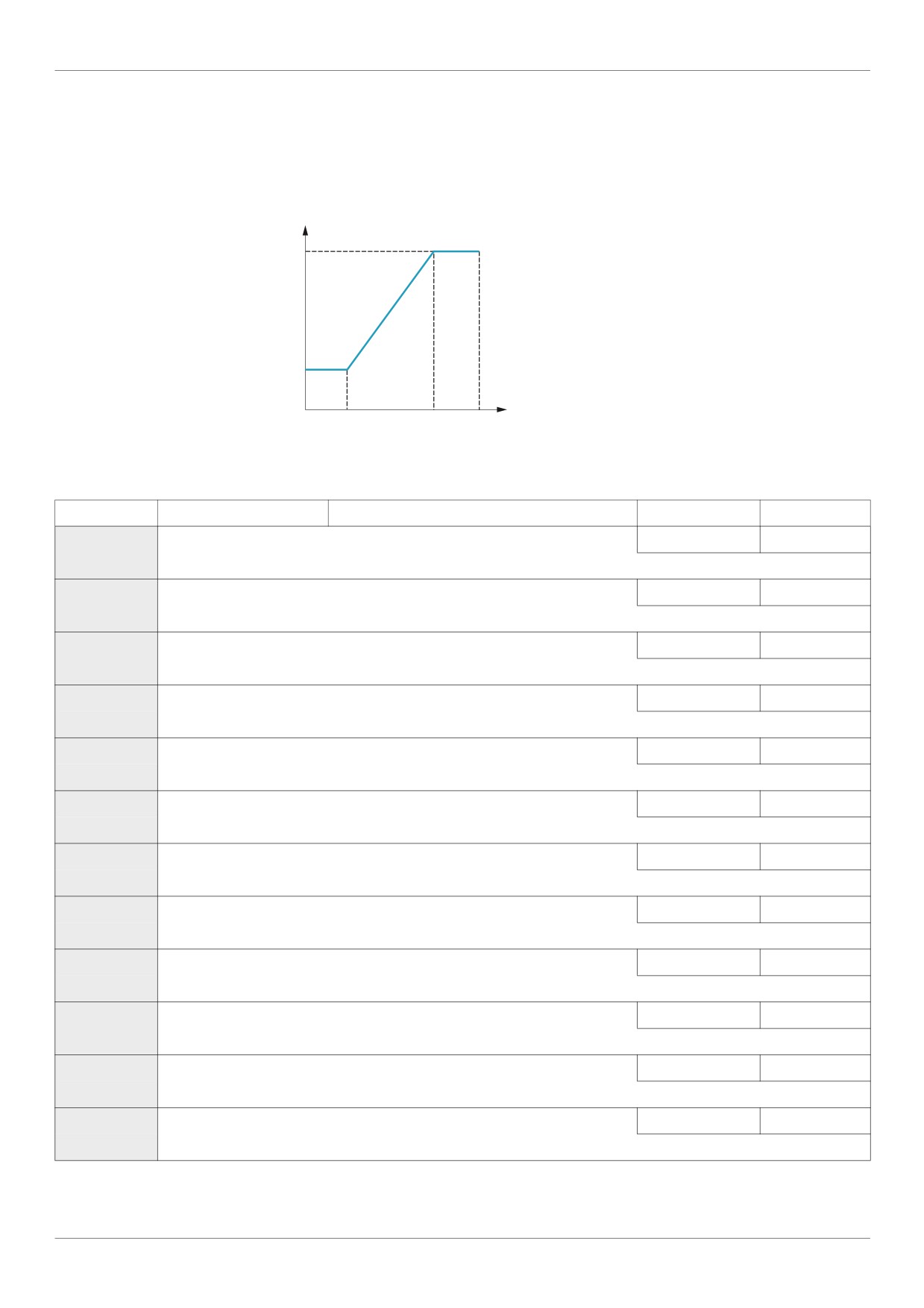
I/O Control Parameters
Analog Input Adjustments
Analog Input Speed Reference and Output Frequency
Do not set the same frequency values for both output frequency levels 1 and 2. This will cause an Err1
detected fault.
When using a 4-20 mA signal, set speed reference level 1 value to 20% (4 ÷ 20 = 20%).
Output Frequency Hz
F204
F202
Speed Reference %
F201
F203 20 mA
or
10 V
A further refinement of the bias and slope of the analog input signals can be made with parameters F470 -
F473.
Code
Name / Description
Adjustment range
Factory setting
F201
[VIA ref point 1]
VIA speed reference level 1
0 to 100%
0%
F202
[VIA freq. point 1]
VIA output frequency level 1
0.0 to 200.0 Hz
0.0 Hz
F203
[VIA ref point 2]
VIA speed reference level 2
0 to 100%
100%
F204
[VIA freq. point 2]
VIA output frequency level 2
0.0 to 200.0 Hz
50.0 Hz
F160
[VIA rel thresh. logic] Threshold logic for relay link to VIA
0 to 100%
0%
F161
[VIA threshold hyst.] Hysteresis threshold for logic relay link to VIA
0 to 20%
3%
F210
[VIB ref. point 1]
VIB speed reference level 1
0 to 100%
0%
F211
[VIB freq. point 1]
VIB output frequency level 1
0.0 to 200.0 Hz
0.0 Hz
F212
[VIB ref. point 2]
VIB speed reference level 2
0 to 100%
100%
F213
[VIB freq. point 2]
VIB output frequency level 2
0.0 to 200.0 Hz
50.0 Hz
F162
[VIB rel thresh. logic] Threshold logic for relay link to VIB
0 to 100%
0%
F163
[VIB threshold hyst.] Hysteresis threshold for logic relay link to VIB
0 to 20%
3%
116
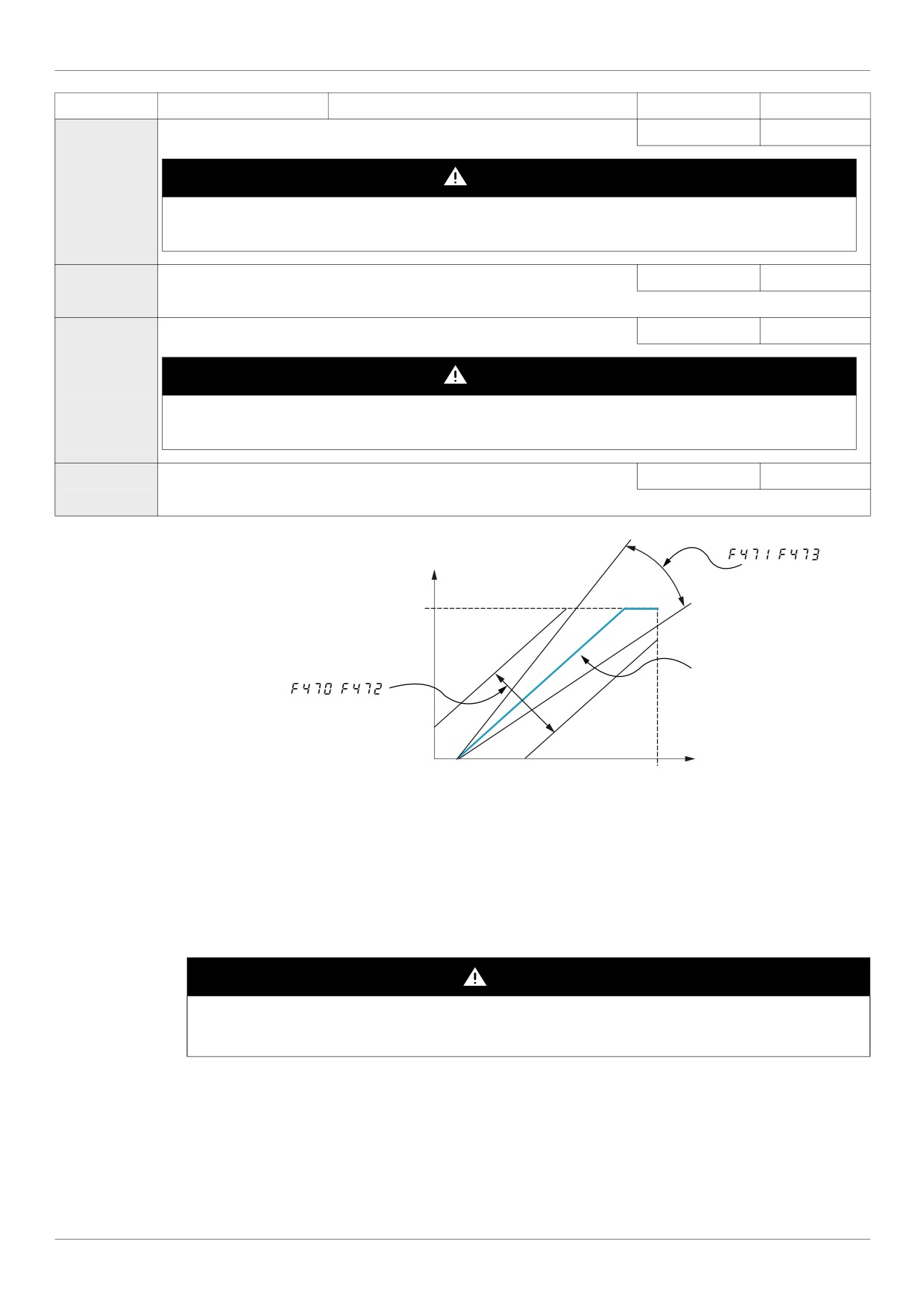
I/O Control Parameters
Code
Name / Description
Adjustment range
Factory setting
F470
[VIA bias]
VIA analog input bias
0 to 255
128
DANGER
UNINTENDED EQUIPMENT OPERATION
If the input bias level is set too high, the drive will start the motor without a signal present at VIA or VIB.
Failure to follow these instructions will result in death or serious injury.
F471
[VIA gain]
VIA analog input gain
0 to 255
148
F472
[VIB bias]
VIB analog input bias
0 to 255
128
DANGER
UNINTENDED EQUIPMENT OPERATION
If the input bias level is set too high, the drive will start the motor without a signal present at VIA or VIB.
Failure to follow these instructions will result in death or serious injury.
F473
[VIB gain]
VIB analog input gain
0 to 255
148
Large
,
Output frequency
Hz
Maximum frequency
Smaller
Large
Default Setting
,
Smaller
0
%
0%
100%
0 V
10 Vdc
0(4) mA
20 mAdc
Speed Reference Signal (VIA, VIB Input Value)
Parameters [VIA bias] (F470) and [VIB bias] (F472) are factory set so that a minimal signal needs to be
applied to VIA or VIB before the drive starts the motor.
To increase the signal level required to start the motor, decrease the input bias level.
To reduce the signal level required to start the motor, increase the input bias level.
DANGER
UNINTENDED EQUIPMENT OPERATION
If the input bias level is set too high, the drive will start the motor without a signal present at VIA or VIB.
Failure to follow these instructions will result in death or serious injury.
Parameters [VIA gain] (F471) and [VIB gain] (F473) are factory set so that the drive output reaches rated
voltage and frequency just before the signal to VIA or VIB reaches its maximum level.
To decrease the signal level required before the drive output reaches rated voltage and frequency, increase
the input gain level.
To increase the signal level required before the drive output reaches rated voltage and frequency, decrease
the input gain level.
Note: If the input gain level is set too low, the drive output may never reach rated voltage and frequency.
117
I/O Control Parameters
Code
Name / Description
Factory setting
F200
[Auto/man speed ref] Auto/Manual Speed Reference Switching
0
0
[Enable]
1
[Disable]
Switching between two speed reference sources by means of a logic input is enabled if parameter F200 is set to 0.
To use this function, you need to assign a logic input to function 38, Auto/Man speed ref.
When the assigned logic input is off, the drive will follow the speed reference source defined by parameter [Frequency mode sel]
(FMOd) (see page 87).
When the assigned logic input is on, the drive will follow the speed reference source defined by parameter [Remote spd ref 2]
(F207) (see page 88).
When parameter F200 is set to 1, the drive will follow the FMOd speed reference source when it is operating above 1 Hz.
Below 1 Hz, it will follow the F207 speed reference source.
FMSL
[AO funct. selection] Analog Output Function Selection
0
Value
Function
Maximum Signal
0
[Motor frequency]: Output frequency
[Max frequency] (FH)
1
[Motor current]: Output current
150 % of [Motor current]
2
[Speed ref]: Speed reference
[Max frequency] (FH)
3
[DC bus U]: DC bus voltage
150 % of [DC bus U]
4
[Motor U]: Output motor voltage
150 % of [Motor U]
5
[Input power]: Input power
185 % of [Input power]
6
[Output power]: Output power
185 % of [Output power]
7
[motor torque]: Estimated motor torque
250 % of rated motor torque
8
[Torque I]: Motor torque current
Current at 250 % of rated motor torque
9
[Motor thermal]: Motor thermal state
100 % of motor’s rating
10
[Drive thermal]: drive thermal state
100 %
11
[Do not use]: DO NOT USE
-
[Internal reference]: Internal speed
12
[Max frequency] (FH)
reference (after PID)
13
[VIA]: VIA input value
Maximum input value
14
[VIB]: VIB input value
Maximum input value
[Fixed 100%]: Fixed output - 100% signal
15
-
(Selection 1 - output current)
[Fixed 50%]: Fixed output - 50% signal
16
-
(Selection 1 - output current)
[Fixed 100%]: Fixed output - 100% signal
17
(Selections 0, 2, 3, 4, 5, 6, 7,
-
8, 9,10, 12, 13, 14, 18)
18
[Com data]: Serial communication data
FA51 = 1000
19
[Do not use]: DO NOT USE
-
FM
[AO scaling]
Analog Output Scaling
-
Parameter FM is used to match the FM terminal output signal with the input requirements of the attached panel meter by adjust-
ing the slope and bias of the analog output signal. Before adjusting FM, set [AO funct. selection] (FMSL) to either 15 or 17.
As you adjust the value of FM, monitor the display on the attached panel meter. When the meter display reaches 100%, press
the ENT key on the drive embedded display terminal. The drive will flash between FM and the adjusted value, indicating that the
adjustment has been saved.
118
I/O Control Parameters
Factory set-
Code
Name / Description
Adjustment range
ting
F691
[AO slope]
Analog Output Slope
-
1
0
[Negative slope]
1
[Positive slope]
F692
[Analog output bias]
0 to 100%
0%
Refer to the diagram below for examples of adjusting parameters [AO scaling] (FM), [AO slope] (F691), and F692.
= ,
=
= ,
=
(mA)
(mA)
20
20
4
0
0
100%
0
100%
FMSL signal value
FMSL signal value
= ,
=
= ,
=
(mA)
(mA)
20
20
:Large Gain
:Small Gain
4
0
0
100%
0
100%
FMSL signal value
FMSL signal value
F694
[Freq. for AO = 0V]
Low frequency when analog output equal 0 V
0 Hz to [Max frequency]
0 Hz
(FH)
Refer to the diagram below for adjusting parameters F694, and [Freq. for AO = 10V] (F695).
10 V
10 V
0 V
0 V
F694
F695
F695
F694
Speed reference
Speed reference
Motor frequency
Motor frequency
Internal reference (after PID)
Internal reference (after PID)
F695
[Freq. for AO = 10V]
High frequency when analog output equal 10 V
0 Hz to [Max frequency]
0 Hz
(FH)
Refer to the diagram above for adjusting parameters [Freq. for AO = 0V] (F694), and F695.
F130
[RY Relay Function 1] RYA-RYC Relay Function
0 to 69, 254, 255
4
If [Driving Scroll] (F324) page 160 is set to [yes] (1) the setting is replaced by [disable oil injection in high speed positive logic] (70)
For a complete description of the various functions assignable to the RYA-RYC relay, see page 108.
The RYA-RYC relay can have a secondary assignment with programmed selection logic. See parameters
[RY Relay Function 2] (F137) and [RY logic select.] (F139) on page 124 for more detail.
F146
[RY delay]
Delay for RYA-RYC Relay
0.0 to 60.0 s
0.0 s
This parameter introduce a delay on RYA-RYC output signal relay.
119