Altivar 212 Variable speed drives for synchronous and asynchronous motors. Programming Manual (2014) - page 1
Altivar 212
Variable speed drives
for synchronous and asynchronous motors
Programming Manual
11/2014
The information provided in this documentation contains general descriptions and/or technical characteristics
of the performance of the products contained herein. This documentation is not intended as a substitute for
and is not to be used for determining suitability or reliability of these products for specific user applications. It
is the duty of any such user or integrator to perform the appropriate and complete risk analysis, evaluation and
testing of the products with respect to the relevant specific application or use thereof. Neither Schneider
Electric nor any of its affiliates or subsidiaries shall be responsible or liable for misuse of the information
contained herein. If you have any suggestions for improvements or amendments or have found errors in this
publication, please notify us.
No part of this document may be reproduced in any form or by any means, electronic or mechanical, including
photocopying, without express written permission of Schneider Electric.
All pertinent state, regional, and local safety regulations must be observed when installing and using this
product. For reasons of safety and to help ensure compliance with documented system data, only the
manufacturer should perform repairs to components.
When devices are used for applications with technical safety requirements, the relevant instructions must be
followed.
Failure to use Schneider Electric software or approved software with our hardware products may result in
injury, harm, or improper operating results.
Failure to observe this information can result in injury or equipment damage.
2
Table of Contents
Table of Contents
Safety Information
7
About the Book
8
General Overview
11
Chapter 1
Setup
13
Steps for setting-up the drive
14
Chapter 2
Overview
15
Factory configuration
16
Preliminary recommendations
17
Embedded display terminal
18
Monitoring Mode
20
Run Mode
23
Programming Mode
23
Menu Navigation
24
Submenus
34
Graphic display option
35
Finding a parameter in this document
37
Detected fault screens
37
Pre-alarms screens
38
Modbus communication status
38
SoMove software
39
Structure of the parameter tables
40
Parameters that cannot be changed while the drive is running
41
Common control schemes
42
Drive Operation
49
Programming
57
Chapter 3
Quick Menu
59
Quick menu
60
Chapter 4
Programming Parameters
65
Parameter Reset
66
Macro Programming (AU4)
67
Parameter Lock
68
Display of Submenu AUF (F738)
68
Chapter 5
Motor Control Parameters
69
Motor Control Mode
70
Other Motor Control Mode Parameters
72
Motor Tuning
74
Auto-tuning
75
Expert parameters
77
Supply Voltage Correction and Motor Voltage Limitation
78
3
Table of Contents
Motor 2 Control Parameters
79
Permanent Magnet Motor Control Law ([PM Control] (PM))
81
Chapter 6
Drive Control Parameters
87
Chapter 7
Application Parameters
91
Application parameters
92
Skip Frequencies
97
DC Injection Braking Parameters
98
Chapter 8
I/O Control Parameters
99
Logic Inputs Functions
100
Logic Input Function Compatibility
107
Relay Output Functions
108
Analog Input Functions
114
Analog Output Functions
115
Analog Input Adjustments
116
Active Logic Function
122
Preset Speeds
123
+/- Speed Control Parameters
124
Damper control
127
Chapter 9
Display Parameters
129
Display parameters
130
Chapter 10
Detected Fault Management Parameters
133
Time delay
136
Catch On The Fly (F301)
137
Overtorque Detection
143
Nuisance Overvoltage And Input Phase Detected Fault Avoidance
144
Motor Overload Characteristics
145
Chapter 11
Serial Communication Parameters
147
Network communication between the ATV212 drive and a master controller
148
Data structure parameters
150
Chapter 12
Start/Stop Control By Speed Reference Level
153
Overview
154
Chapter 13
Droop Control
155
Droop control principle
156
Chapter 14
Functions for Scroll
157
Driving Scroll (F324)
160
Pre-start Scroll (F325)
170
Std Oiling Cycle (F330)
172
Low Speed Oiling (F334)
173
Scroll Protection (F338)
174
Discharge gas (F349)
175
Crankcase heating (F355)
176
Diagnostics and troubleshooting
177
Chapter 15
Diagnostics and troubleshooting
179
Detected fault conditions
180
Alarm Conditions
184
Pre-alarm Conditions
186
Clearing the detected fault
187
4
Table of Contents
Annex
189
Chapter 16
Migration
191
Migration ATV21 - ATV212
192
Chapter 17
Parameters Reset Tables
193
Parameter values that do not vary by reset type
194
Parameter values that vary according to reset type
198
Parameter values that vary According to drive rating, but not reset type
199
Parameter values that vary According to drive rating and reset type
200
Parameter values that do not change if reset
201
Chapter 18
User Settings Tables
203
5
Table of Contents
6
Safety Information
Safety Information
§
Important Information
NOTICE
Please read these instructions carefully and examine the equipment in order to familiarize yourself with the
device before installing, operating or carrying out any maintenance work on it.
The following special messages that you will come across in this document or on the device are designed to
warn you about potential risks or draw your attention to information that will clarify or simplify a procedure.
The addition of this symbol to a Danger or Warning safety label indicates that an electrical hazard
exists, which will result in personal injury if the instructions are not followed.
This is the safety alert symbol. It is used to alert you to potential personal injury hazards. Obey all
safety messages that follow this symbol to avoid possible injury or death.
DANGER
DANGER indicates an imminently hazardous situation, which, if not avoided, will result in death or serious
injury.
WARNING
WARNING indicates a potentially hazardous situation, which, if not avoided, can result in death, serious injury,
or equipment damage.
CAUTION
CAUTION indicates a potentially hazardous situation, which, if not avoided, can result in injury or equipment
damage.
NOTICE
NOTICE, used without the safety alert symbol, indicates a potentially hazardous situation which, if not avoided,
can result in equipment damage.
PLEASE NOTE
The word "drive" as used in this manual refers to the controller portion of the adjustable speed drive as defined
by NEC.
Electrical equipment should be installed, operated, serviced, and maintained only by qualified personnel. No
responsibility is assumed by Schneider Electric for any consequences arising out of the use of this product.
7
About the Book
About the Book
At a Glance
Document scope
The purpose of this document is to:
• help you to set-up the drive,
• show you how to program the drive,
• show you the different menus, modes and parameters,
• help you in maintenance and diagnostics.
Validity note
This documentation is valid for the Altivar 212 drive.
Related documents
Title of Documentation
Reference Number
ATV212 Quick Start
S1A53825
ATV212 Installation manual
S1A53832
ATV212 Modbus manual
S1A53844
ATV212 BACnet manual
S1A53845
ATV212 Metasys N2 manual
S1A53846
ATV212 Apogée FLN P1 manual
S1A53847
ATV212 LonWorks manual
S1A53848
Multi-Loader manual
BBV48778
SoMove Mobile manual
S1A51444
ATV212 other option manuals: see www.schneider-electric.com
You can download the latest versions of these technical publications and other technical information from our
website at www.schneider-electric.com.
Standards and Terminology
The technical terms, terminology, and the corresponding descriptions in this manual normally use the terms
or definitions in the relevant standards.
In the area of drive systems this includes, but is not limited to, terms such as error, error message, failure,
fault, fault reset, protection, safe state, safety function, warning, warning message, and so on.
Among others, these standards include:
• IEC 61800 series: Adjustable speed electrical power drive systems
• IEC 61508 Ed.2 series: Functional safety of electrical/electronic/programmable electronic safety-related
• EN 954-1 Safety of machinery - Safety related parts of control systems
• EN ISO 13849-1 & 2 Safety of machinery - Safety related parts of control systems.
• IEC 61158 series: Industrial communication networks - Fieldbus specifications
• IEC 61784 series: Industrial communication networks - Profiles
• IEC 60204-1: Safety of machinery - Electrical equipment of machines - Part 1: General requirements
8
About the Book
Product related information
DANGER
HAZARD OF ELECTRIC SHOCK, EXPLOSION OR ARC FLASH
• Only appropriately trained persons who are familiar with and understand the contents of this manual and all
other pertinent product documentation and who have received safety training to recognize and avoid
hazards involved are authorized to work on and with this drive system. Installation, adjustment, repair and
maintenance must be performed by qualified personnel.
• The system integrator is responsible for compliance with all local and national electrical code requirements
as well as all other applicable regulations with respect to grounding of all equipment.
• Many components of the product, including the printed circuit boards, operate with mains voltage. Do not
touch. Use only electrically insulated tools.
• Do not touch unshielded components or terminals with voltage present.
• Motors can generate voltage when the shaft is rotated. Prior to performing any type of work on the drive
system, block the motor shaft to prevent rotation.
• AC voltage can couple voltage to unused conductors in the motor cable. Insulate both ends of unused
conductors of the motor cable.
• Do not short across the DC bus terminals or the DC bus capacitors or the braking resistor terminals.
• Before performing work on the drive system:
- Disconnect all power, including external control power that may be present.
- Place a "Do Not Turn On" label on all power switches.
- Lock all power switches in the open position.
- Wait 15 minutes to allow the DC bus capacitors to discharge. The DC bus LED is not an indicator of the
absence of DC bus voltage that can exceed 800 Vdc.
- Measure the voltage on the DC bus between the DC bus terminals (PA/+ and PC/-) using a properly rated
voltmeter to verify that the voltage is < 42 Vdc.
- If the DC bus capacitors do not discharge properly, contact your local Schneider Electric representative.
• Install and close all covers before applying voltage.
Failure to follow these instructions will result in death or serious injury.
DANGER
UNINTENDED EQUIPMENT OPERATION
• Prevent accidental grounding of logic inputs configured for sink logic. Accidental grounding can result in
unintended activation of drive functions.
• Protect the signal conductors against damage that could result in unintentional conductor grounding.
Failure to follow these instructions will result in death or serious injury.
WARNING
LOSS OF CONTROL
• The designer of any control scheme must consider the potential failure modes of control paths and, for
critical control functions, provide a means to achieve a safe state during and after a path failure. Examples
of critical control functions are emergency stop, overtravel stop, power outage, and restart.
• Separate or redundant control paths must be provided for critical control functions.
• System control paths may include communication links. Consideration must be given to the implications of
unanticipated transmission delays or failures of the link.
• Observe all accident prevention regulations and local safety guidelines (1).
• Each implementation of the product must be individually and thoroughly tested for proper operation before being
placed into service.
Failure to follow these instructions can result in death, serious injury, or equipment damage.
(1) For USA: Additional information, refer to NEMA ICS 1.1 (latest edition), “Safety Guidelines for the Application, Installation, and Maintenance
of Solid State Control” and to NEMA ICS 7.1 (latest edition), “Safety Standards for Construction and Guide for Selection, Installation and
Operation of Adjustable Speed Drive Systems.”
9
About the Book
10
General Overview
General Overview
I
What's in this Part?
This part contains the following chapters:
Chapter
Chapter Name
Page
1
Setup
13
2
Overview
15
11
General Overview
12
Setup
Setup
1
What's in this Chapter?
This chapter contains the following topics:
Topic
Page
Steps for setting-up the drive
14
13
Setup
Steps for setting-up the drive
INSTALLATION
1. Please, refer to the installation manual..
PROGRAMMING
2. Apply input power to the drive, but do not give a
run command.
3. Configure
v the nominal frequency of the motor
[Parameter reset] (tYP) = [50 Hz reset] (1)
if this is not 50Hz,
v the motor parameters, page 70, only if the
Tips:
factory configuration of the drive is not
suitable,
Before beginning programming, complete the customer
setting tables, page 203.
v the application functions in the Drive Control
Perform an auto-tuning operation to optimize performance,
Parameters section, page 87 and the I/O
page 75.
Control Parameters section, page 99, only if
If you get lost, return to the factory settings, page 66.
the factory configuration of the drive is not
suitable.
4. Adjust the application parameters
v
[Acceleration time 1] (ACC), page 93
and [Deceleration time 1] (dEC),
page 93.
v
[Low limit frequency] (LL), page 92
and [Upper limit freq] (UL), page 92.
v
[Motor thermal prot.] (tHr), page 74.
5. Start the drive
14
Overview
Overview
2
What's in this Chapter?
This chapter contains the following topics:
Topic
Page
Factory configuration
16
Preliminary recommendations
17
Embedded display terminal
18
Monitoring Mode
20
Run Mode
23
Programming Mode
23
Menu Navigation
24
Submenus
34
Graphic display option
35
Finding a parameter in this document
37
Detected fault screens
37
Pre-alarms screens
38
Modbus communication status
38
SoMove software
39
Structure of the parameter tables
40
Parameters that cannot be changed while the drive is running
41
Common control schemes
42
Drive Operation
49
15
Overview
Factory configuration
Drive factory settings
The Altivar 212 is factory-set for the most common operating conditions:
[Mot cont. mode sel.] (Pt): [Variable torque] (Pt = 1). See page 71.
[Upper limit freq] (UL) = 50.0 Hz. See page 92.
[Low limit frequency] (LL) = 0.0 Hz. See page 92.
[Switch. freq. level] (F300): depending on drive rating (see page 95)
[Auto ramp] (AU1) = [Enable] (AU1 =1). See page 95.
Parameter which depends on Macro Programming [Auto set function] (AU4) = 0 (see page 67):
Command reference: logic inputs ([Command mode sel] (CMOd) = 0). See page 87.
Speed reference: analog input VIA = 0-10 V or 0-20 mA ([Frequency mode sel] (FMOd) = 1, (F201)= 0).
See [Frequency mode sel] (FMOd) page 87 and Analog Input Speed Reference page 116.
F: run forward (F111= 2). See [LI F selection] page 100.
R: preset speed 1 (F112= 6). See [LI R selection] page 100.
RES: clear detected fault (F113= 10). See [LI RES selection] page 100.
Drive ready for operation (F110= 1). See [Logic Funct 2 active] page 122.
If the above values are compatible with the application, the drive can be used without changing the settings.
16
Overview
Preliminary recommendations
NOTICE
INCOMPATIBLE LINE VOLTAGE
Before turning on and configuring the drive, ensure that the line voltage is compatible with the supply voltage
range shown on the drive nameplate. The drive may be damaged if the line voltage is not compatible.
Failure to follow these instructions can result in equipment damage.
Power switching via line contactor
NOTICE
RISK OF DAMAGE TO THE DRIVE
Avoid operating the contactor frequently.
Power cycling must be MORE than 60 seconds.
Failure to follow these instructions can result in equipment damage.
User adjustment and extension of functions
The display unit and buttons can be used to modify the settings and to extend the functions described in the
following pages.
Return to factory settings is made easy by the [Parameter reset] (tYP) (see page 66).
DANGER
UNINTENDED EQUIPMENT OPERATION
Check that changes made to the settings during operation do not present any danger.
We recommend stopping the drive before making any changes.
Failure to follow these instructions will result in death or serious injury.
Test on a low power motor or without a motor
In factory settings mode, [Output phase loss] (F605) (page 140) is active F605 = 3. To check the drive
in a test or maintenance environment without having to switch to a motor with the same rating as the drive
(particularly useful in the case of high power drives), set F605 to 0.
Set [Mot cont. mode sel.] (Pt) = [Constant V/Hz] (0) (see page 71).
NOTICE
UNINTENDED EQUIPMENT OPERATION
Motor thermal protection will not be provided by the drive if the motor 's nominal current is 20% lower than that
of the drive. Find an alternative source of thermal protection.
Failure to follow these instructions can result in equipment damage.
Using motors in parallel
Set [Mot cont. mode sel.] (Pt) = [Constant V/Hz] (0) (see page 71).
NOTICE
RISK OF DAMAGE TO THE MOTOR
Motor thermal protection is no longer provided by the drive. Provide an alternative means of thermal protection.
Failure to follow these instructions can result in equipment damage.
Using in single phase supply
Set [Input phase loss] (F608) to Disabled 0 (see page 138).
NOTICE
RISK OF DAMAGE TO THE DRIVE
Using ATV212 in single phase supply is only allowed in training mode with motor and without load.
Failure to follow these instructions can result in equipment damage.
17
Overview
Embedded display terminal
This section describes the features of the integrated display terminal.
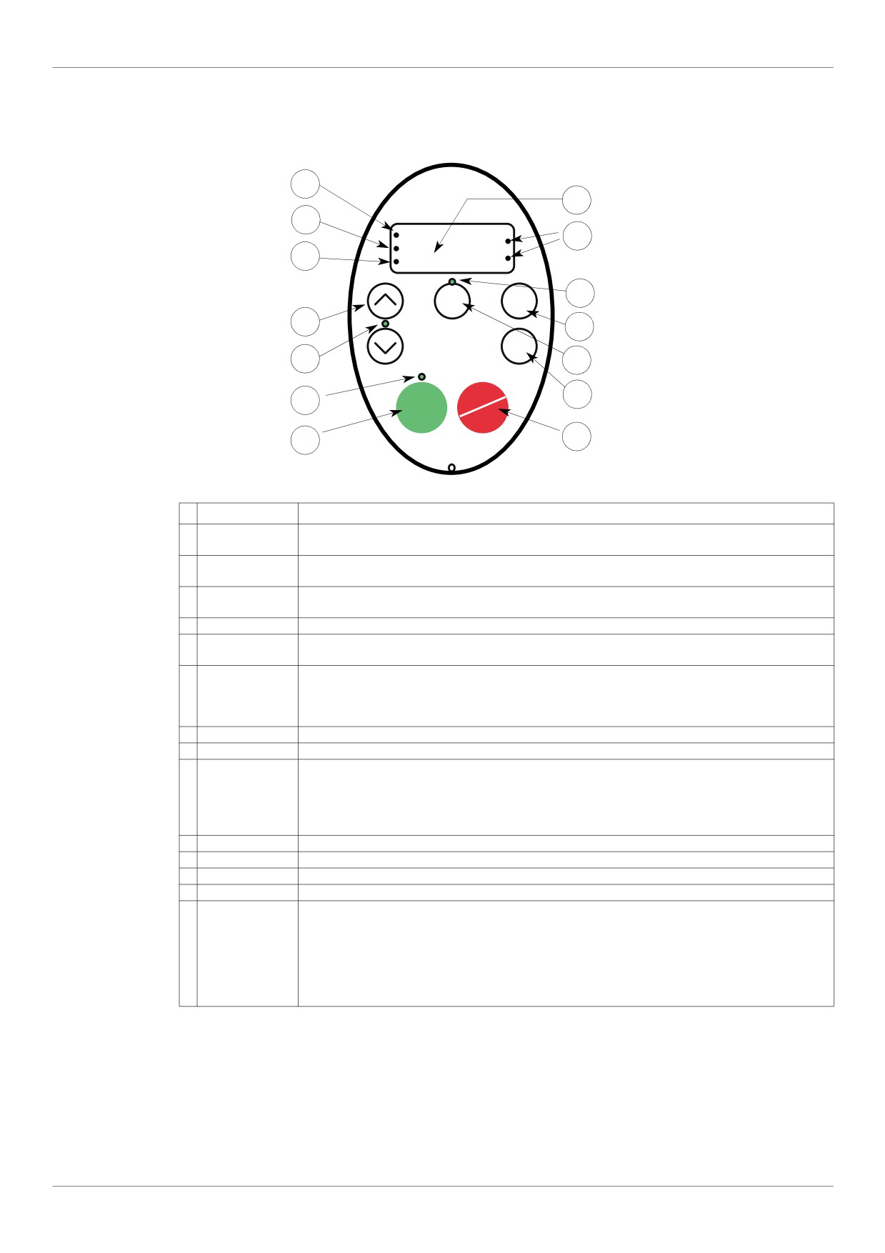
Embedded display terminal features
1
4
2
RUN
5
%
PRG
3
Hz
MON
Loc
8
MODE
Rem
6
9
ENT
7
10
12
STOP
11
RUN
RESET
13
14
LED/Key
Characteristics
1
Display RUN LED
Illuminates when a run command is applied to the drive.
Flashes when there is a speed reference present with a Run command.
2
Display PRG LED
Illuminates when Programming mode is active.
Flashes in AUF, GrU modes
3
Display MON LED
Illuminates when Monitoring mode is active.
Flashes in detected fault history display mode
4
Display unit
4 digits, 7 segments
5
Display unit LED
The % LED illuminates when a displayed numeric value is a percentage.
The Hz LED illuminates when a displayed numeric value is in hertz.
6
UP/DOWN keys
Depending on the mode, you can use the arrows to:
Navigate between the menus
Change a value
Change the speed reference when the UP/DOWN LED (7) is illuminated
7
UP/DOWN LED
Illuminates when the navigation arrows are controlling the speed reference
8
Loc/Rem LED
Illuminates when Local mode is selected
9
MODE
Press to select the embedded display terminal mode.
Run mode (default on power-up)
Programming mode
Monitoring mode
Can also be used to go back to the previous menu.
10
Loc/Rem
Switches between Local and Remote modes
11
ENT
Press to display a parameter’s value or to save a changed value.
12
RUN LED
Illuminates when the Run key is enabled
13
RUN
Pressing this key when the RUN LED is illuminated starts the drive.
14
STOP
Stop/reset key.
In Local mode, pressing the STOP key causes the drive to stop based on the setting of parameter [Loc.
mot stop mode] (F721).
In Remote mode, pressing the STOP key causes the drive to stop based on the setting of parameter
[Ext. fault stop Mode] (F603). The display will indicate a flashing “E”.
If [HMI reset button] (F735) is set to 0, pressing the stop key twice will reset the drive, if the detected
fault condition has been cleared.
An optional graphic display option (VW3A1101) is also available.
18
Overview
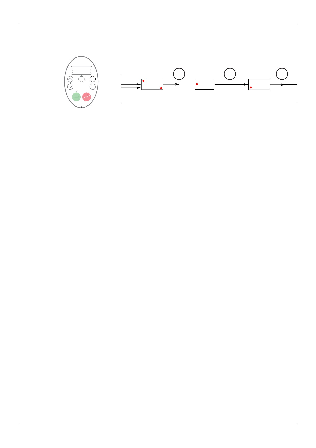
Embedded display terminal modes
The Altivar 212 embedded display terminal has three modes of operation: Monitoring, Run and Programming.
The drive powers up in the Run mode. To select a different mode, use the MODE key as illustrated below.
ATV212
RUN
%
drive
PRG
Run
Programming
Monitoring
MON
Hz
Power Up
mode
MODE
mode
MODE
mode
MODE
Loc
MODE
Rem
RUN
0.0
PRG
AUF
Fr-F
ENT
MON
Hz
STOP
RUN
RESET
The red LED in left side of the display indicates the current mode selected, RUN for Run mode, PRG for
Programming mode and MON for Monitoring mode.
19
Overview
Monitoring Mode
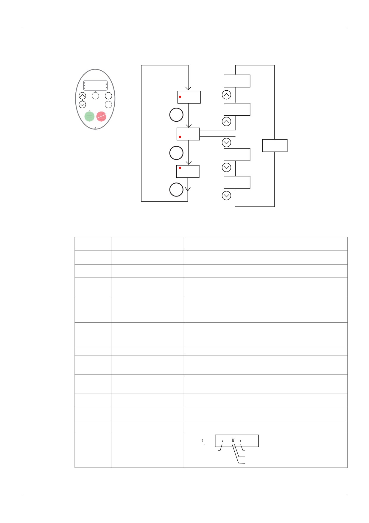
The Monitoring mode displays drive operational data in real time. To access the Monitoring mode, press the
MODE key until the MON LED is illuminated. Then use the UP and DOWN keys to view up to 30 different types
of data.
C80
RUN
%
PRG
MON
Hz
Loc
MODE
Rem
PRG
AUF
ENT
F60.
0
STOP
MODE
RUN
RESET
Fr-F
MON
25 other
parameters
MODE
t0.
10
RUN
0.0
n---
MODE
Monitoring Mode Displays
Display
Display on graphic terminal
Description
example
Fr-F
[Direction]
Fr-F = [Forward]
Fr-r = [Reverse]
F60.0
[Speed reference]
Command frequency to drive, displayed either as Hz or in custom unit set
by parameter [Customized freq val] (F702)
C 80
[Motor current]
The average of the 3 phases of motor current displayed either as amperes
or as a percentage of the drive's nameplate-rated output current. Select %
or A with parameter [Unit value selection] (F701).
Y 100
[Line voltage]
The average of the 3 phases of line to line input voltages displayed either
in volts or as a percentage of the drive's rated input voltage (200 V for
208/240 V models - 400 V for 480 V models). Select % or volts with param-
eter [Unit value selection] (F701).
P 100
[Motor voltage]
The average of the 3 phases of line to line output voltages displayed either
in volts or as a percentage of the drive's rated output voltage (200 V for
208/240 V models - 400 V for 480 V models). Select % or volts with param-
eter [Unit value selection] (F701).
q 60
[Motor torque %]
Estimated motor torque as a percentage of the motor's rated torque
c 90
[Torque current]
The average of the 3 phases of torque-producing motor current displayed
either as amperes or as a percentage of the motor's rated torque-producing
current. Select % or A with parameter [Unit value selection] (F701).
L 70
[Drive load %]
The motor current as a percentage of the drive's rated output current, which
may be reduced from the drive’s nameplate current rating by adjustments
in switching frequency.
h 80
[Input power KW]
drive input power displayed in accordance with parameter [Power cons.
unit] (F749).
H 75
[Output power KW]
drive output power displayed in accordance with parameter [Power cons.
unit] (F749).
o60.0
[Motor frequency]
Motor operating frequency, displayed either as Hz or in custom unit set by
parameter [Customized freq val] (F702)
..11
[Logic input map]
ON:
The bar representing VIA is dis-
OFF:
played only if F109 = 1 or 2
VIA
F
R
RES
20
Overview
Display
Display on graphic terminal
Description
example
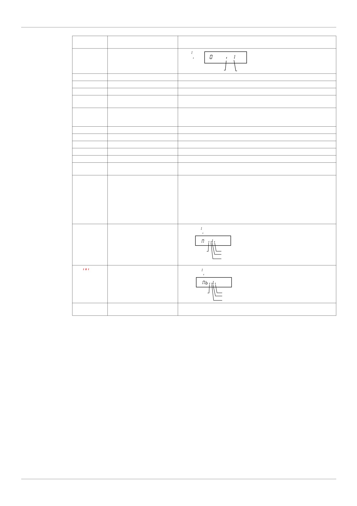
0.1
[Relay map]
ON:
OFF:
FL
RYA-RYC
u101
[CPU CTRL ver.]
CTRL version 101
uc01
[CPU MMI ver.]
MMI version 1.0
uE01
[Memory ver.]
Version of memory
d50.0
[PID feedback]
Level of PID feedback, displayed either as Hz or in custom unit set by pa-
rameter [Customized freq val] (F702)
b70.0
[PID computed ref.]
Speed reference command to drive as computed by the PID function, dis-
speed reference
played either as Hz or in custom unit set by parameter [Customized freq
val] (F702)
h85
[Total input power]
Accumulated input power consumed by the drive displayed in kWh
H75
[Total motor power]
Accumulated output power supplied by the drive displayed in kWh
A16.5
[Drive out. rat. cur. A]
Drive nameplate rated output current in amperes
1500
[Motor speed rpm]
Motor speed in rpm
N50
[Comm. counter 2]
Displays the counter numbers of communication through the network
n50
[Comm. counter 1]
Displays the counter numbers of communication only at normal state in ev-
ery communication through the network
nErr
[Past fault]
The most recent detected fault stored in the detected fault history. If the
Examples:
drive is in a detected fault state, this is not the active detected fault. A de-
- 1 blink Err5
tected fault is stored in the detected fault history after it is cleared by clear
- 2 blink Err5
detected fault action. Press ENT to review drive state at time of detected
- 3 blink CFI2
fault. See “Detected fault Display and History” on page 21 and “Diagnostics
- 4 blink nErr
and troubleshooting” on page 179 for more detail. There are 4 detected
faults recorded. The detected fault 4 is cleared when a new detected fault
appears.
N...1
[Drive service alarm]
ON:
OFF:
Cumulative
Cooling fan
Operation
Main Control board
DC Bus capacitor
Time
Mb
[Mdb com stat]
ON:
OFF:
OpenStyle Tx
RJ45 Rx
OpenStyle Rx
RJ45 Tx
t0.10
[Drive run time 100h]
Cumulative drive run time. 0.01 = 1 hour.
1.00 = 100 hours
Detected fault display and history
When the drive detected faults, the graphic terminal displays a code. To review data about drive operation at the
time of the detected fault, press the MODE key to enter the Monitoring mode. Then use the Up/Down keys to
scroll through the data listed in table page 20.
Up to five detected faults can be displayed on the graphic terminal in Monitoring mode: the present detected fault
(if the drive is in a detected fault state) and the previous four detected fault codes. To review drive operation data
recorded at the time of detected fault for a previous detected fault, press ENT when the code for the detected
fault is displayed. See table below for the available information.
When a detected fault is cleared or power is cycled to the drive, the present detected fault becomes Past
detected fault 1.
21
Overview
Detected fault History
Display
Display on graphic terminal
Description
n 2
[Comm. counter 1]
Number of times in succession that this particular detected fault has oc-
curred
o60.0
[Motor frequency]
Motor operating frequency, displayed either as Hz or in custom unit set by
parameter [Customized freq val] (F702)
Fr-F
[Direction]
Fr-F = [Forward]
Fr-r = [Reverse]
F60.0
[Speed reference]
Command frequency to drive, displayed either as Hz or in custom unit set
by parameter [Customized freq val] (F702)
C80
[Motor current]
The average of the 3 phases of motor current displayed either as A or as a
percentage of the drive's nameplate-rated output current. Select % or A
with parameter [Unit value selection] (F701).
Y100
[Line voltage]
The average of the 3 phases of line to line input voltages displayed either
in volts or as a percentage of the drive's rated input voltage (200 V for
208/240 V models - 400 V for 480V models). Select % or volts with param-
eter [Unit value selection] (F701).
P100
[Motor voltage]
The average of the 3 phases of line to line output voltages displayed either
in volts or as a percentage of the drive's rated output voltage (200 V for
208/240 V models - 400 V for 480 V models). Select % or volts with param-
eter [Unit value selection] (F701).
..11
[LOGIC INPUT MAP]
Logic input map
ON:
The bar representing VIA is
OFF:
displayed only if
VIA
F
F109 = 1 or 2
R
RES
0.1
[Relay map]
ON:
OFF:
FL
RYA-RYC
t0.10
[Drive run time 100h]
Cumulative drive run time. 0.01 = 1 hour. 1.00 = 100 hours
I/O Map
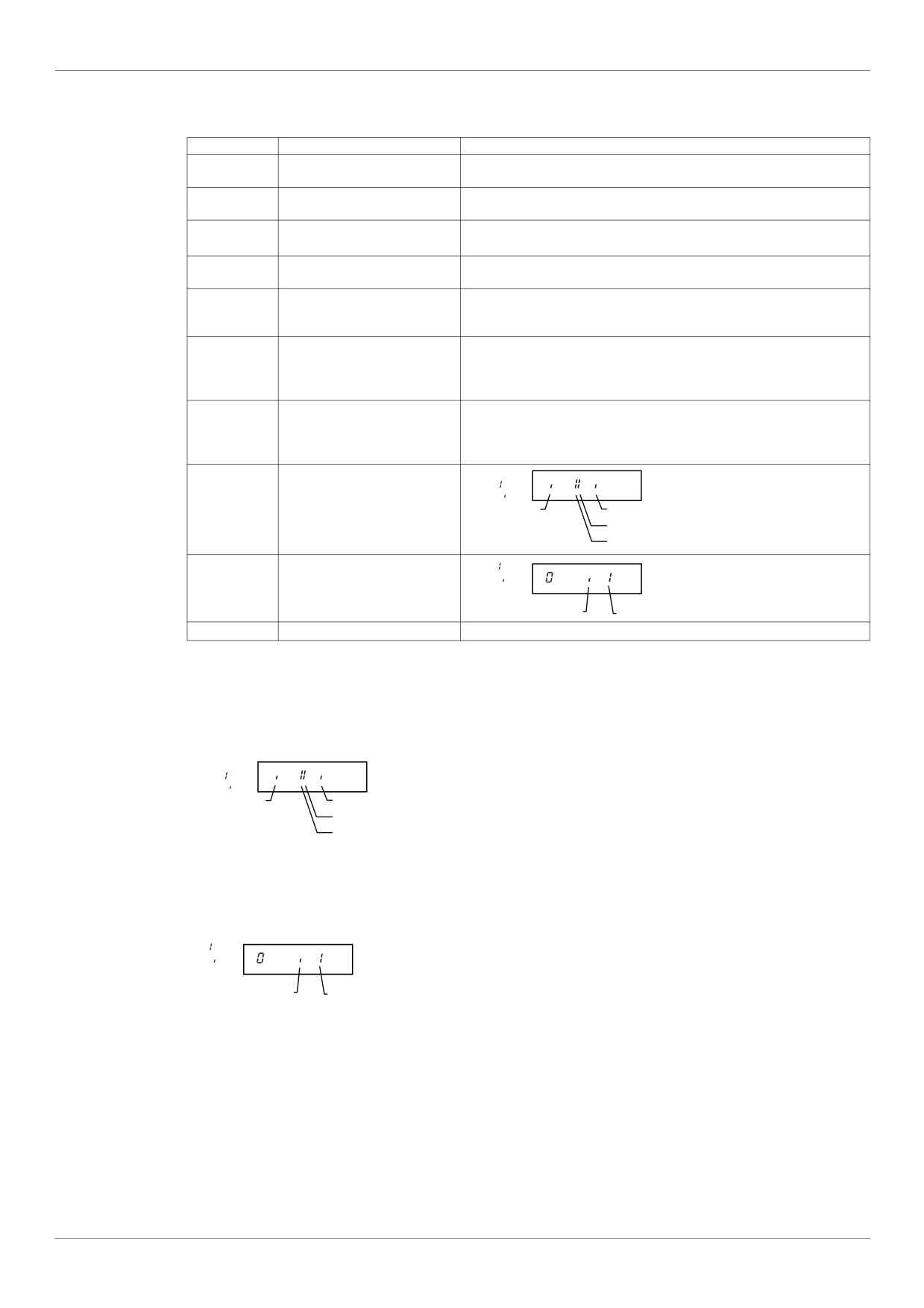
In both the monitoring mode and the detected fault history, it is possible to view the state of the logic inputs and
the relay outputs. See previous tables on pages 20 and 21.
Logic Input Map
ON:
OFF:
VIA
F
R
RES
The ON or OFF status of each logic input is displayed in bits. VIA is included in this display if parameter F109
is set to either 1 or 2.
Relay Output Map
ON:
OFF:
FL
RYA-RYC
The ON or OFF status of each relay output is displayed in bits.
22
Overview
Run Mode
To access the Run mode, press the MODE key until the drive operating frequency, a detected fault code, or a
pre-alarm code is displayed.
See Diagnostics and troubleshooting beginning on page 179 for the detected fault and pre-alarm codes.
Changing the Display in Run Mode
Motor operating frequency is the default value displayed on the graphic terminal in Run mode. This displayed
value can be changed by setting parameter [Displayed param.] (F710). See page 130 for a list of the display
choices.
The displayed value can be expressed as a percentage of the drive rating, or in amperes or volts, as appropriate
for the value displayed. The units can be changed by setting parameter [Unit value selection] (F701) (see
page 130).
In addition, the resolution of the speed reference and output frequency displays can be adjusted by setting
parameters [Loc. speed ref. step] (F707) and [Display ref. resol.] (F708) (see pages 87 and 130).
Programming Mode
Use this mode to program the drive.
To access the Programming mode, use the MODE key until the PRG indicator LED on the display is illuminated.
See Menu Navigation page 24.
23
Overview
Menu Navigation
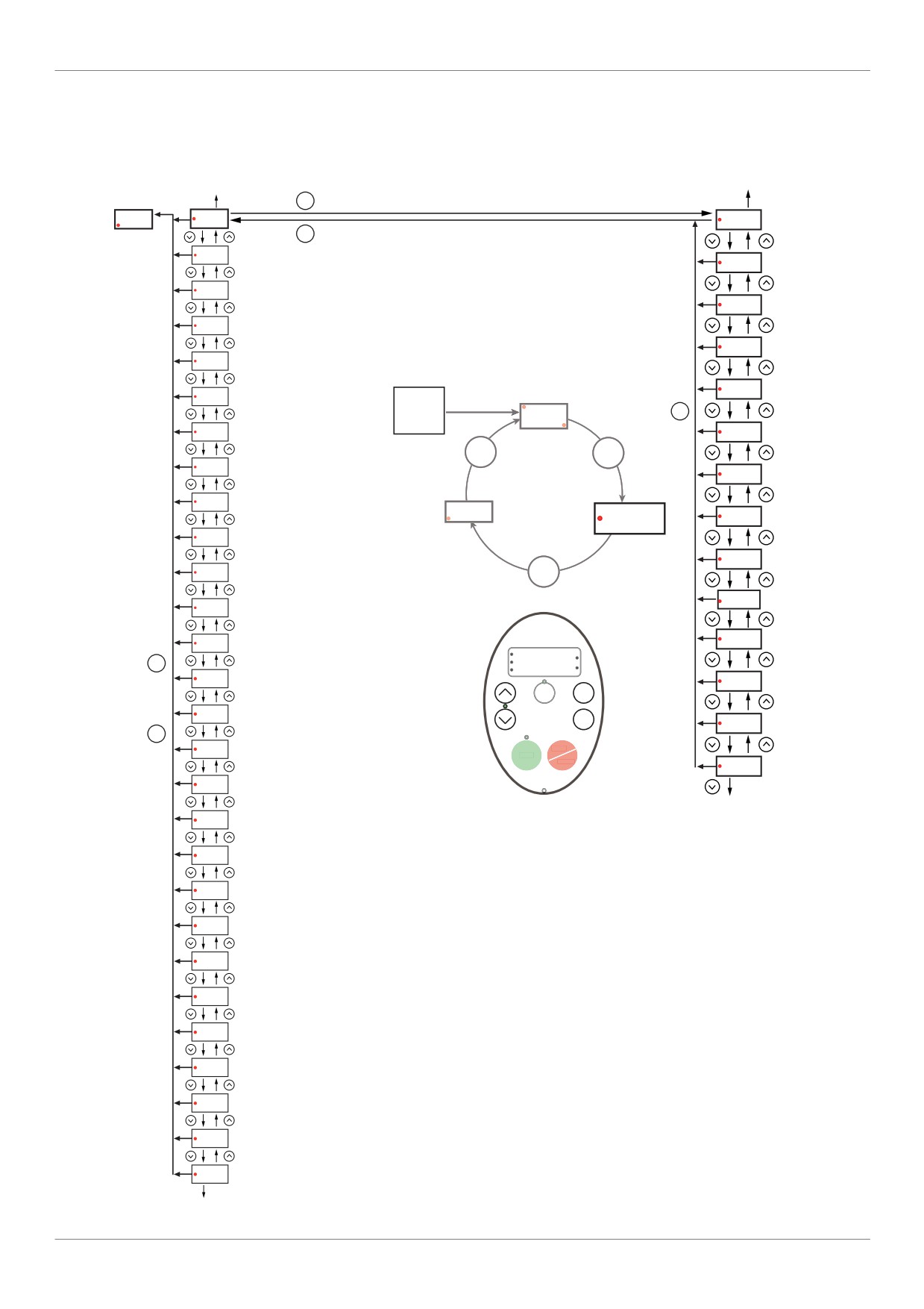
Menu navigation diagrams below illustrate how to navigate through the programming menus and submenus.
AUH [Quick menu] submenu
to AUH
to uLu
Programming
mode
SUBMENU [Quick menu]
ENT
Fr-F
AUF
AU1
[Auto ramp]
MODE
GrU
SUBMENU [ALL PARAM CHANGE]
ACC
[Acceleration time 1]
F---
SUBMENU [EXTENDED MENU]
dEC
[Deceleration time 1]
IO
SUBMENU [I/O MENU]
LL
[Low limit frequency]
COM
SUBMENU [COMMUNICATION MENU]
UL
[Upper limit freq]
SCr
SUBMENU [SCROLL MENU]
RUN
Power
MODE
UP
0.0
PM
SUBMENU [PM MOTOR MENU]
Hz
tHr
[Motor thermal prot.]
MODE
MODE
Sr7
[Preset speed 7]
FM
[AO scaling]
OLM
[Motor overload prot]
MON
Fr - F
PRG
Pt
[Mot cont. mode sel.]
AUF
tHr
[Motor thermal prot.]
uL
[Motor rated freq.]
ub
[Mot Voltage Boost]
MODE
[Motor rated voltage]
Pt
[Mot cont. mode sel.]
uLu
F415
[Motor rated current]
uLu
[Motor rated voltage]
RUN
MODE
PRG
%
MON
Hz
uL
[Motor rated freq.]
[Motor rated speed]
F417
Loc
MODE
Rem
LL
[Low limit frequency]
ENT
F601
[Motor Current Limit]
MODE
UL
[Upper limit freq]
STOP
RUN
RESET
F400
[Auto-tuning drive]
FH
[Max frequency]
to AUI
dEC
[Deceleration time 1]
ACC
[Acceleration time 1]
Fr
[Local mot. Direction]
tYP
[Parameter reset]
FM
[AO scaling]
FMSL
[AO funct. selection]
FMOd
[Frequency mode sel]
CMOd
[Command mode sel]
AU4
[Auto set function]
AU1
[Auto ramp]
AUH
SUBMENU [5 LAST PARAM CHANGE]
to AUF
24
Overview
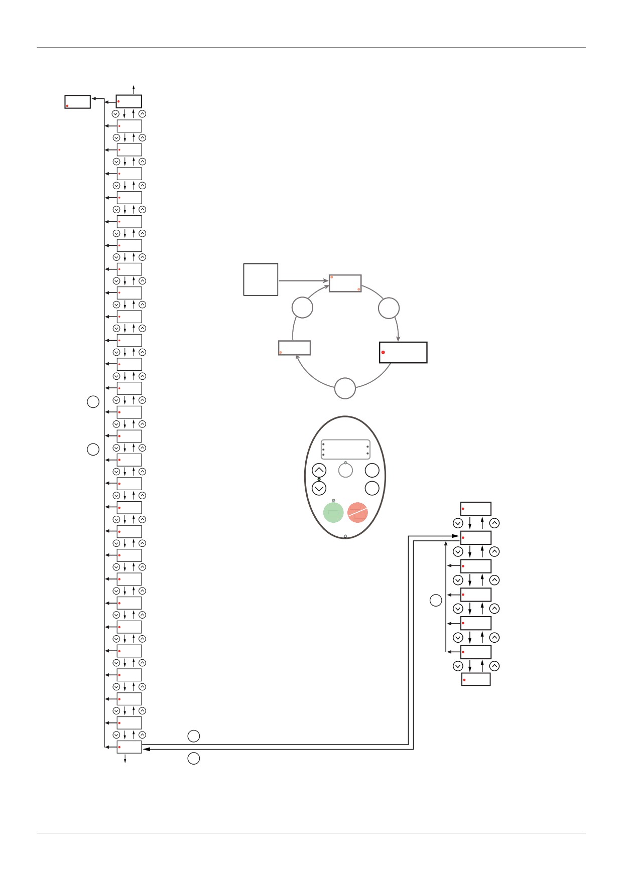
AUF [5 LAST PARAM CHANGE] submenu
to AUH
Programming
mode
Fr-F
AUF
SUBMENU [Quick menu]
GrU
SUBMENU [ALL PARAM CHANGE]
F---
SUBMENU [EXTENDED MENU]
IO
SUBMENU [I/O MENU]
COM
SUBMENU [COMMUNICATION MENU]
SCr
SUBMENU [SCROLL MENU]
PM
SUBMENU [PM MOTOR MENU]
Sr7
[Preset speed 7]
RUN
Power
UP
0.0
OLM
[Motor overload prot]
Hz
MODE
MODE
tHr
[Motor thermal prot.]
ub
[Mot Voltage Boost]
Fr - F
MON
PRG
AUF
Pt
[Mot cont. mode sel.]
uLu
[Motor rated voltage]
MODE
MODE
uL
[Motor rated freq.]
LL
[Low limit frequency]
RUN
MODE
PRG
%
MON
Hz
UL
[Upper limit freq]
Loc
MODE
Rem
FH
[Max frequency]
ENT
SUBMENU
[5 LAST PARAM CHANGE]
dEC
[Deceleration time 1]
STOP
(1)
RUN
HEAd
RESET
ACC
[Acceleration time 1]
(xxx)
Fr
[Local mot. Direction]
(xxx)
tYP
[Parameter reset]
(xxx)
[AO scaling]
MODE
FM
(xxx)
FMSL
[AO funct. selection]
FMOd
[Frequency mode sel]
(xxx)
CMOd
[Command mode sel]
End
(1)
AU4
[Auto set function]
AU1
[Auto ramp]
ENT
AUH
MODE
to AUF
(xxx)
Code of 5 last
parameters
Note: If no parameter has been changed, AU1 is selected.
(1) Flashes three times then displays previous parameter.
25
Overview
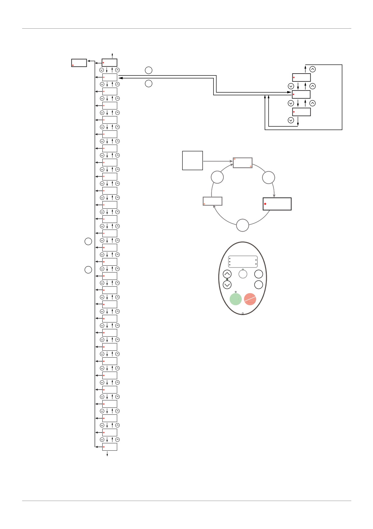
GrU [ALL PARAM CHANGE] submenu
to AUH
Programming
mode
SUBMENU
[ALL PARMCHANGE]
Fr-F
AUF
SUBMENU [Quick menu]
(4)
ENT
GrU
(1)
U--F
[Forward search]
MODE
to GrU
F---
SUBMENU [EXTENDED MENU]
[Waiting search]
U---
(3)
IO
SUBMENU [I/O MENU]
(2)
U--r
[Reverse search]
COM
SUBMENU [COMMUNICATION MENU]
(4)
SCr
SUBMENU [SCROLL MENU]
PM
SUBMENU [PM MOTOR MENU]
RUN
Power
Sr7
[Preset speed 7]
UP
0.0
Hz
OLM
[Motor overload prot]
MODE
MODE
tHr
[Motor thermal prot.]
Fr - F
ub
[Mot Voltage Boost]
MON
PRG
AUF
Pt
[Mot cont. mode sel.]
MODE
uLu
[Motor rated voltage]
MODE
uL
[Motor rated freq.]
RUN
%
LL
[Low limit frequency]
PRG
MON
Hz
MODE
Loc
Rem
MODE
UL
[Upper limit freq]
ENT
FH
[Max frequency]
STOP
RUN
RESET
dEC
[Deceleration time 1]
ACC
[Acceleration time 1]
Fr
[Local mot. Direction]
tYP
[Parameter reset]
FM
[AO scaling]
FMSL
[AO funct. selection]
FMOd
[Frequency mode sel]
(1) Pressing the UP key searches the parameter list starting
[Command mode sel]
CMOd
with the first one changed.
(2) Pressing the DOWN key searches the parameter list
[Auto set function]
AU4
starting with the last one changed.
AU1
[Auto ramp]
(3) The number of parameters displayed within the GrU
menu depends upon how many have been altered from their
factory settings.
AUH
SUBMENU [5 LAST PARAM CHANGE]
(4) When all the changed parameters have been displayed,
to AUF
the display returns to GrU.
26
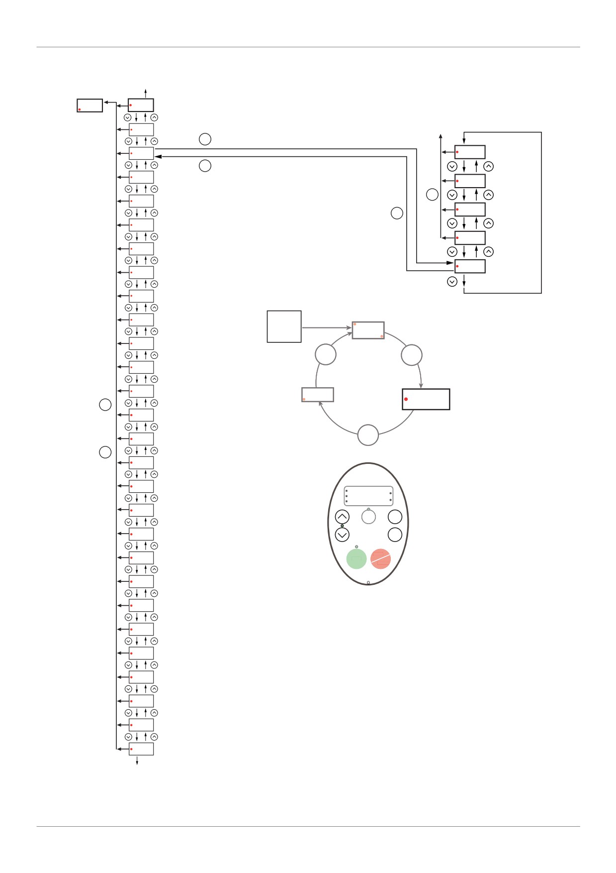
Overview
F--- [EXTENDED MENU] submenu
to AUH
Programming
mode
Fr-F
AUF
SUBMENU [Quick menu]
SUBMENU
[EXTENDE ENU]
GrU
SUBMENU [ALL PARAM CHANGE]
to F---
ENT
F---
F912
[Reserved]
MODE
IO
SUBMENU [I/O MENU]
F...
MODE
COM
SUBMENU [COMMUNICATION MENU]
F102
[Freq.2 bandw.]
MODE
SCr
SUBMENU [SCROLL MENU]
F101
[Freq. 2 reached]
PM
SUBMENU [PM MOTOR MENU]
F100
[Freq. 1 reached]
Sr7
[Preset speed 7]
OLM
[Motor overload prot]
tHr
[Motor thermal prot.]
RUN
Power
UP
0.0
ub
[Mot Voltage Boost]
Hz
MODE
MODE
Pt
[Mot cont. mode sel.]
uLu
[Motor rated voltage]
Fr - F
MON
PRG
AUF
MODE
[Motor rated freq.]
uL
[Low limit frequency]
MODE
LL
MODE
UL
[Upper limit freq]
FH
[Max frequency]
RUN
%
PRG
MON
Hz
dEC
[Deceleration time 1]
Loc
MODE
Rem
[Acceleration time 1]
ACC
ENT
[Local mot. Direction]
STOP
Fr
RUN
RESET
tYP
[Parameter reset]
FM
[AO scaling]
FMSL
[AO funct. selection]
FMOd
[Frequency mode sel]
[Command mode sel]
CMOd
AU4
[Auto set function]
AU1
[Auto ramp]
AUH
SUBMENU [5 LAST PARAM CHANGE]
to AUF
27
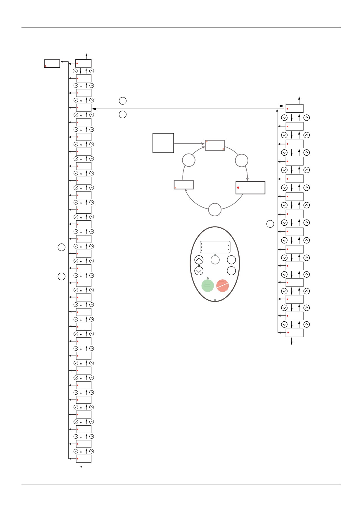
Overview
IO [I/O MENU] submenu
Programming
to AUH
mode
Fr-F
AUF
SUBMENU [Quick menu]
GrU
SUBMENU [ALL PARAM CHANGE]
F---
SUBMENU [EXTENDED MENU]
to F108
SUBMENU
ENT
[I/O MN]
IO
[AO funct. selection]
FMSL
MODE
COM
SUBMENU [COMMUNICATION MENU]
F147
[FL Relay delay]
SCr
SUBMENU [SCROLL MENU]
RUN
Power
[RY relay]
UP
0.0
F146
PM
SUBMENU [PM MOTOR MENU]
Hz
MODE
MODE
F139
[RY logic select.]
Sr7
[Preset speed 7]
F137
[RY Relay Function 2]
OLM
[Motor overload prot]
Fr - F
MON
PRG
AUF
tHr
[Motor thermal prot.]
[FL Relay Function]
F132
ub
[Mot Voltage Boost]
MODE
F130
[RY Relay Function 1]
Pt
[Mot cont. mode sel.]
MODE
F118
[VIA LI selection]
uLu
[Motor rated voltage]
RUN
%
MODE
PRG
MON
Hz
F113
[LI RES selection]
uL
[Motor rated freq.]
Loc
Rem
MODE
[Low limit frequency]
F112
[LI R selection]
LL
ENT
MODE
UL
[Upper limit freq]
STOP
F111
[LI F selection]
RUN
RESET
FH
[Max frequency]
F110
[Logic Funct 2 active]
dEC
[Deceleration time 1]
F109
[VIA selection]
ACC
[Acceleration time 1]
F108
[Logic Funct 1 active]
Fr
[Local mot. Direction]
to FMSL
tYP
[Parameter reset]
[AO scaling]
FM
FMSL
[AO funct. selection]
FMOd
[Frequency mode sel]
CMOd
[Command mode sel]
AU4
[Auto set function]
AU1
[Auto ramp]
AUH
SUBMENU [5 LAST PARAM CHANGE]
to AUF
28
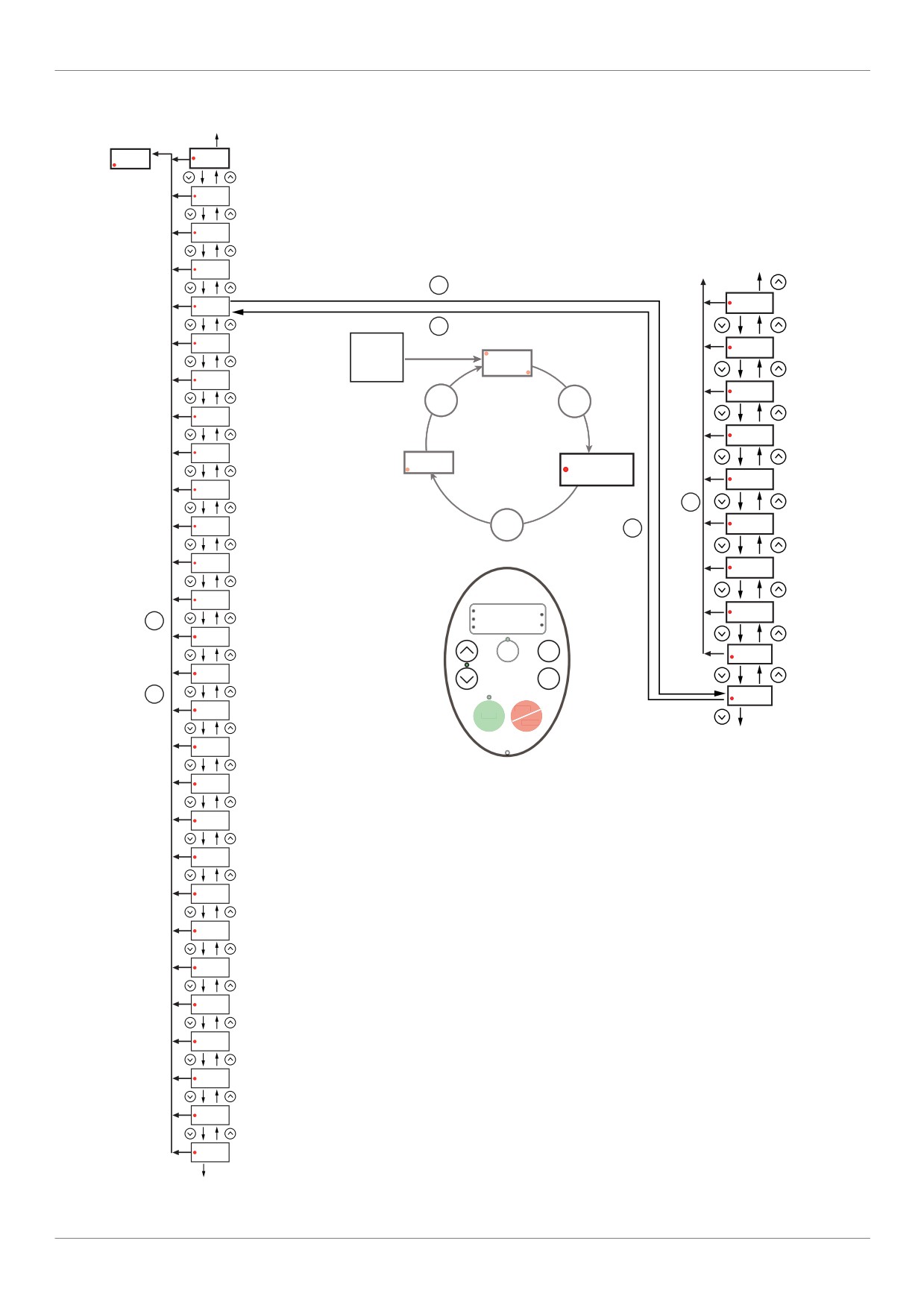
Overview
COM [COMMUNICATION MENU] submenu
to AUH
Fr-F
AUF
SUBMENU [Quick menu]
GrU
SUBMENU [ALL PARAM CHANGE]
F---
SUBMENU [EXTENDED MENU]
SUBMENU
[COMMUNCTION MENU]
to F800
IO
SUBMENU [I/O MENU]
to COM
ENT
COM
F851
[Com. fault setting]
MODE
SUBMENU
SCr
RUN
[SCROLL MENU]
Power
F896
[Max info frames]
UP
0.0
SUBMENU
PM
[PM MOTOR MENU]
Hz
F89.
MODE
MODE
Sr7
[Preset speed 7]
F890
[Network adress]
OLM
[Motor overload prot]
Fr - F
MON
PRG
AUF
F829
[Network protocol]
tHr
[Motor thermal prot.]
MODE
ub
[Mot Voltage Boost]
MODE
F821
[Mdb network parity]
MODE
Pt
[Mot cont. mode sel.]
F820
[Mdb network baud]
uLu
[Motor rated voltage]
RUN
%
F803
[Comm. time out]
MODE
PRG
MON
Hz
uL
[Motor rated freq.]
Loc
MODE
Rem
F80.
LL
[Low limit frequency]
ENT
MODE
F800
[Mdb RJ45 baud]
UL
[Upper limit freq]
STOP
RUN
RESET
to F851
FH
[Max frequency]
dEC
[Deceleration time 1]
ACC
[Acceleration time 1]
Fr
[Local mot. Direction]
tYP
[Parameter reset]
FM
[AO scaling]
FMSL
[AO funct. selection]
FMOd
[Frequency mode sel]
CMOd
[Command mode sel]
AU4
[Auto set function]
AU1
[Auto ramp]
AUH
SUBMENU [5 LAST PARAM CHANGE]
to AUF
29
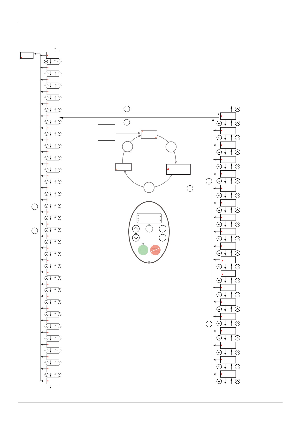
Overview
SCr [SCROLL MENU] submenu 1
Programming
to AUH
mode
Fr-F
AUF
SUBMENU [Quick menu]
GrU
SUBMENU [ALL PARAM CHANGE]
F---
SUBMENU [EXTENDED MENU]
SUBMENU
IO
SUBMENU [I/O MENU]
[SCROLL MENU]
To F251 see page
32
COM
SUBMENU [COMMUNICATION MENU]
ENT
SCr
F324
[Driving scroll]
MODE
to SCr
SUBMENU
PM
[PM MOTOR MENU]
RUN
Power
F311
[Motor direction]
0.0
UP
Sr7
[Preset speed 7]
Hz
pt
[Mot cont. mode sel.]
MODE
MODE
OLM
[Motor overload prot]
uLu
[Motor Rated Voltage]
tHr
[Motor thermal prot.]
Fr - F
MON
PRG
AUF
uL
[Motor rated freq.]
ub
[Mot Voltage Boost]
MODE
Pt
[Mot cont. mode sel.]
MODE
MODE
F415
[Motor rated current]
uLu
[Motor rated voltage]
F417
[Motor rated speed]
MODE
uL
[Motor rated freq.]
RUN
%
[Motor Current Limit]
PRG
F601
MON
Hz
LL
[Low limit frequency]
Loc
Rem
MODE
MODE
LL
[Low limit frequency]
UL
[Upper limit freq]
ENT
UL
[Upper limit freq]]
FH
[Max frequency]
STOP
RUN
RESET
dEC
[Deceleration time 1]
FH
[Max frequency]
ACC
[Acceleration time 1]
F401
[Slip Compensation]
Fr
[Local mot. Direction]
F402
[Auto Torque Boost]
tYP
[Parameter reset]
dEC
[Deceleration time 1]
FM
[AO scaling]
[Acceleration time 1]
ACC
FMSL
[AO funct. selection]
MODE
F505
[Commut. ramp freq.]
FMOd
[Frequency mode sel]
CMOd
[Command mode sel]
[Deceleration time 1]
F501
AU4
[Auto set function]
F500
[Acceleration time 2 ]
AU1
[Auto ramp]
[Auto-tuning drive]
F400
AUH
SUBMENU [5 LAST PARAM CHANGE]
to F458 see page 31
to AUF
30
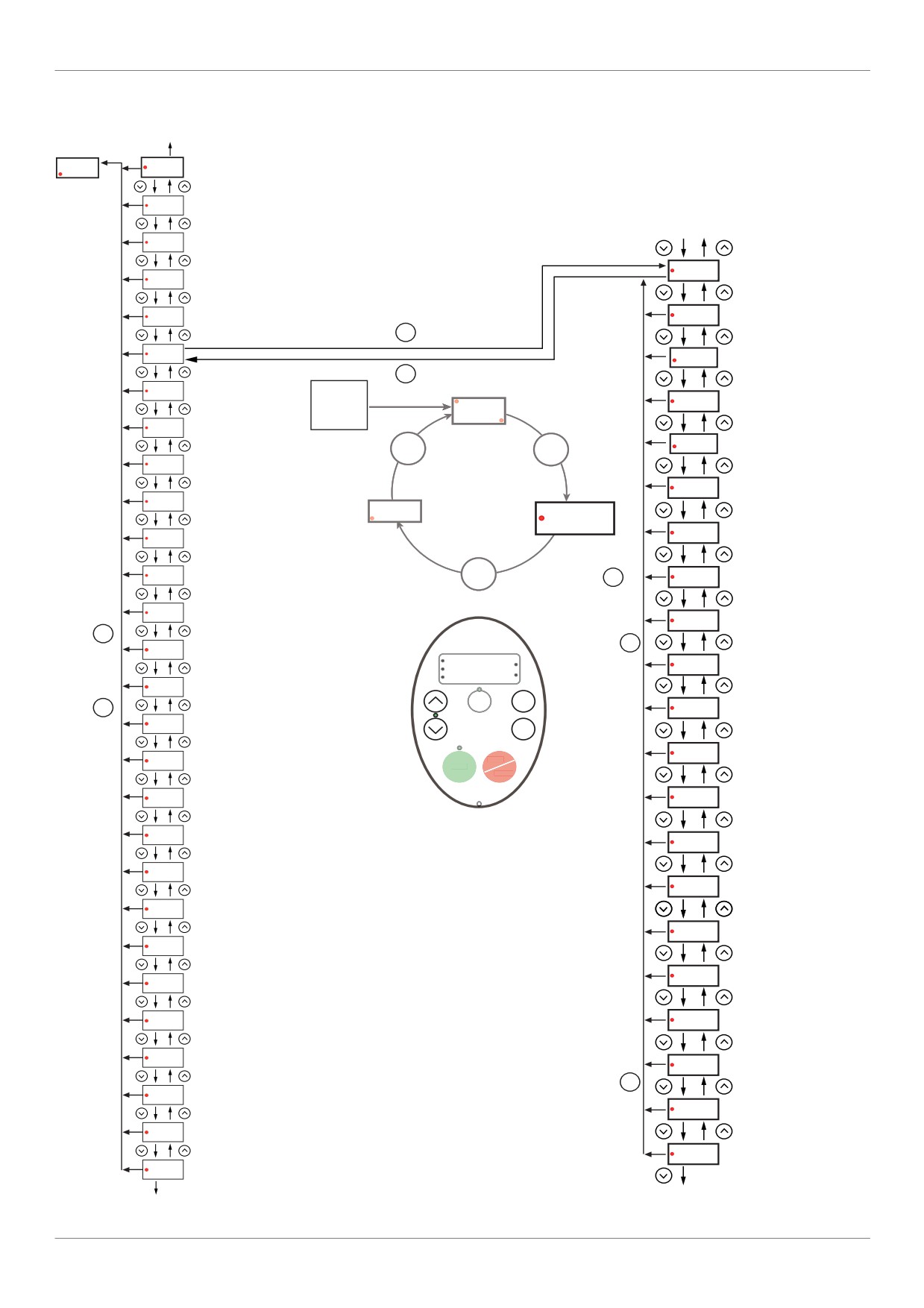
Overview
SCr [SCROLL MENU] submenu 2
Programming
to AUH
mode
Fr-F
AUF
SUBMENU [Quick menu]
SUBMENU
GrU
SUBMENU [ALL PARAM CHANGE]
[SCROLL MENU]
to F400 see page
30
F---
SUBMENU [EXTENDED MENU]
F458
[Current loop gain]
IO
SUBMENU [I/O MENU]
to SCr
COM
SUBMENU [COMMUNICATION MENU]
F418
[Frequency loop gain]
ENT
SCr
F419
[Freq. loop stability]]
MODE
SUBMENU
PM
[PM MOTOR MENU]
RUN
Power
F495
[Motor voltage coef.]
UP
0.0
Sr7
[Preset speed 7]
Hz
F915
[PM mode selection]
MODE
MODE
OLM
[Motor overload prot]
F912
[Autotune L q-axis]
tHr
[Motor thermal prot.]
Fr - F
MON
PRG
AUF
F913
[Autotune L d-axis]
ub
[Mot Voltage Boost]
Pt
[Mot cont. mode sel.]
MODE
MODE
F916
[PM Align cur. Level]
uLu
[Motor rated voltage]
F921
[Init. Pos. Current]
MODE
MODE
uL
[Motor rated freq.]
RUN
%
PRG
F420
[Torque Boost Coef]
MON
Hz
LL
[Low limit frequency]
Loc
MODE
MODE
Rem
[RY Relay Function 1]
F130
UL
[Upper limit freq]
ENT
F132
[FL Relay Function]
FH
[Max frequency]
STOP
RUN
RESET
dEC
[Deceleration time 1]
F101
[Freq. 2 reached]
ACC
[Acceleration time 1]
F102
[Freq.2 bandw.]
Fr
[Local mot. Direction]
F113
[LI RES selection]
tYP
[Parameter reset]
F303
[Number auto reset]
FM
[AO scaling]
F325
[Pre-start Scroll]
FMSL
[AO funct. selection]
FMOd
[Frequency mode sel]
F326
[Pre-Start time]
CMOd
[Command mode sel]
F327
[Pre-Start speed]
MODE
AU4
[Auto set function]
F328
[LL speed time]
AU1
[Auto ramp]
F329
[Pre-Start delay]
AUH
SUBMENU [5 LAST PARAM CHANGE]
to AUF
to F330 see page 32
31
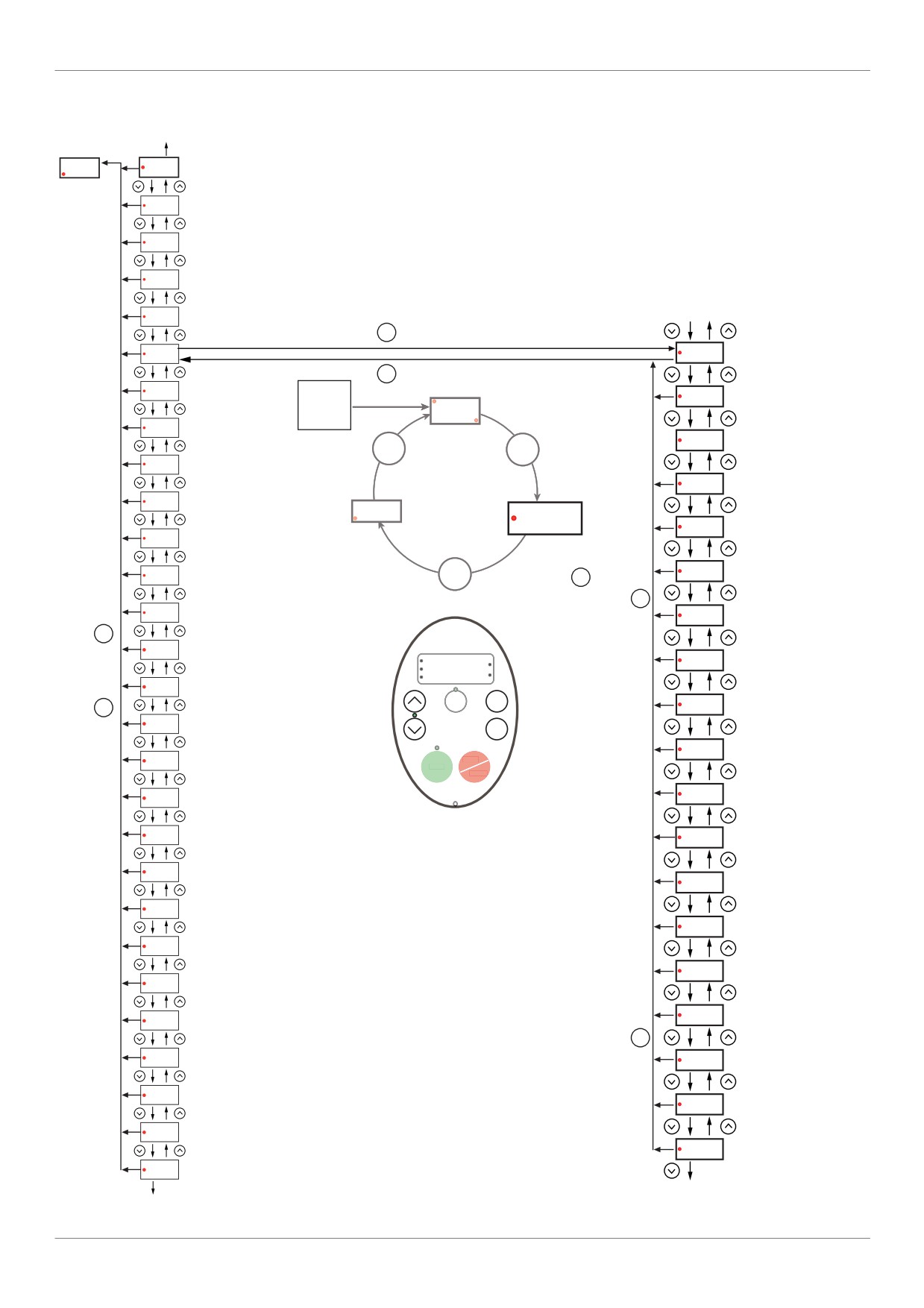
Overview
SCr [SCROLL MENU] submenu 3
Programming
to AUH
mode
Fr-F
AUF
SUBMENU [Quick menu]
GrU
SUBMENU [ALL PARAM CHANGE]
F---
SUBMENU [EXTENDED MENU]
SUBMENU
[SCROLL MENU]
IO
SUBMENU [I/O MENU]
to F329 see page
31
COM
SUBMENU [COMMUNICATION MENU]
ENT
SCr
F330
[Std Oiling Cycle]
MODE
to SCr
PM
SUBMENU
[PM MOTOR MENU]
RUN
F331
[Std Oiling Speed]
Power
UP
0.0
Sr7
[Preset speed 7]
Hz
F332
[Std Oiling Time]
MODE
MODE
OLM
[Motor overload prot]
F333
[Std Oil. Cycle Frq.]
tHr
[Motor thermal prot.]
Fr - F
MON
PRG
AUF
F334
[Low Speed Oiling]
ub
[Mot Voltage Boost]
[LL Speed for Oiling]
Pt
MODE
F335
[Mot cont. mode sel.]
MODE
MODE
uLu
[Motor rated voltage]
F336
[LL Time for Oiling]
MODE
uL
[Motor rated freq.]
RUN
[Oiling Time at LLS]
F337
%
PRG
MON
Hz
LL
[Low limit frequency]
Loc
MODE
MODE
Rem
F338
[Scroll Protection]
UL
[Upper limit freq]
ENT
[Cavitation Frq.]
F339
FH
[Max frequency]
STOP
RUN
RESET
[Discharge Gas]
dEC
[Deceleration time 1]
F349
ACC
[Acceleration time 1]
[Hight Tresh.]
F350
Fr
[Local mot. Direction]
[Cooling Frq.]
F351
tYP
[Parameter reset]
[Cooling Time]
F352
FM
[AO scaling]
[Hight hight Tresh.]
F353
FMSL
[AO funct. selection]
[Re-Start Delay]
F354
FMOd
[Frequency mode sel]
MODE
CMOd
[Command mode sel]
F355
[Crankcase Heating]
AU4
[Auto set function]
[DC brake start freq.]
F250
AU1
[Auto ramp]
F251
[DC braking current]
AUH
SUBMENU [5 LAST PARAM CHANGE]
To F324 see page 30
to AUF
32
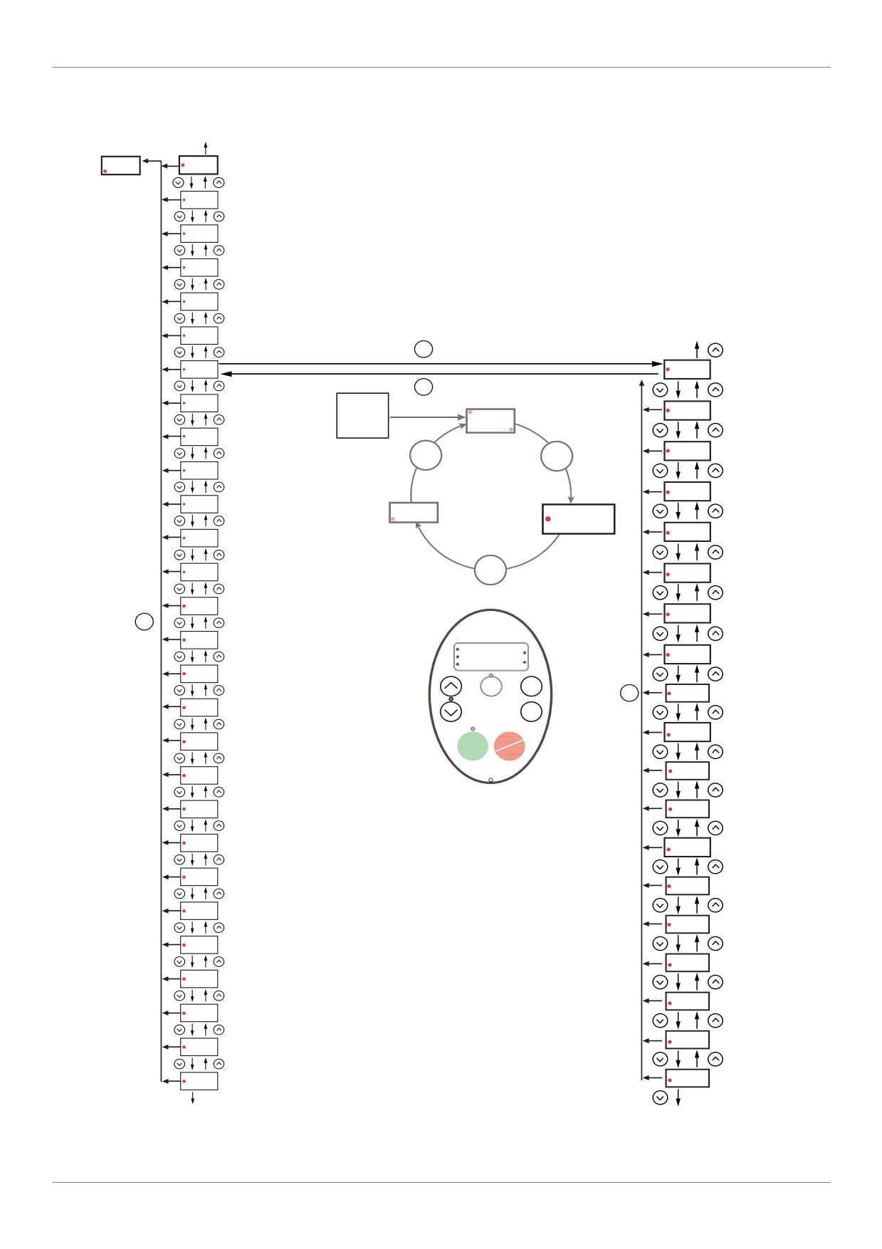
Overview
PM [PM MOTOR MENU] submenu
to AUH
Fr-F
AUF
SUBMENU [Quick menu]
GrU
SUBMENU [ALL PARAM CHANGE]
F---
SUBMENU [EXTENDED MENU]
IO
SUBMENU [I/O MENU]
SUBMENU
COM
[PM MOTOR MENU]
SUBMENU [COMMUNICATION MENU]
to F420
SCr
SUBMENU [SCROLL MENU]
ENT
PM
Pt
[Motor thermal prot.]
MODE
to PM
Sr7
[Preset speed 7]
RUN
Power
uLu
[Motor rated voltage]
UP
0.0
OLM
[Motor overload prot]
Hz
uL
[Motor rated freq.]
MODE
MODE
tHr
[Motor thermal prot.]
F405
[Motor rated cap.]
ub
[Mot Voltage Boost]
Fr - F
MON
PRG
AUF
F415
[Motor rated current]
Pt
[Mot cont. mode sel.]
uLu
MODE
[Motor rated voltage]
F417
[Motor rated speed]
uL
[Motor rated freq.]
F400
[Auto-tuning drive]]
MODE
LL
[Low limit frequency]
RUN
%
PRG
F458
[Current loop gain]
MON
Hz
UL
[Upper limit freq]
Loc
MODE
Rem
MODE
F418
[Frequency loop gain]
FH
[Max frequency]
ENT
[Freq. loop stability]
F419
dEC
[Deceleration time 1]
STOP
RUN
RESET
[Motor voltage coef.]
ACC
[Acceleration time 1]
F495
Fr
[Local mot. Direction]
F936
[Saliency Level]
tYP
[Parameter reset]
F915
[PM mode selection]
FM
[AO scaling]
F402
[Auto Torque Boost]
FMSL
[AO funct. selection]
F912
[Autotune L q-axis]
FMOd
[Frequency mode sel]
F913
[Autotune L d-axis]
CMOd
[Command mode sel]
F916
[PM Align cur. Level]
AU4
[Auto set function]
F921
[Init. Pos. Current]
AU1
[Auto ramp]
AUH
SUBMENU [5 LAST PARAM CHANGE]
F420
[Torque Boost Coef]
to AUF
to Pt
33
Overview
Submenus
The ATV212 drive features 6 submenus (see diagrams starting on page 24) that are designed to reduce the time and
effort required to program application parameters. Parameters can be modified within these submenus.
AUH [5 LAST PARAM CHANGE]
The AUH submenu displays, in reverse chronological order, the last 5 parameters that have been changed from their
factory settings. Each time the AUH submenu is accessed, it searches for the latest parameters changed from their
factory settings. If every parameter is at its factory settings, no display is generated.
Parameter Lock F700 is not displayed in the AUH menu, even if its value has been changed (see page 68).
AUF [QUICK MENU]
The AUF submenu provides ready access to the ten basic parameters commonly used in programming the drive. In
many cases, programming the ATV212 drive is complete when these 10 parameters have been properly set (see
chapter Quick Menu page 59).
GrU [ALL PARAM CHANGE]
The GrU submenu displays every parameter that has been changed from its factory settings. Each time the GrU
submenu is accessed, its content is refreshed with the latest list of parameters changed from their factory settings. If
every parameter is at its factory setting, no display is generated.
Parameters Fn and F470 - F473 are not displayed in the GrU menu, even if their values have been changed.
F- - - [EXTENDED MENU]
The extended parameter submenu provides access to parameters used for special settings and applications.
10 [I/O MENU]
The IO submenu provides access to parameters used for input/output setting.
COM [COMMUNICATION MENU]
The COM submenu provides access to parameters used for the communication setting.
SCr [SCROLL MENU]
The SCr submenu provides access to parameters used for the Synchronous scroll motors setting.
PM [PM CONTROL MENU]
The PM submenu provides access to parameters used for the Synchronous motor setting.
34
Overview
Graphic display option
WARNING
LOSS OF CONTROL
Do not use the ATV21 and ATV12 terminal display (VW3A21101 and VW3A1006).
Only VW3A1101 is compatible with ATV212.
Failure to follow these instructions can result in death, serious injury, or equipment damage.
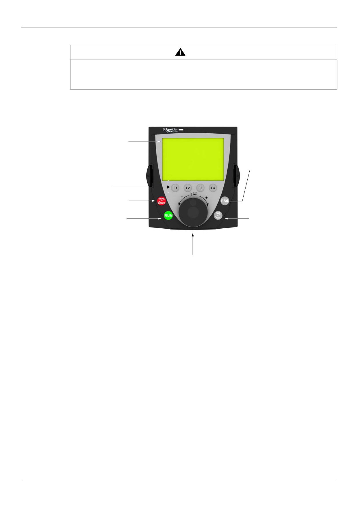
Description of the graphic display option
With the graphic display option, which works with FLASH V1.1IE29 or higher, it is possible to display more text
information than can be shown on the integrated display terminal.
1 Graphic display
7 ESC key: Press to select the
graphic display mode.
- Run mode (default on power-up)
2 Function keys
- Programming mode
F1, F2 and F3: not
- Monitoring mode
assigned
Can also be used to go back to
F4: Loc/Rem
the previous menu.
Also corresponds to the MODE
3 STOP/RESET key
button of the embedded HMI
4 RUN key
6 FWD/REV key: Press to
reverse the direction of rotation of
the motor
5 Jog dial:
• Press (ENT):
- To save the current value
- To enter the selected menu or parameter
• Turn +/-:
- To increment or decrement a value
- To go to the next or previous line
- To increase or decrease the reference if control via the graphic
display option is activated
Note: Keys 3, 4, 5 and 6 can be used to control the drive directly, if control via the graphic display option is
activated.
35
Overview
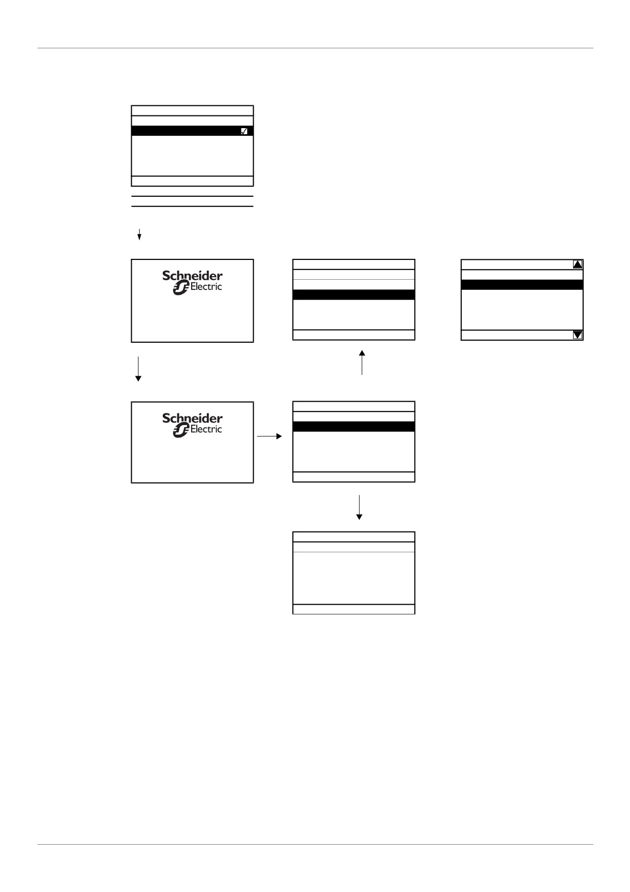
Powering up the drive with graphic display option for the first time
When powering up the graphic display option for the first time, the user has to select the required language.
LANGUAGE
Display after the graphic display option has been powered up for the first time.
English
Select the language and press ENT.
Français
Deutsch
Italiano
Español
Chinese
Русский
Türkçe
ENT
MAIN MENU
LANGUAGE
DRIVE MENU
ENT
English
LANGUAGE
French
Connection in Progress
Spanish
German
V1.2IE12
Chinese
The graphic display option to drive
Move
synchronization screen will now ap-
up/down keys
pear.
MAIN MENU
DRIVE MENU
LANGUAGE
ATV212H075M3X
0.75kW/1HP 200 / 240 V
2 s or ENT
OPERATIONAL VALUE
0 Hz
Rem
Loc/Rem
36
Overview
Finding a parameter in this document
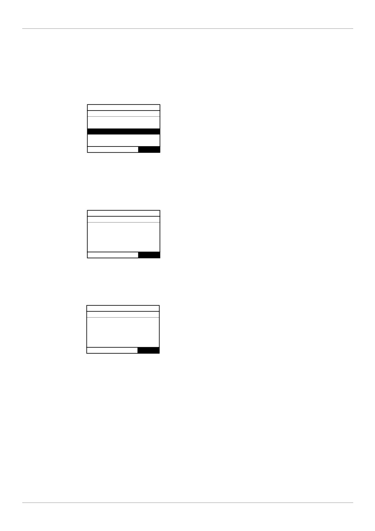
The following assistance with finding explanations on a parameter is provided:
• With the integrated display terminal and the optional graphic display terminal : Direct use of the parameter
code index, page 203, to find the page giving details of the displayed parameter.
• With the graphic display option: The parameter code and the name are displayed.
Example: ACC
AUF: QUICK MENU
vLv: Motor rated voltage
AU1: Auto ramp
ACC: Acceleration time 1
DEC:Deceleration time 1
LL: Low limit frequency
Rem
Loc/Rem
Then use the parameter code index, page 203, to find the page giving details of the displayed parameter.
Detected fault screens
Example: Output phase loss fault
EPHO: Output phase loss fault
Loss of one or more output phases.
Determine the cause of the missing
output phase and rectify the problem.
Set parameter F605 to 0.
Rem
Loc/Rem
This screen is displayed the detected fault type and diagnostic information related to the detected fault. Then
use the alarm code table page 180 for more information.
Line undervoltage
OPERATIONAL VALUE
MOFF: Line Undervolt fault
Rem
Loc/Rem
37
Overview
Pre-alarms screens
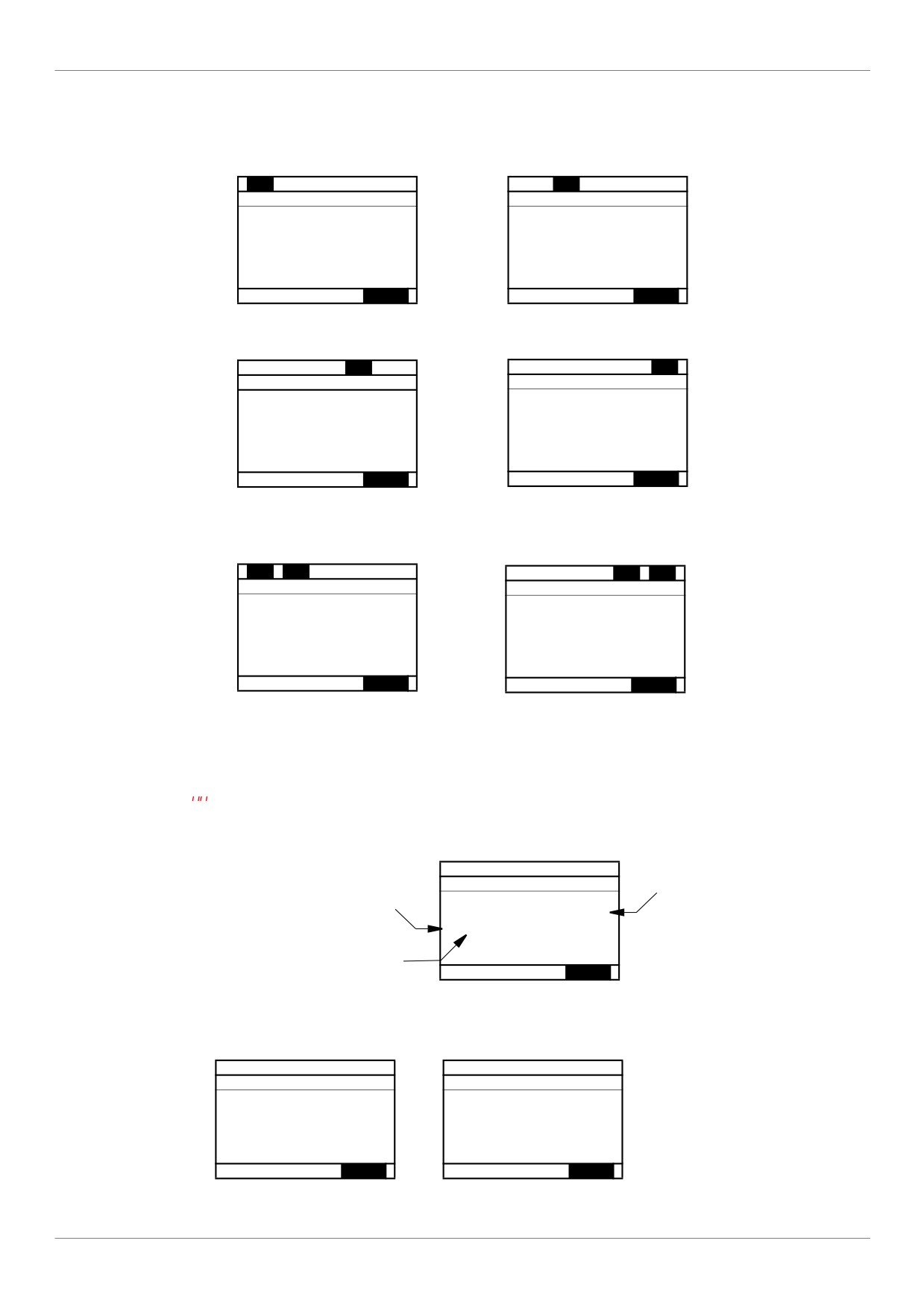
Here some type of screens:
Current Limit pre-alarm
DC bus overvoltage pre-alarm
Alarm C
Alarm P
Alarm P
OPERATIONAL VALUE
OPERATIONAL VALUE
29.0 Hz
29.0 Hz
Rem
Loc/Rem
Rem
Loc/Rem
Motor overload pre-alarm
Drive overheating pre-alarm
Alarm L
Alarm H
OPERATIONAL VALUE
OPERATIONAL VALUE
29.0 Hz
29.0 Hz
Rem
Loc/Rem
Rem
Loc/Rem
Current Limit and DC bus overvoltage
Motor overload and drive overheating
pre-alarm
pre-alarm
Alarm C
Alarm P
Alarm L
Alarm H
OPERATIONAL VALUE
OPERATIONAL VALUE
29.0 Hz
29.0 Hz
Rem
Loc/Rem
Rem
Loc/Rem
Modbus communication status
[Mdb com stat] (Mb
) parameter display
This parameter is able to check the modbus communication on RJ45 and OpenStyle port.
Without Communication
When Rx and/or Tx are
displayed in this row
Mdb com stat
B-A-COM:
their state is inactive
Mb activity
RJ45
B - A - COM
on OpenStyle port
Rx
Tx
Rx
Tx
RJ45:
Rem
Loc/Rem
Mb activity on RJ45 port
Example : With Communication on RJ45 port
Mdb com stat
Mdb com stat
RJ45
B - A - COM
RJ45
B - A - COM
Tx
Rx
Tx
Rx
Rx
Tx
Rx
Tx
Rem
Loc/Rem
Rem
Loc/Rem
38
Overview
SoMove software
Description
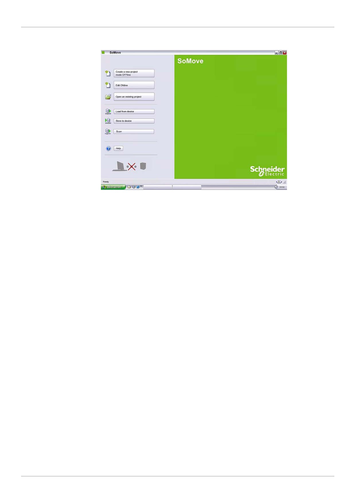
SoMove is user-friendly setup software PC for setting up Altivar 212 drives.
SoMove software incorporates various functions for the device setup phases, such as:
Configuration preparation
Start-up
Maintenance
It can be downloaded free of charge from the internet at www.schneider-electric.com.
Connection
SoMove software can use a direct USB/RJ45 cable link or a Bluetooth® wireless link.
See catalog on www.schneider-electric.com.
39
//////////////////////////////////////////