Altivar 212 Variable speed drives for synchronous and asynchronous motors. Programming Manual (2014) - page 2
Overview
Structure of the parameter tables
The parameter tables contained in the descriptions of the various menus are organized as follows.
Example:
Code
Name / Description
Adjustment range
Factory setting
F400
[Auto-tuning drive] Auto tuning enable
-
0
0
[Disabled]
1
[Initialize constant]: Application of individual settings of Auto Torque Boost [Auto Torque Boost]
(F402)
2
[Complete tune]: complete auto tuning.
Parameter F400 is reset to “0” after the auto tuning is performed.
Value of parameter on graphic display option
Parameter value on embedded display
Name of parameter on graphic display option and description if needed.
Parameter code on 4-digit 7-segment display
Note: The text in square brackets [ ] indicates what you will see on the graphic display option.
40
Overview
Parameters that cannot be changed while the drive is running
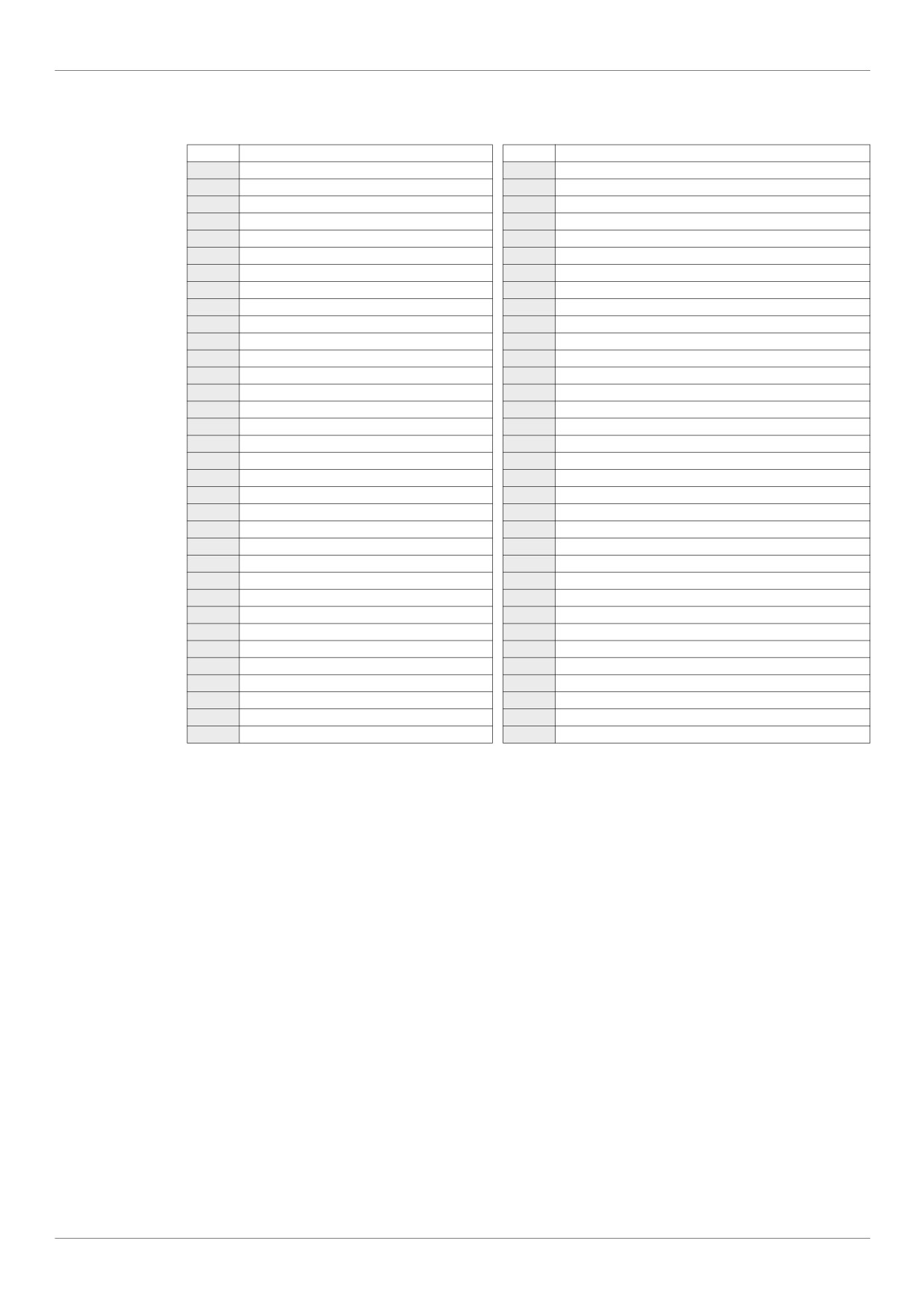
The table below lists the parameters that cannot be changed unless the drive is stopped.
Code
Description
Code
Description
AU1
[Auto ramp]
F338
[Scroll Protection]
AU4
[Auto set function]
F349
[Discharge gas]
CMOd
[Command mode sel]
F355
[Crankcase heating]
FMOd
[Frequency mode sel]
F400
[Auto-tuning drive]
tYp
[Parameter reset]
F405
[Motor rated cap.]
FH
[Max frequency]
F415
[Motor rated current]
UL
[Upper limit freq]
F416
[Mot no-load current]
uLu
[Motor rated voltage]
F417
[Motor rated speed]
Pt
[Mot cont. mode sel.]
F418
[Frequency loop gain]
F108
[Logic Funct 1 active]
F419
[Freq. loop stability]
F109
[VIA selection]
F458
[Current loop gain]
F110
[Logic Funct 2 active]
F480
[No load cur. coef]
F111
[LI F selection]
F481
[In noise comp. filter]
F112
[LI R selection]
F482
[In noise Inhibit filter]
F113
[LI RES selection]
F483
[In noise inhibit gain]
F118
[VIA LI selection]
F484
[Pwr supply adj. gain]
F130
[RY Relay Function 1]
F485
[Stall control coef. 1]
F132
[FL Relay Function]
F492
[Stall control coef. 2]
F137
[RY Relay Function 2]
F494
[Mot. adj coefficient]
F139
[RY logic select.]
F495
[Motor voltage coef.]
F170
[Mot 2 rated Freq.]
F496
[PWM adj. coef.]
F171
[Motor 2 rated Volt]
F601
[Motor Current Limit]
F300
[Switch. freq. level]
F603
[fault stop Mode]
F301
[Catch on fly]
F605
[Output phase loss]
F302
[Supply loss behav.]
F608
[Input phase loss]
F303
[Number auto reset]
F613
[Short circuit det.]
F305
[Overvoltage fault]
F626
[Overvoltage level]
F307
[Mot volt limitation]
F627
[Undervolt detect.]
F311
[Motor direction]
F732
[Loc/rem key]
F316
[Switch. freq. mode]
F915
[PM mode selection]
F324
[Driving Scroll]
F916
[PM Align cur. Level]
F325
[Pre-start Scroll]
F920
[Position Adjust]
F330
[Std Oiling Cycle]
F921
[Init. Pos. Current]
F334
[Low Speed Oiling]
41
Overview
Common control schemes
DANGER
HAZARD OF ELECTRIC SHOCK, EXPLOSION OR ARC FLASH
Read and understand the instructions in "before you begin" chapter, before performing the procedure in this
section.
Failure to follow these instructions will result in death or serious injury.
DANGER
UNINTENDED EQUIPMENT OPERATION
To modify the setting of the switches, the product must be switched off.
Do not change the setting of switch SW102 unless your system is properly wired.
Failure to follow these instructions will result in death or serious injury.
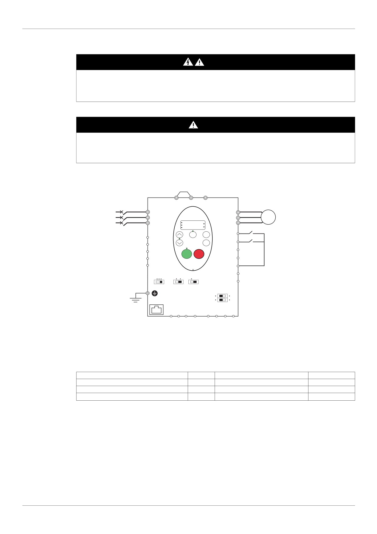
2-wire control
PO PA/+ PC/-
R/L1
U/T1
S/L2
V/T2
M
T/L3
RUN
W/T3
PRG
%
MON
Hz
Loc
Run forward
Rem
MODE
F
FLC
ENT
R
Run reverse
FLB
FLA
RES
RUN STOP
RYA
PLC
RYC
P24
FM
CC
PLC
I U
Term
Sink
Source
FM
SW102
SW101
SW103
VIA U
I
VIB U
PTC
SW100
B A GND SCR
PP
VIA VIB CC
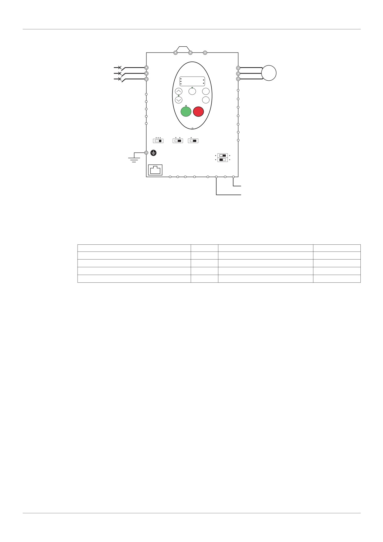
1. Wire the logic inputs as indicated in the above figure.
2. Set switch SW102 to source.
3. Program common parameters of ATV212 (see Quick Menu page 59).
4. Program specific parameters for 2-wire control as indicated in the following table:
Parameter
Page
Setting
Factory value
CMOd [Command mode sel]
87
0 [Logic inputs]
0
F111 [LI F selection]
100
2 [forward]
2
F112 [LI R selection]
100
3 [reverse]
6
Note: If F111 and F112 are switched simultaneously, the drive will go at 0 speed.
42
Overview
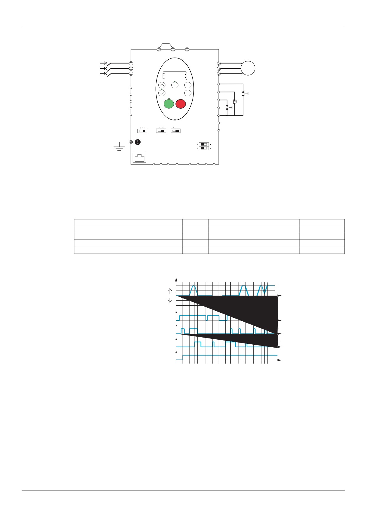
3-wire control
PO PA/+ PC/-
R/L1
U/T1
S/L2
V/T2
M
T/L3
RUN
W/T3
PRG
%
MON
Hz
Loc
Rem
MODE
F
FLC
ENT
R
FLB
Start forward
FLA
RES
RUN STOP
Stop
RYA
PLC
Start reverse
RYC
P24
FM
CC
PLC
I U
Term
Sink
Source
FM
SW102
SW101
SW103
VIA U
I
VIB U
PTC
SW100
B A GND SCR
PP
VIA VIB CC
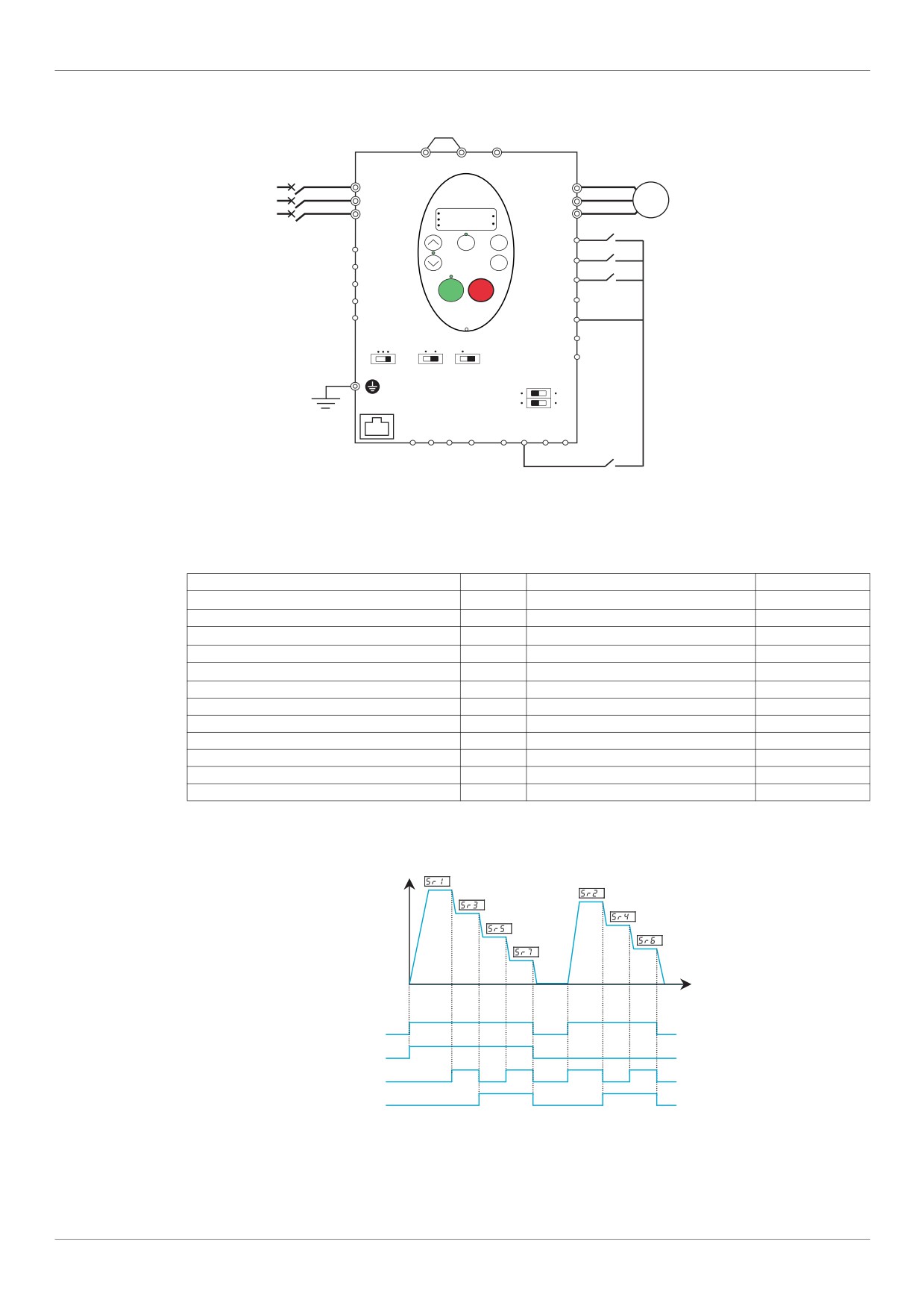
1. Wire the logic inputs as indicated in the above figure.
2. Set switch SW102 to source.
3. Program common parameters of ATV212 (see Quick Menu page 59).
4. Program specific parameters for 3-wire control as indicated in the following table:
Parameter
Page
Setting
Factory value
CMOd [Command mode sel]
87
0 [Logic inputs]
0
F111 [LI F selection]
100
2 [forward]
2
F112 [LI R selection]
100
49 [3-wire]
6
F113 [LI RES selection]
100
3 [reverse]
10
3 wire control timing diagram
Output frequency
Forward run
0
Reverse run
ON
R - Stop
OFF
ON
F - Forward start
OFF
ON
RES - Reverse start
OFF
ON
Line power
OFF
43
Overview
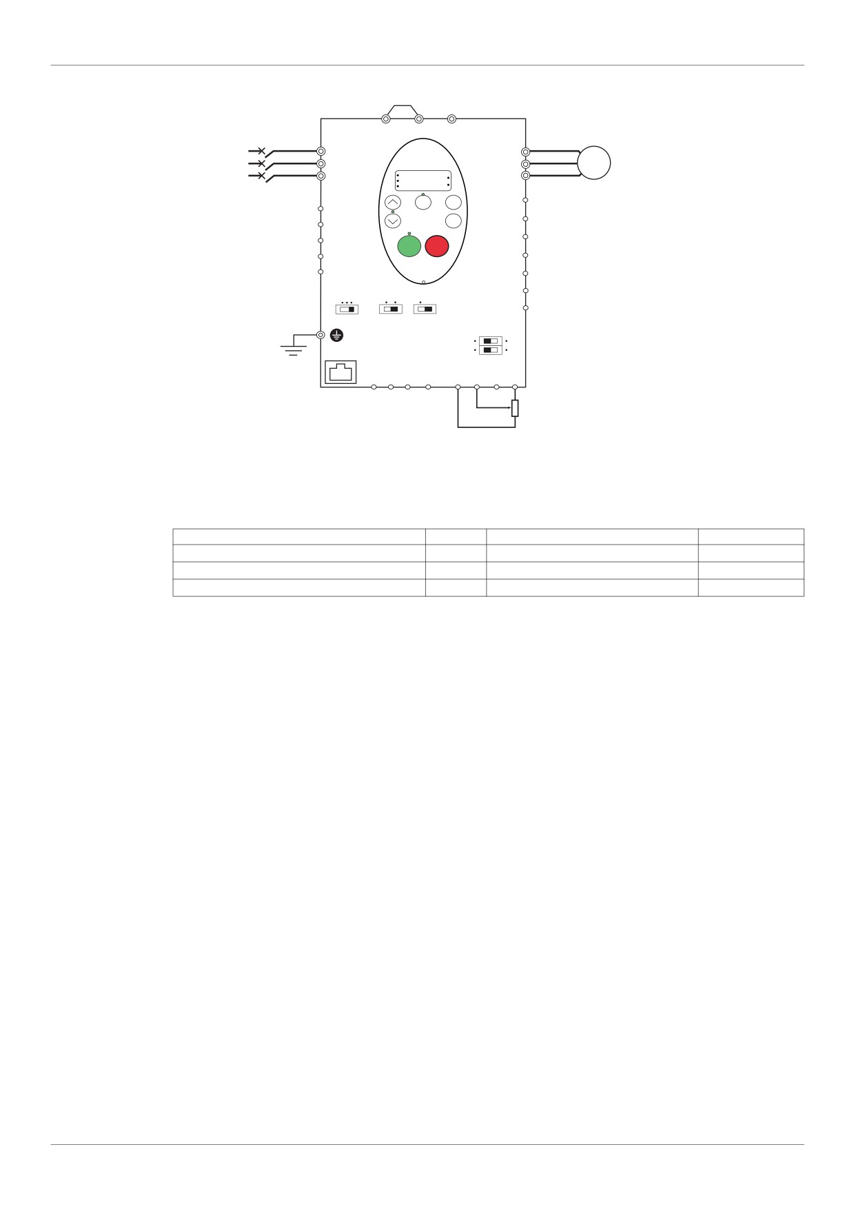
External speed control potentiometer
PO PA/+ PC/-
R/L1
U/T1
S/L2
V/T2
M
T/L3
RUN
W/T3
PRG
%
MON
Hz
Loc
MODE
Rem
F
FLC
ENT
R
FLB
FLA
RES
RUN STOP
RYA
PLC
RYC
P24
FM
CC
PLC
I U
Term
Sink
Source
FM
SW102
SW101
SW103
VIA U
I
VIB U
PTC
SW100
B A GND SCR
PP
VIA VIB CC
2.2 to 10 kOhms
1/4 Watt
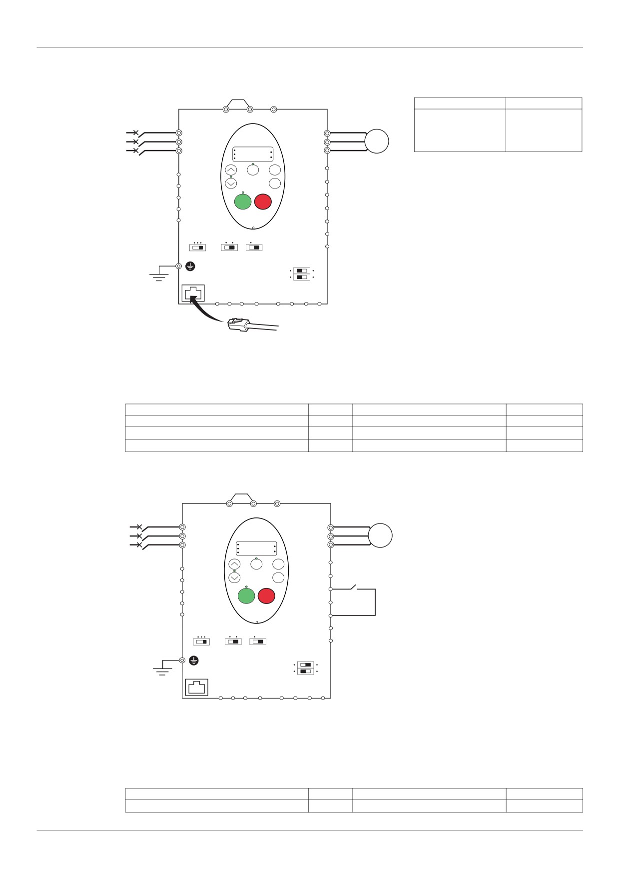
1. Wire the analog input as indicated in the above figure.
2. Set switch SW100 to V (voltage).
3. Program common parameters of ATV212 (see Quick Menu page 59).
4. Program specific parameters for external speed control potentiometer as indicated in the following table:
Parameter
Page
Setting
Factory value
FMOd [Frequency mode sel]
87
1 [Ref source VIA]
1
F109 [VIA selection]
100
0 [AI]
0
F200 [Auto/man speed ref]
118
0 [Enable]
0
44
Overview
4-20 mA speed control
PO PA/+ PC/-
R/L1
U/T1
S/L2
V/T2
M
T/L3
RUN
W/T3
PRG
%
MON
Hz
Loc
MODE
Rem
F
FLC
ENT
R
FLB
FLA
RES
RUN STOP
RYA
PLC
RYC
P24
FM
CC
PLC
I U
Term
Sink
Source
FM
SW102
SW101
SW103
VIA U
I
VIB U
PTC
SW100
B A GND SCR
PP
VIA VIB CC
4-20 mAcurrent signal
1. Wire the analog input as indicated in the above figure.
2. Set switch SW100 to I (current).
3. Program common parameters of ATV212 (see Quick Menu page 59).
4. Program specific parameters for 4-20 mA speed control as indicated in the following table:
Parameter
Page
Setting
Factory value
FMOd [Frequency mode sel]
87
1 [Ref source VIA]
1
F109 [VIA selection]
100
0 [AI]
0
F200 [Auto/man speed ref]
118
0 [Enable]
0
F201 [VIA ref point 1]
116
20 %
0 %
45
Overview
Preset speeds (up to seven)
PO PA/+ PC/-
R/L1
U/T1
S/L2
V/T2
M
T/L3
RUN
W/T3
PRG
%
MON
Hz
Loc
MODE
Rem
F
FLC
ENT
R
FLB
FLA
RES
RUN STOP
RYA
PLC
RYC
P24
FM
CC
PLC
I U
Term
Sink
Source
FM
SW102
SW101
SW103
VIA U
I
VIB U
PTC
SW100
B A GND SCR
PP
VIA VIB CC
1. Wire the logic and analog inputs as indicated in the above figure.
2. Set switch SW102 to source.
3. Program common parameters of ATV212 (see Quick Menu page 59).
4. Program specific parameters for preset speed as indicated in the following table:
Parameter
Page
Setting
Factory value
F109 [VIA selection]
100
2 [LI source]
0
F111 [LI F selection]
100
2 [forward]
2
F112 [LI R selection]
100
6 [PS1]
6
F113 [LI RES selection]
100
7 [PS2]
10
F118 [VIA LI selection]
100
8 [PS3]
7
Sr1 [Preset speed 1]
123
-
15.0
Sr2 [Preset speed 2]
123
-
20.0
Sr3 [Preset speed 3]
123
-
25.0
Sr4 [Preset speed 4]
123
-
30.0
Sr5 [Preset speed 5]
123
-
35.0
Sr6 [Preset speed 6]
123
-
40.0
Sr7 [Preset speed 7]
123
-
45.0
Example of 7-step preset speed operation:
Output
frequency
(Hz)
0
Time (sec)
ON
F
OFF
ON
R
OFF
ON
RES
OFF
ON
VIA
OFF
See page 123 for additionnal information.
46
Overview
Serial communication
RJ45 connection
Port open style connection
Contact
Signal
PO PA/+ PC/-
B
+
A
-
R/L1
U/T1
GND
GND
S/L2
V/T2
M
T/L3
W/T3
SCR
Screen
RUN
%
PRG
MON
Hz
Loc
MODE
Rem
F
FLC
• Cable sheath should be peeled off by about
ENT
R
FLB
10 mm.
FLA
RES
RUN STOP
• For wiring work, use a fat blade screwdriver
RYA
PLC
with a 0.6 mm thick and 3.5 mm width
RYC
P24
blade.
FM
CC
• Tightening torque for the terminal block is
PLC
I U
Term
Sink
Source
0.5 to 0.6 Nm.
FM
SW102
SW101
SW103
VIA U
I
VIB U
PTC
SW100
B A GND SCR
PP
VIA VIB CC
1. For Modbus serial communication, plug the network cable into RJ45 connector on the main control board.
Connection can also be carried out using the «open style» port.
2. Program common parameters of ATV212 (see Quick Menu page 59).
3. Program specific parameters for serial communication as indicated in the following table:
Parameter
Page
Setting
Factory value
CMOd [Command mode sel]
87
2 [Communication]
0
FMOd [Frequency mode sel]
87
4 [Serial com ref.]
1
F807 [Com channel choice]
149
1
Forced local
PO PA/+ PC/-
R/L1
U/T1
S/L2
V/T2
M
T/L3
RUN
W/T3
PRG
%
MON
Hz
LocRem
MODE
F
FLC
ENT
R
FLB
FLA
RES
RUN STOP
Forced
RYA
PLC
local
RYC
P24
FM
CC
PLC
I U
Term
Sink
Source
FM
SW102
SW101
SW103
VIA U
I
VIB U
PTC
SW100
B A GND SCR
PP
VIA VIB CC
1. Wire the logic input as indicated in the above figure.
2. Set switch SW102 to source.
3. Program common parameters of ATV212 (see Quick Menu page 59).
4. Program specific parameter for forced local as indicated in the following table:
Parameter
Page
Setting
Factory value
F113 [LI RES selection]
100
48 [forced local]
10
47
Overview
PID control
PO PA/+ PC/-
R/L1
U/T1
S/L2
V/T2
M
T/L3
RUN
W/T3
PRG
%
MON
Hz
LocRem
MODE
F
FLC
ENT
R
FLB
P
Feedback
FLA
RES
transmitter
RUN STOP
RYA
PLC
RYC
P24
FM
CC
PLC
I U
Term
Sink
Source
FM
SW102
SW101
SW103
VIA U
I
VIB U
PTC
SW100
B A GND SCR
PP
VIA VIB CC
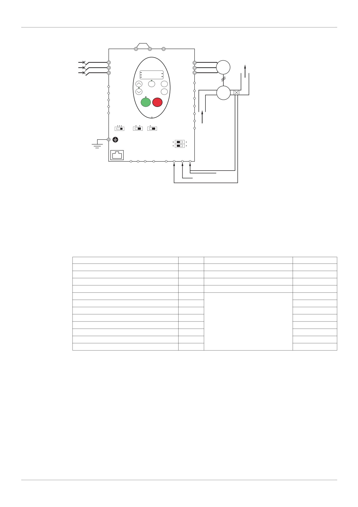
Setpoint 0 - 10 V
Feedback mA or voltage signal
1. Wire analog inputs as indicated in the above figure.
2. Set switch SW102 to source.
3. If the feedback is a milliamp signal, set switch SW100 to the I (current) position. If the feedback is a voltage
signal, set switch SW100 to the V (voltage) position.
4. Program common parameters of ATV212 (see Quick Menu page 59).
5. Program specific parameters for PID control as indicated in the following table:
Parameter
Page
Setting
Factory value
FMOd [Frequency mode sel]
87
2 [Communication]
1
F109 [VIA selection]
100
0 [AI]
0
F200 [Auto/man speed ref]
118
0 [Enable]
0
F360 [PID control enable]
120
1 [PID by VIA]
0
F359 [PID ctrl wait time]
121
0 s
F362 [PID Prop Gain]
120
0.30 %
F363 [PID Integral Gain]
120
0.20
In accordance
F366 [PID Derivative Gain]
121
0.00
with the
F380 [PID reverse error]
121
0
application
F391 [Stop on LL hyst]
122
0.2 Hz
F392 [PID wake up (thres)]
122
0.0 Hz
F393 [PID wake up, feedb]
122
0.0 Hz
48
Overview
Drive Operation
Local and Remote Modes of Operation
Overview
The ATV212 drive has two modes of operation, local and remote.
In local mode, the ATV212 drive can be operated only from the embedded display terminal or graphic display
option:
Use the RUN and STOP keys for command control
Use the UP and DOWN keys for speed control
In remote mode, the ATV212 drive is operated from a combination of the command and speed reference sources
defined by programming parameters [Frequency mode sel] (FMOd) and [Command mode sel] (CMOd) (see
page 87).
Command Sources
The command source [Command mode sel] (CMOd) choices are:
External signals to the control terminal logic inputs F, R, RES and VIA
Serial communication control (Modbus®, Metasys® N2, Apogee® FLN P1, BACnet, or LonWorks®)
Embedded display terminal RUN and STOP keys or graphic display option
Speed Reference Sources
The speed reference source [Frequency mode sel] (FMOd) choices are:
External signals to the control terminal analog inputs VIA or VIB
(4-20 mA, 0-10 Vdc),
External signals to the control terminal logic inputs assigned to +/- Speed
Serial communication control (Modbus®, Metasys® N2, Apogee FLN P1®, BACnet, or LonWorks®)
Embedded display terminal UP and DOWN keys or graphic display option
49
Overview
Command Mode Selection and Priorities
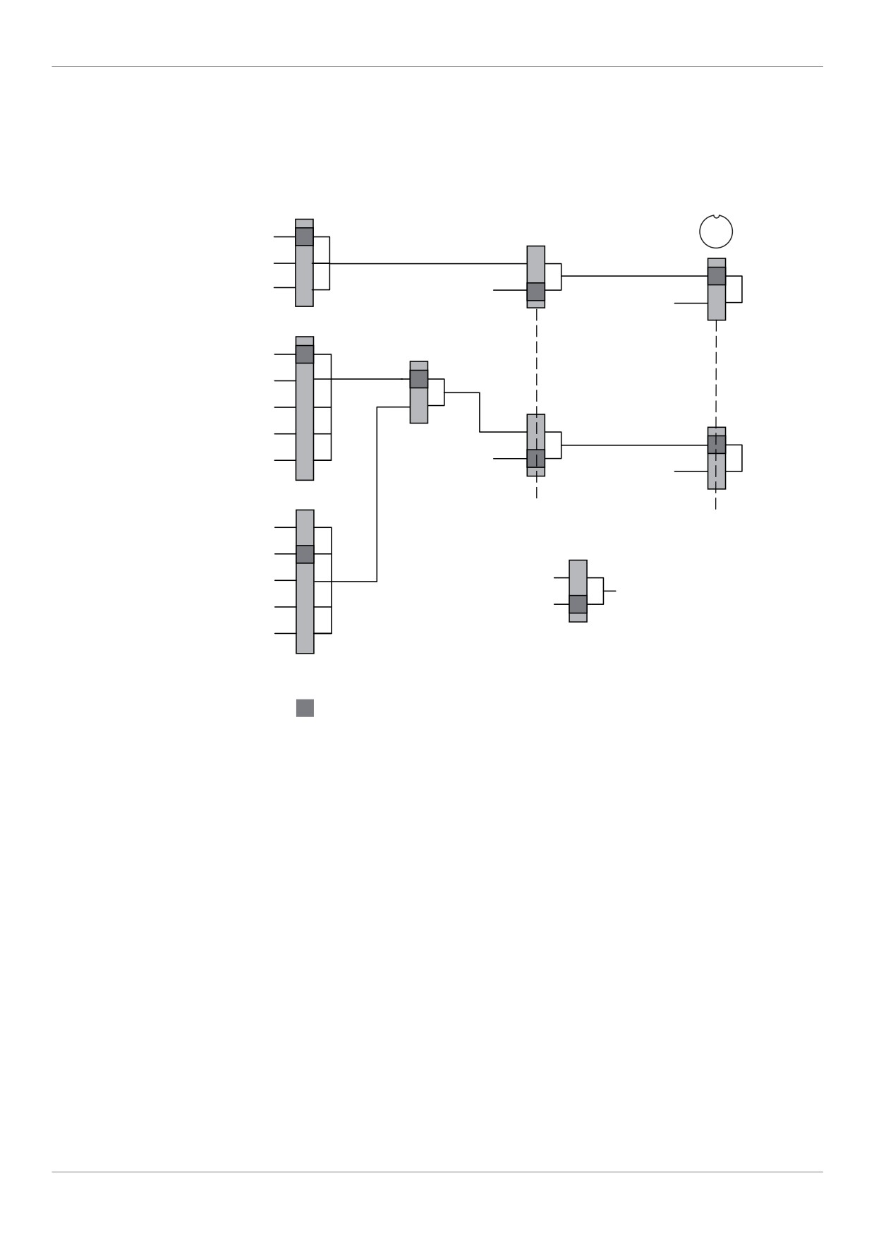
The diagram below illustrates the control inputs and selection logic which determine the source of the drive's
start/stop and speed reference commands.
Command and Reference Switching
Commands
CMOd
Forced Local
LOC
Logic inputs
0
{LIx = 48}
REM
Terminal Local
1
ON
Graphic display
REM
option
2
OFF
Cmd
Communication
Communication
LOC
SetPoint
Terminal Local
Graphic display
References
option
FMOd
Switching
FMOd / F207
1
VIA
{LIx = 38 or F200}
active
2
VIB
Terminal Local
inactive
3
Graphic display
option
ON
4
Communication
REM
5
OFF
Speed
Up/Down speed
Communication
LOC
SetPoint
Terminal Local
Graphic display option
F207
1
VIA
VIB
2
F807
Terminal Local
3
RJ45 channel: Modbus
Graphic display
option
Communication
Network channel:
4
Communication
Paremeter F829
5
Up/Down speed
Default value
Parameters [Command mode sel] (CMOd) and [Frequency mode sel] (FMOd) are the first layers of logic used
by the drive to determine its command CMOd and speed reference FMOd source.
[Remote spd ref 2] (F207) is a secondary speed reference source that may override the source selected by
FMOd (see page 87).
The speed reference source identified by F207 takes control if either:
A logic input assigned to function 38 (frequency reference source switching) is enabled, or
Parameter [Auto/man speed ref] (F200) is set to 1 and the drive's output frequency is equal to or less than
1 Hz (see page 118).
If a serial communication link is established, it can take control of the ATV212 drive, overriding inputs identified
by CMOd, FMOd, and F207. Control is restored to CMOd, FMOd, and F207 only if:
The serial communication link relinquishes control, or
A logic input assigned to function 48 (forced local) is enabled.
The final layer of logic used by the drive to determine its command source is the LOC/REM key on the graphic
display option.
When the drive and embedded HMI is set to local mode (by pressing the LOC/REM key, lighting the local mode
LED), the drive responds only to commands from the embedded and graphic display option.
50
Overview
Selecting Local or Remote mode
DANGER
UNINTENDED EQUIPMENT OPERATION
Know the state of the frequency and run commands from the remote source before exiting the local mode.
Upon entering the remote mode, the drive will respond to the most recent command from the remote source,
even if it was received before entering or while in the local mode.
Failure to follow these instructions will result in death or serious injury.
Switching between local and remote mode is achieved with the LOC/REM key on the drive’s embedded display
terminal or with F4 key on the graphic display option.
The LOC/REM key can be disabled by setting parameter [Loc/rem key] (F732) to 1 (see page 90).
When parameter [Switch rem/Local] (F295) is set to 1 (factory setting), a bumpless tranfer of motor operation
is achieved when switching from remote to local mode (see page 88).
For example, if the bumpless transfert feature is active and if the motor is running at full speed with the drive in
remote mode, the motor will still run at full speed after the drive is transferred to local mode.
Conversely, when switching from local to remote mode, the run and speed command is not transferred to the
remote mode. Upon entering the remote mode, the drive will operate on the run and speed command set by the
remote source even if it was received before entering or while in the local mode.
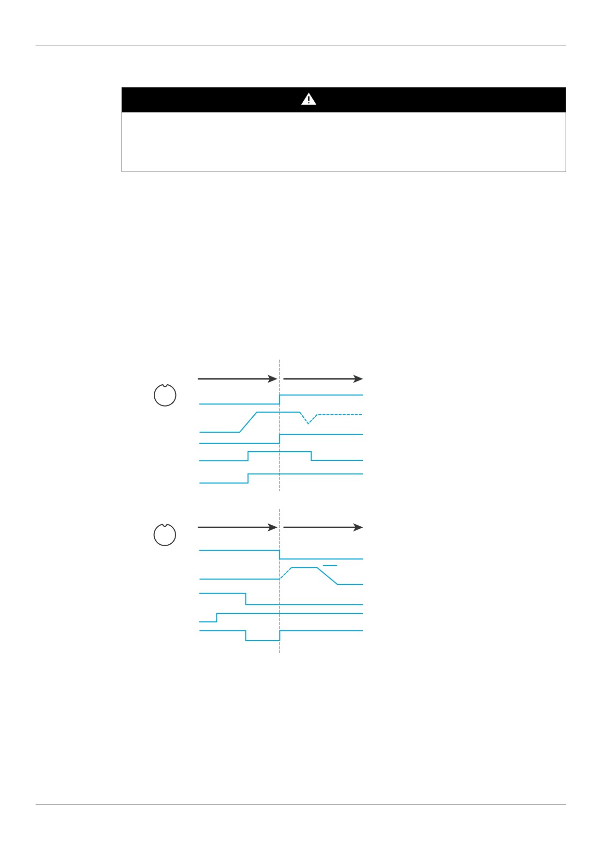
The diagram below is an example timing diagram.
Switching Between Local and Remote Mode
Remote mode
Local mode
The remote run command and
ON
LOC
frequency command are transferred
ey
REM K
OFF
to the local mode when the
LOC/REM key is pressed.
Output Frequency
In this example, the run command
Local Run Command
and frequency command from
the remote mode are copied to
Remote Run Command
ON
the local mode, and the motor
OFF
continues to run.
Run Status
Local mode
Remote mode
When switching from the local
LOC Key ON
REM
mode to the remote mode, the run
OFF
command and frequency
command are determined by
Set frequency
the setting in the remote mode.
Output Frequency
at remote mode
Local Run Command
In this example, when the
LOC/REM button is pressed, the
motor in started.
Remote Run Command
This is due to the application of a
Run Status
ON
remote run command when
OFF
the drive exits the local mode and
enters the remote mode.
51
Overview
Local Mode
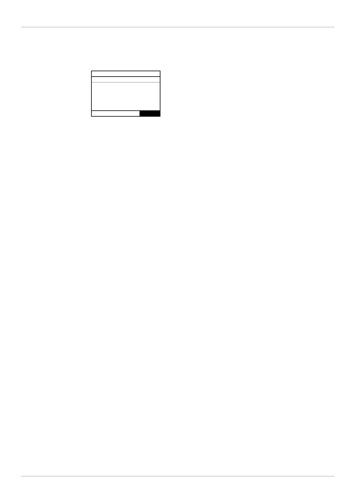
When the ATV212 drive is in local mode, the LED above the LOC/REM key is illuminated.
On the graphic display option:
AUF: QUICK MENU
LL: Low Limit frequency
DEC: Deceleration time 1
ACC: Acceleration time 1
AU1: Auto ramp
vLv: Motor rated voltage
Loc Ref loc Cmd loc Loc/Rem
Starting and Stopping the Motor in Local Mode
Start and stop the motor with the RUN and STOP keys on the graphic/embeded display terminals.
The setting of parameter [Loc. mot stop mode] (F721) determines how the motor stops when the drive is in
local mode (see page 88):
If F721 is set to 0 (factory setting), the motor will stop on a ramp, based on the time value set in parameter
[Deceleration time 1] (dEC) or parameter [Deceleration time 2] (F501).
If F721 is set to 1, power will be removed from the motor when the STOP key is pressed, allowing the motor
to coast to a stop with the ramp-down time determined by inertia and friction.
Use of the RUN and STOP keys in local mode can be disabled using parameter [Run/stop key] (F733) (see
page 90).
Adjusting Motor Speed in Local Mode
Set the motor speed using the UP and DOWN keys on the graphic/embeded display terminals. Motor speed can
be adjusted while the drive is operating.
Normally, motor frequency changes by 0.1 Hz each time the UP or DOWN key is pressed. This rate of speed
change can be altered by entering a new frequency step change into parameter [Loc. speed ref. step] (F707)
(see page 87).
If the ENT key is pressed after the motor speed has been adjusted, that speed setpoint value will be entered into
parameter FC. The next time the drive is Power ON in local mode, it will accelerate the motor directly to the
speed setpoint memorized by [Local speed ref.] (FC) (see page 87).
Selecting Motor Rotation Direction in Local Mode
Motor rotation direction is set by parameter [Local mot. direction] (Fr) (see page 87). The four selections are:
0: Forward only (factory setting)
1: Reverse only
2: Forward, with reverse selectable from the graphic/embeded display terminals (1)
3: Reverse, with forward selectable from the graphic/embeded display terminals (1)
(1)If Fr is set to either 2 or 3, motor rotation can be set to forward by pressing the UP key while holding the
ENT key. Reverse can be set by pressing the DOWN key while holding the ENT key.
Motor rotation is indicated on the embedded display terminal as Fr-F for forward and as Fr-r for reverse.
The ability to run in the Forward or Reverse direction can be set with parameter [Motor direction] (F311) (see
page 96).
52
Overview
Resetting drive detected fault in Local Mode
It is not possible to clear a drive detected fault if the cause of the detected fault persists. Be certain to diagnose
and rectify the cause of the detected fault before attempting a drive reset.
With the STOP Key
To clear a drive detected fault in local mode:
1. Press the STOP key. See Fault detection codes that can be cleared with the automatic restart function after
the cause has disappeared on page 135 for a list of detected faults that can be cleared with the STOP key. If it
is possible to reset the drive, the embedded display terminal will display CLr.
2. To clear the detected fault, press the STOP key a second time.
3. If the cause of the detected fault is still present, the CLr display will not appear. Diagnose and clear the
detected fault before attempting to reset the drive.
Use of the STOP key as a clear detected fault can be set with parameter [HMI reset button] (F735) (see page
90).
In the event of an OL1 or OL2 detected fault, the following time periods are necessary before a clear detected
fault is possible:
OL1 (drive overload)—about 30 seconds after the detected fault has occured
OL2 (motor overload)—about 120 seconds after the detected fault has occured
By Cycling Line Power
A drive detected fault can also be cleared by removing and restoring line power. Be certain that the cause of the
detected fault is no longer present and leave power removed long enough for all of the LEDs on the face of the
drive to extinguish.
Cycling power to clear a detected fault can cause the detected fault history to be lost. Refer to parameter [Drive
Fault Memory] (F602) on page 138.
Logic Input Functions Active in Local Mode
The logic input functions listed in the table below are active, even if [Command mode sel] (CMOd) is set to 1
(embedded display terminal control). See table on page 100 for logic input function settings.
Logic Input
Description
Function No.
1
[Run permissive]
54
[Inverse Run permissive]
10
[Fault reset]
55
[Inv fault reset]
11
[Ext Fault]
45
[Inv Ext. fault]
16
[Run reset]
38
[Frequency source]
41
[(+) speed]
42
[(-) speed]
43
[+/- clear]
44
[+/- SPD, FLT CLR]
46
[Ext. Th fault]
47
[Inv Ext. Th fault]
51
[Reset kWh]
52
[Forced mode]
53
[Fire mode]
62
[RY on]
64
[Cancel HMI cmd]
53
Overview
Remote Mode
When the ATV212 drive is in the remote mode, the LOC/REM LED is off.
Starting and Stopping the Motor in Remote Mode
The diagram on page 50 illustrates the start/stop command source when the drive is in remote mode.
With Logic Input Terminals
Use the logic input terminals F, R, RES, or VIA to start the drive if parameter [Command mode sel] (CMOd) is
set to [Logic Inputs] (0) (factory setting).
With the display terminals
The drive responds to commands from the embedded display terminal or graphic display option, just as in local
mode, if parameter [Command mode sel] (CMOd) is set to [HMI] (1).
With Serial Communication
The drive responds to commands sent over the serial communication link (Modbus®, Metasys® N2, Apogee®
FLN, BACnet or LonWorks®) if parameter [Command mode sel] (CMOd) is set to [Communication] (2).
The drive responds to commands sent over the RJ45 communication port if parameter [Com channel choice]
(F807) is set to 0. Other protocols are available when F807 is set to 1 on open style port.
With the graphic/embeded display terminals STOP Key
The graphic/embeded display terminals STOP key is active when the drive is in remote mode. Pressing the
STOP key causes the drive to stop according to the setting of parameters [Ext. fault stop Mode] (F603), [DC
brk time ext flt] (F604), and [DC braking current] (F251) (see page 126 and page 98) . After the drive has
come to a stop, the graphic/embeded display terminals display E and the fault relay is activated.
Adjusting the Motor Speed in Remote Mode
The diagram on page 50 illustrates the speed reference source when the drive is in remote mode.
By Analog Input VIA
A 0-10 Vdc or 4-20 mA signal connected to VIA and CC can be used to adjust the motor speed if:
Parameter [Frequency mode sel] (FMOd) is set to 1 (factory setting).
Alternate speed reference source parameter [Remote spd ref 2] (F207) has not been enabled (see page
88).
The analog signal type depends on the setting of switch SW100 and parameters F109, F201-F204, and
F470-F471.
By Analog Input VIB
A 0-10 Vdc signal connected to VIB and CC can be used to adjust the motor speed if:
Parameter [Frequency mode sel] (FMOd) is set to 2.
Alternate speed reference source parameter [Remote spd ref 2] (F207) has not been enabled.
The control that VIB has over motor speed depends on the setting of switch SW100 and parameters
F210-F213, F472-F473, and F645.
54
Overview
By display terminal Control
Control of the motor speed is enabled, if:
Parameter [Frequency mode sel] (FMOd) is set to 3.
Alternate speed reference source parameter [Remote spd ref 2] (F207) has not been enabled.
By Serial communication control
Serial communication control (Modbus, Metasys N2, Apogee FLN, BACnet or LonWorks) of the motor speed is
enabled, if:
Parameter [Com channel choice] (F807) is set to 0 (only for Modbus on RJ45 port),
Parameter [Com channel choice] (F807) is set to 1,
Parameter [Frequency mode sel] (FMOd) is set to 4.
Alternate speed reference source parameter [Remote spd ref 2] (F207) has not been enabled.
By +/- Motor Speed Control
+/- Motor speed control is enabled, if:
Parameter [Frequency mode sel] (FMOd) is set to 5,
Alternate speed reference source parameter [Remote spd ref 2] (F207) has not been enabled.
Selecting Motor Rotation Direction in Remote Mode
The diagram on page 50 illustrates the motor rotation command source when the drive is in remote mode.
With Logic Input Terminals
Use the logic input terminals F, R, RES, or VIA to select motor rotation direction if parameter [Command mode
sel] (CMOd) is set to 0 (factory setting).
With the embedded display terminal or graphic display option
Motor rotation direction can be set by pressing the display terminal UP and ENT keys if:
Parameter [Command mode sel] (CMOd) is set to 1,
Serial communication control has not been established.
Parameter [Local mot. direction] (Fr) is set to either 2 or 3.
With Serial Communication
The drive responds to commands sent over the serial communication link (Modbus, Metasys N2, Apogee FLN,
BACnet or LonWorks) if Parameter [Command mode sel] (CMOd) is set to 2.
Resetting drive detected faults in Remote Mode
The diagram on page 50 illustrates the clear detected fault command source when the drive is in remote mode.
It is not possible to clear a drive detected fault if the cause of the detected fault persists. Be certain to diagnose
and rectify the cause of the detected fault before attempting to reset the drive.
See Automatically Resettable detected faults on page 135 for a list of detected faults that can be cleared in
remote mode.
With the Logic Input Terminals
Use the logic input terminals F, R, RES, or VIA to clear a drive detected fault if parameter [Command mode sel]
(CMOd) is set to 0 (factory setting).
With the graphic/embeded display terminals
The STOP key can be used to clear a drive detected fault if parameter [Command mode sel] (CMOd) is set to 1.
To clear a drive detected fault, press the STOP key. If it is possible to reset the drive, it will display CLr. To
clear the detected fault, press the STOP key a second time.
If the cause of the interruption is still present, the CLr display will not appear. Diagnose and clear the detected
fault before attempting to reset the drive.
The use of the STOP key as a clear detected fault can be managed by parameter [HMI reset button] (F735).
55
Overview
With Serial Communication
A drive detected fault can be cleared over the serial communication link (Modbus, Metasys N2, Apogee FLN,
BACnet or LonWorks) if parameter [Command mode sel] (CMOd) is set to 2.
In the event of an OL1 or OL2 detected fault, the following time periods needs to pass before a clear detected
fault is possible:
OL1 (drive overload) - about 30 seconds after the occurrence of the event.
OL2 (motor overload) - about 120 seconds after the occurrence of the event.
By Cycling Line Power
A drive detected fault can also be cleared by removing and restoring line power. Be certain that the cause of the
detected fault is no longer present and leave power removed long enough for all of the LEDs on the face of the
drive to go out.
Cycling power to clear a detected fault can cause the detected fault history to be lost. Refer to parameter F602
on page 138 for drive fault memory options.
56
Programming
Programming
II
What's in this Part?
This part contains the following chapters:
Chapter
Chapter Name
Page
3
Quick Menu
59
4
Programming Parameters
65
5
Motor Control Parameters
69
6
Drive Control Parameters
87
7
Application Parameters
91
8
I/O Control Parameters
99
9
Display Parameters
129
10
Detected Fault Management Parameters
133
11
Serial Communication Parameters
147
12
Start/Stop Control By Speed Reference Level
153
13
Droop Control
155
57
Programming
58
Quick Menu
Quick Menu
3
What's in this Chapter?
This chapter contains the following topics:
Topic
Page
Quick menu
60
59
Quick Menu
Quick menu
The AUF submenu provides ready access to the ten basic parameters commonly used in programming the
drive.
In many cases, programming the ATV212 drive is complete when these 10 parameters and motor parameters
have been properly set. .
Code
Name / Description
Adjustment range
Factory setting
AU1
[Auto ramp]
Automatic ramp adaptation
-
1
0
[Disabled]
1
[Enable]: [Acceleration time 1] (ACC) and [Deceleration time 1] (dEC)
2
[ACC only]: [Acceleration time 1] (ACC) only
If parameter AU1 is set to 1 or 2, the drive will monitor its own loading level and optimize the acceleration and deceleration
ramps. The acceleration and deceleration AU1 = 1 only rates will be automatically adjusted between 1/8 to 8 times the settings
of ACC and dEC, depending on the drive’s current rating and the load level on the motor. ACC and dEC should be appro-
priately set for an average load in the application. If the load on the motor increases rapidly during ramp up or ramp down, the
auto ramp adaptation feature may not help to prevent the drive from experiencing an overcurrent or overvoltage.
If the application requires a consistent acceleration and deceleration time, set AU1 to 0, and set ACC and dEC manually as
needed. The manual acceleration and deceleration times can still be overridden by the [Motor Current Limit] (F601) (see page
73) and [Overvoltage fault] (F305) (see page 139) and [Overvoltage level] (F626) (see page 139) functions.
ACC
[Acceleration time 1]
0.0 to 3200 s
According to drive
rating (1)
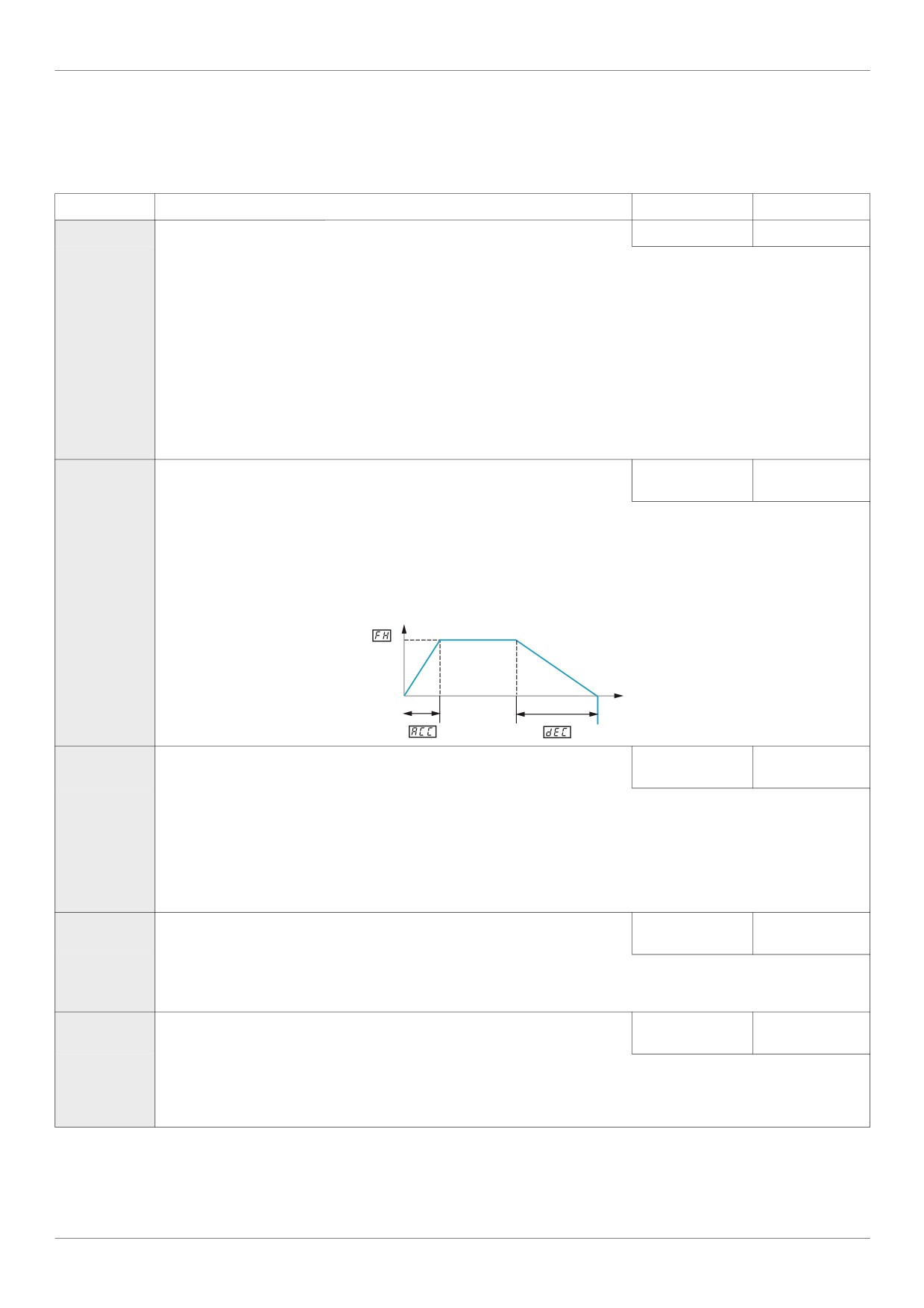
The setting of parameter ACC determines the slope of the acceleration ramp and the time it takes for the output frequency of the
drive to increase from 0 Hz to the setting of [Max frequency] (FH) (see page 92).
If parameter [Auto ramp] (AU1) is set to 1 or 2, the acceleration ramp may be increased or decreased from the setting of ACC,
depending on the amount of load on the motor during ramp up.
If two different acceleration rates are needed, see parameter [Acceleration time 2] (F500) on page 93.
Output frequency (Hz)
0
Time (s)
dEC
[Deceleration time 1]
0.0 to 3200 s
According to drive
rating (1)
The setting of parameter dEC determines the slope of the deceleration ramp and the time it takes for the output frequency of
the drive to decrease from the setting of [Max frequency] (FH) to 0 Hz.
If parameter [Auto ramp] (AU1) is set to 1 or 2, the deceleration ramp may be increased or decreased from the setting of dEC,
depending on the amount of load on the motor during ramp down. See diagram above.
If two different deceleration rates are needed, see parameter [Deceleration time 2] (F501) on page 93.
LL
[Low limit frequency]
0.0 to [Upper limit
0.0 Hz
freq] (UL) Hz
If [Driving Scroll] (F324) page 160 is set to [yes] (1) the setting is replaced by 30%.
Parameter LL sets the minimum frequency that can be commanded to the drive by the local or remote speed reference source.
UL
[Upper limit freq]
0.5 to [Max fre-
50.0 Hz
quency] (FH) Hz
If [Driving Scroll] (F324) page 160 is set to [yes] (1) the setting is replaced by 90%.
Parameter UL sets the maximum frequency that can be commanded to the drive by the local or remote speed reference source.
The top end of its range is limited by the setting of [Max frequency] (FH).
(1) See table page 199
60
Quick Menu
Code
Name / Description
Adjustment range
Factory setting
tHr
[Motor thermal prot.] Motor Rated Current Overload Setting
10 to 100% of the
100%
drive’s output cur-
rent rating
Set parameter tHr to the motor’s rated current as indicated on the motor nameplate for the selected operating voltage.
If parameter [Unit value selection] (F701) is set to 1 (see page 130), parameter tHr will be adjusted in amperes.
If parameter F701 is set to 0, parameter tHr will be adjusted in percentage. In this case, divide the motor rated current by
the drive rated current (as listed on its nameplate) and set parameter tHr to the resulting percentage.
The setting of parameter [Switch. freq. level] (F300) does not change the drive’s rated current for the sake of this calculation
(see page 95).
FM
[AO scaling]
Analog output scaling
-
Parameter FM is used to match the FM terminal output signal with the input requirements of the attached panel meter by adjusting
the slope and bias of the analog output signal. Before adjusting FM, set FMSL to either 15 or 17. As you adjust the value of
FM, monitor the display on the attached panel meter. When the meter display reaches 100%, press the ENT key on the drive
display terminal. The drive will flash between FM and the adjusted value, indicating that the adjustment has been saved.
Pt
[Mot cont. mode sel.] Motor control mode
1
If [Driving Scroll] (F324) page 160 is set to [yes] (1) the setting is replaced by [SVC] (3).
0
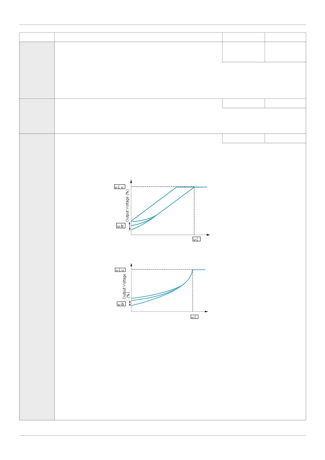
[Constant V/Hz]: Constant V/Hz
Use constant V/Hz mode for loads that require the same torque at low speeds as at rated speeds. Low speed torque can be ad-
justed manually by setting parameter [Motor Voltage Boost] (ub) (see page 73).
Motor rated voltage
Motor Voltage Boost
Output Frequency (Hz)
0
Motor Rated Frequency
1
[Variable Torque]: Variable torque
Use variable torque mode for loads such as centrifugal fans and pumps whose torque requirements increase as a square of the
increase in motor speed. Low speed torque can be adjusted manually by setting parameter ub.
Motor rated voltage
Motor Voltage Boost
0
Output Frequency (Hz)
Motor Rated Frequency
2
[Cst V/Hz+Boost]: Constant V/Hz with automatic torque boost
See the diagram on page 70.
This mode is similar to the constant V/Hz mode (for loads that require the same torque at low speeds as at rated speeds), except
it automatically increases motor voltage and torque to compensate for increases in load.
3
[SVC]: Sensorless vector control
Use sensorless vector control mode to increase torque at motor speeds below 3 Hz or to improve speed regulation (0.5 to 1%).
See diagram on page 70.
4
[Economy]: Energy saving
In energy savings mode, the ATV212 drive monitors motor loading and automatically modulates the voltage applied to the motor
to optimize energy consumption.
If the ATV212 drive and the connected motor have the same power rating, and if the motor has a nominal 1500 rpm rating, no
motor auto-tuning is required to use this motor control mode. Otherwise, follow the steps outlined in “Motor Tuning” on page 74.
5
[Do not use]: Reserved
6
[PM Control]: Permanent magnet
61

Quick Menu
Code
Name / Description
Adjustment range
Factory setting
uL
[Motor rated freq.]
Motor rated frequency
25.0 to 400.0 Hz
50.0 Hz
Set parameter uL (vL) to the motor’s rated frequency as indicated on the motor nameplate.
Note: It is possible to set the drive’s various motor control frequencies to 50 Hz by setting [Parameter reset] (tYP) to 1, the 50
Hz reset. For more information, see page 66.
uLu
[Motor rated voltage]
According to drive
According to drive
rating
rating (1)
Set parameter uLu (vLv) to the motor’s rated voltage as indicated on the motor nameplate.
ATV212pppM3X: 50 to 330 V.
ATV212pppN4: 50 to 660 V
Note: Drive output voltage cannot be set to exceed the input line voltage level.
(1) See table page 199
62
Quick Menu
Motor parameters
Configure the motor parameters and perform an auto-tuning ([Auto-tuning drive] (F400) = 2, see page 75 for
auto-tuning).
Code
Name / Description
Adjustment range
Factory setting
F415
[Motor rated current] Motor rated full load current
0.1 to 200.0 A
According to drive
rating (1)
Set parameter F415 to the motor rated full load current in amperes as indicated on the motor’s nameplate.
F417
[Motor rated speed]
100 to 15000 rpm
According to drive
rating (1)
Set parameter F417 to the motor rated speed in rpm as indicated on the motor’s nameplate.
F601
[Motor Current Limit]
10 to 110% of the
110%
drive’s output cur-
rent rating
NOTICE
RISK OF DAMAGE TO THE MOTOR AND THE DRIVE
Check that the motor will withstand this current.
Check that the profile mission complies with the derating curve given in the installation manual
Failure to follow this instruction can result in equipment damage.
Parameter F601 can be adjusted to limit current during motoring or braking.
Display in Current Limit Mode:
When the drive goes into current limit mode, it will:
Adjust the output frequency to limit the flow of motor current (down when motoring, up when braking).
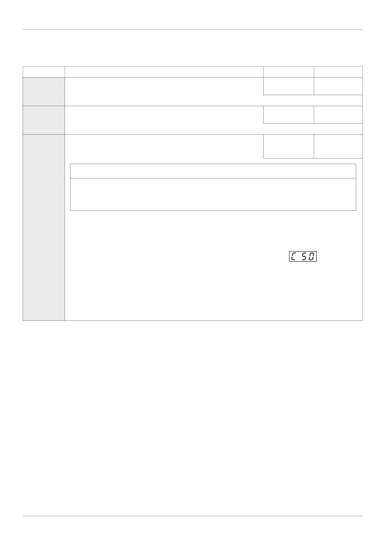
Display the letter C and the output frequency flashing on the embedded software terminal, ex:
If parameter [Unit value selection] (F701) is set to 1 (see page 130), parameter F601 will be adjusted in amperes. If param-
eter F701 is set to 0, parameter F601 will be adjusted as a percentage of the drive’s output rated current as listed on its
nameplate.
The setting of parameter [Switch. freq. level] (F300)
(see page 95) does not change the drive’s rated current for the sake of
this calculation.
Do not set parameter F601 below the no-load current rating of the motor.
(1) See table page 200.
63
Quick Menu
Code
Name / Description
Adjustment range
Factory setting
F400
[Auto-tuning drive] Auto tuning enable
-
0
DANGER
HAZARD OF ELECTRIC SHOCK OR ARC FLASH
During auto-tuning, the motor operates at rated current.
Do not service the motor during auto-tuning.
Failure to follow these instructions will result in death or serious injury.
WARNING
LOSS OF CONTROL
It is essential that the following parameters uLu, uL, F415 and F417 are correctly configured before starting auto-
tuning.
When one or more of these parameters have been changed after auto-tuning has been performed, F400 will return 0
and the procedure will have to be repeated.
Failure to follow these instructions can result in death or serious injury.
NOTICE
RISK OF DAMAGE TO THE MOTOR
Conduct auto-tuning only after the motor has been connected and operation completely stopped.
If auto-tuning is conducted immediately after operation stops, the presence of a residual voltage may result in abnormal
tuning.
Failure to follow these instructions can result in equipment damage.
0
[Disabled]: Disabled
1
[Initialize constant]:
Factory setting of [Auto Torque Boost] (F402) for asynchronous motor.
Factory setting of [Auto Torque Boost] (F402) , [Autotune L q-axis] (F912), and [Autotune L d-axis] (F913), and
[Motor Rated Voltage] (vlv) for synchronous motor.
2
[Tun Dyn. 1]:Tune Dynamic, with driving run after the tuning.
Application settings of [Auto Torque Boost] (F402) for asynchronous motor.
Application settings of [Auto Torque Boost] (F402) , [Autotune L q-axis] (F912), and [Autotune L d-axis] (F913) for
synchronous motor.
3
[Tun Dyn. 2]: Complete tune Dynamic, with driving run after the tuning.
Application settings of [Auto Torque Boost] (F402) , [Autotune L q-axis] (F912), [Autotune L d-axis] (F913), and
[Motor Rated Voltage] (vlv) for synchronous motor.
4
[Tun Static 1]: Tune Static, without driving run after the tuning.
Application settings of [Auto Torque Boost] (F402) for asynchronous motor.
Application settings of [Auto Torque Boost] (F402) , [Autotune L q-axis] (F912), and [Autotune L d-axis] (F913) for
synchronous motor.
5
[Tun Static 2]: Complete tune Static, without driving run after the tuning.
Application settings of [Auto Torque Boost] (F402) , [Autotune L q-axis] (F912), and [Autotune L d-axis] (F913), and
[Motor Rated Voltage] (vlv) for synchronous motor.
Parameter F400 is reset to “0” after the auto tuning is performed.
64
Programming Parameters
Programming Parameters
4
What's in this Chapter?
This chapter contains the following topics:
Topic
Page
Parameter Reset
66
Macro Programming (AU4)
67
Parameter Lock
68
Display of Submenu AUF (F738)
68
65
Programming Parameters
Parameter Reset
Parameter Reset Options
The ATV212 drive offers three options to return parameters to their factory default settings:
Factory reset: set parameter [Parameter reset] (tYP) to 3
50 Hz reset: set parameter [Parameter reset] (tYP) to 1
60 Hz reset: set parameter [Parameter reset] (tYP) to 2
Code
Name / Description
Factory
setting
tYP
[Parameter reset]
0
DANGER
UNINTENDED EQUIPMENT OPERATION
When tYP is set to 3 or 8:
- Check that the modification of the current configuration is compatible with the wiring diagram used.
- All logic inputs must be deactivated to avoid unintended restart.
Failure to follow these instructions will result in death or serious injury.
0
[No action]
1
[50 Hz reset]: 50 Hz parameter reset
Setting parameter tYP to a value of 1 will set specific parameters to values suitable for many 50 Hz (motor base frequency) ap-
plications.
See Parameters whose values after a reset vary by reset type table on page 198 and table on page 200 for a list of parameters that
are affected by this reset action and their resultant values.
2
[60 Hz reset]: 60 Hz parameter reset
Setting parameter tYP to 2 sets specific parameters to values suitable for many 60 Hz (motor base frequency) applications. See
table "Parameters whose values after a reset vary by reset type" on page 198 and table "Parameters whose values after a reset
are drive model dependant but do not vary by reset type" on page 199 for a list of parameters that are affected by this reset action
and their resultant values.
3
[Factory set]: Factory reset
Setting parameter tYP to 3 resets most parameters to their factory settings. See tables listed below for a listing of the values that
will be copied into the drive by this factory reset action:
Parameters whose values after a reset do not vary by reset type (on page 194).
Parameters whose values after a reset vary by reset type (on page 198).
Parameters whose values after a reset are drive model dependant but do not vary reset type (on page 199).
Parameters whose values after a reset are drive model and reset type dependant (on page 200).
Parameters whose values do not change if a reset is performed (on page 201).
A factory reset will also clear the detected fault history.
4
[Trip cleared]: detected fault history cleared
Setting parameter tYP to 4 clears the detected fault history. As soon as the detected fault history is reset, parameter tYP re-
sumes its default value of 0.
5
[Cumul time clear]: Elapsed Motor Run Time Reset
Setting parameter tYP to 5 resets the elapsed motor run time clock. As soon as the elapsed motor run time clock is reset, pa-
rameter tYP resumes its default value of 0.
6
[EtYP fault reset]: Clear EtYP detected fault
Setting parameter tYP to 6 clears a EtYP detected fault. As soon as the EtYP detected fault is cleared, parameter tYP
resumes its default value of 0.
7
[Save parameters]: Save user-defined settings
The drive parameter settings can be stored into memory into the drive as a custom parameter set.
Set parameter tYP to 7 to save the current drive parameter settings to memory
8
[Recall parameters]: Recalls user-defined settings
The drive parameter settings can be reloaded into the drive as a custom parameter set.
Set parameter tYP to 8 to reload into the drive the parameter settings last saved by setting tYP to 7.
9
[Elapse time reset]: Elapsed drive run time reset
Setting parameter tYP to 9 resets the elapsed drive run time clock. As soon as the elapsed motor run time clock is reset, param-
eter tYP resumes its default value of 0.
66
Programming Parameters
Macro Programming (AU4)
The ATV212 drive can be configured for four common control schemes by setting parameter AU4:
Code
Name / Description
Factory setting
AU4
[Auto set function]
Macro Programming (1)
0
DANGER
UNINTENDED EQUIPMENT OPERATION
Check that the selected macro configuration is compatible with the wiring diagram used.
Failure to follow these instructions will result in death or serious injury.
0
[Factory set]
Command reference: logic inputs (CMOd = 0). See page 87.
Speed reference: analog input VIA = 0-10 V or 0-20 mA (FMOd = 1, F201 = 0). See [Frequency mode sel] (FMOd) page 87 and
Analog Input Speed Reference page 116.
F: run forward (F111 = 2). See F Logic Input Function page 100.
R: preset speed 1 (F112 = 6). See R Logic Input Function page 100.
RES: clear detected fault (F113 = 10). See RES Logic Input Function page 100.
Drive ready for operation (F110 = 1). See Active Logic Function 2 page 122.
1
[Run permissive]
Command reference: logic inputs (CMOd = 0). See page 87.
Speed reference: analog input VIA = 0-10 V or 0-20 mA (FMOd = 1). See [Frequency mode sel] (FMOd) page 87.
F: run forward (F111 = 2). See F Logic Input Function page 100.
R: run permissive (F112 = 1). See R Logic Input Function page 100.
RES: clear detected fault (F113 = 10). See RES Logic Input Function page 100.
2
[3-wire]
Command reference: logic inputs (CMOd = 0). See page 87.
Speed reference: analog input VIA = 0-10 V or 0-20 mA (FMOd = 1). See See [Frequency mode sel] (FMOd) page 87.
F: run forward (F111 = 2). See F Logic Input Function page 100.
R: stop ramp (F112 = 49). See R Logic Input Function page 100.
RES: clear detected fault (F113 = 10). See RES Logic Input Function page 100.
3
[+/- Speed]
Command reference: logic inputs (CMOd = 0). See page 87.
Speed reference: +/- Speed (FMOd = 5). See See [Frequency mode sel] (FMOd) page 87
F: run forward (F111 = 2). See F Logic Input Function page 100.
R: + Speed (F112 = 41). See R Logic Input Function page 100.
RES: - Speed (F113 = 42). See RES Logic Input Function page 100.
4
[4-20 mA speed ref]
Command reference: logic inputs (CMOd = 0). See page 87.
Speed reference: analog input VIA = 4-20 mA (FMOd = 1, F201 = 20). SeeSee [Frequency mode sel] (FMOd) page 87 and Analog
Input Speed Reference page 116.
F: run forward (F111 = 2). See F Logic Input Function page 100.
R: preset speed 1 (F112 = 6). See R Logic Input Function page 100.
RES: clear detected fault (F113 = 10). See RES Logic Input Function page 100.
(1) When programming parameter AU4, the embedded display terminal will display two numbers. The left number is the value
last entered into AU4. The right number will be 0. Use the UP/DOWN keys to change the right number to the desired value
and press ENT. Entering 0 into AU4 has no effect on the drive. Programming 0 into AU4 will not return the seven
parameters to their factory default values.
67

Programming Parameters
Parameter Lock
Code
Name / Description
Factory setting
F700
[Parameter lock]
0
0
[Unlocked]: All parameters are unlocked and can be changed.
See table on page 41 for the parameters that cannot be changed while the drive is running.
1
[Locked]: Only parameter F700 can be changed.
Display of Submenu AUF (F738)
Code
Name / Description
Factory setting
F738
[Quick menu AUF]
0
The setting of this parameter determines whether the AUF submenu, Quick Menu, will be displayed on the HMI (see page 34).
0
[AUF displayed]: AUF parameter displayed
1
[AUF hidden]: AUF parameter hidden
68
Motor Control Parameters
Motor Control Parameters
5
What's in this Chapter?
This chapter contains the following topics:
Topic
Page
Motor Control Mode
70
Other Motor Control Mode Parameters
72
Motor Tuning
74
Auto-tuning
75
Expert parameters
77
Supply Voltage Correction and Motor Voltage Limitation
78
Motor 2 Control Parameters
79
Permanent Magnet Motor Control Law ([PM Control] (PM))
81
69
Motor Control Parameters
Motor Control Mode
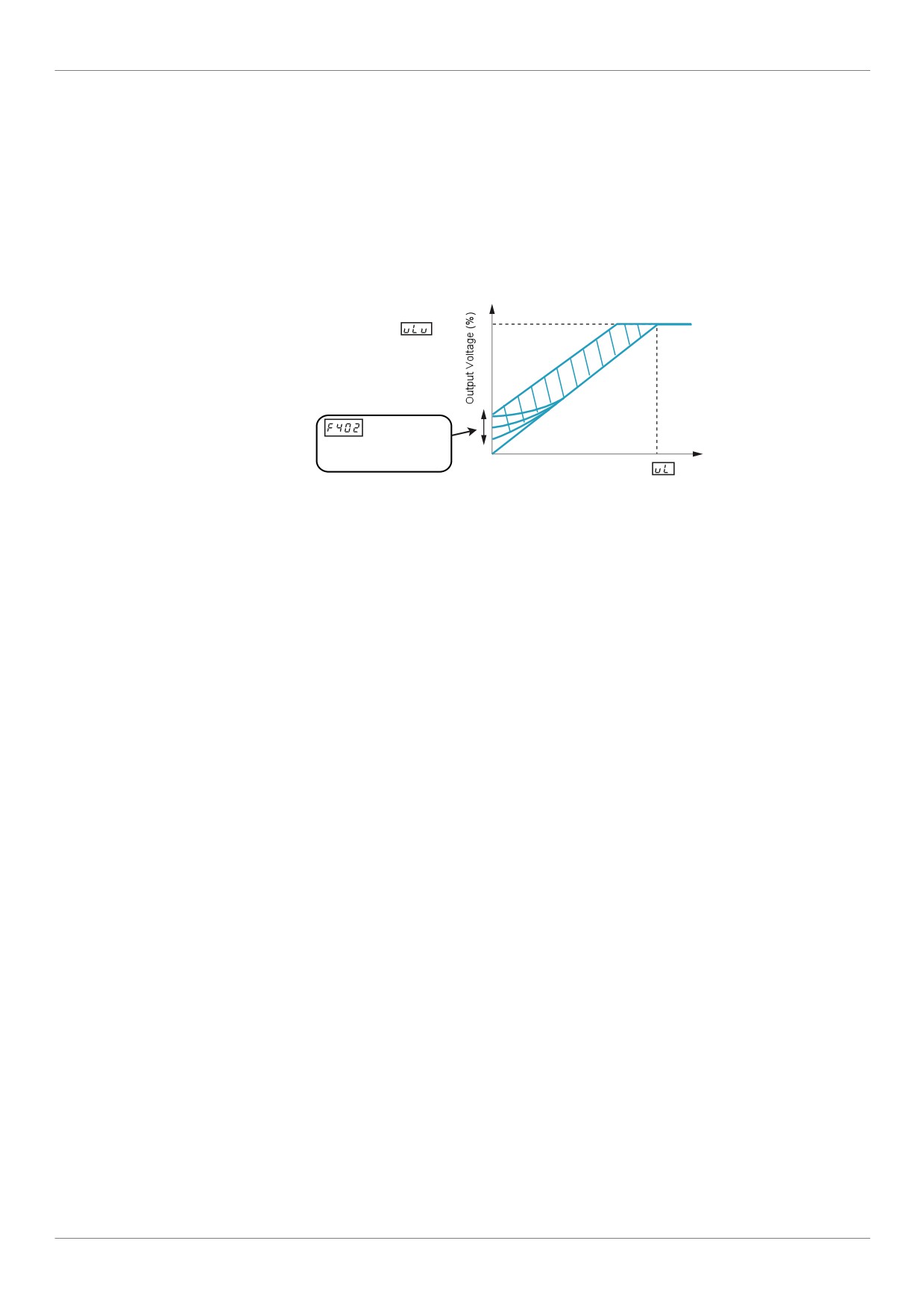
Constant V/Hz Mode with AutomaticTorque Boost ([Mot cont. mode sel.] (Pt) = 2 [Cst V/Hz+Boost])
Use parameter [Auto Torque Boost] (F402) to adjust the amount of automatic torque boost (see page 79).
If the ATV212 drive and the connected motor have the same power rating, and if the motor has a nominal
1500 rpm rating, no motor auto-tuning is required to use this motor control mode. Otherwise, follow the steps
outlined in “Motor Tuning” on page 74.
Due to the feedback circuit used in this mode, it is possible for motor speed to oscillate. If this occurs, select the
Constant V/Hz mode ([Mot cont. mode sel.] (Pt) = 0) and adjust torque boost manually with parameter [Motor
Voltage Boost] (ub).
Motor rated voltage
: Automatically
adjusts the
amount of
0
torque boost.
Motor Rated Frequency
Output Frequency (Hz)
Sensorless Vector Control Mode ([Mot cont. mode sel.] (Pt) = 3 [SVC])
Sensorless vector control mode is only for use in applications where:
Each motor is powered by its own ATV212 drive (not for multi-motor applications).
The motor has a power rating equal to that of the ATV212 drive, or no lower than one hp rating less.
The motor has between two and eight poles (750...3000 rpm).
Sensorless vector control will not improve motor control above the motor’s rated speed.
Sensorless vector control is more effective if the motor leads are less than 30 m (100 ft) in length. If motor leads
longer than 30 m (100 ft) are required, perform an auto-tuning with the long motor leads included in the circuit.
Motor torque may not be maximized at the motor’s rated frequency due to voltage drop in the motor leads.
Connecting a load reactor or a motor filter on the output of the ATV212 drive may reduce the torque generated
by the motor in sensorless vector control mode. Auto-tuning will most likely not be possible with a reactor or filter
attached to the drive. Manual tuning will be required
Permanent Magnet motors Mode ([Mot cont. mode sel.] (Pt) = 6 [PM control])
Permanent magnet motors that are light, small in size, and highly efficient, as compared to induction motors, can
be operated in sensor-less operation mode.
This feature can be used only for specific permanent magnet motors:
- IPM, Interior-buried Permanent Magnet motor.
- SPM, Surface-mounted Permanent Magnet motor.
70
Motor Control Parameters
Code
Name / Description
Factory setting
Pt
[Mot cont. mode sel.] Motor control mode
1
If [Driving Scroll] (F324) page 160 is set to [yes] (1) the setting is replaced by [SVC] (3).
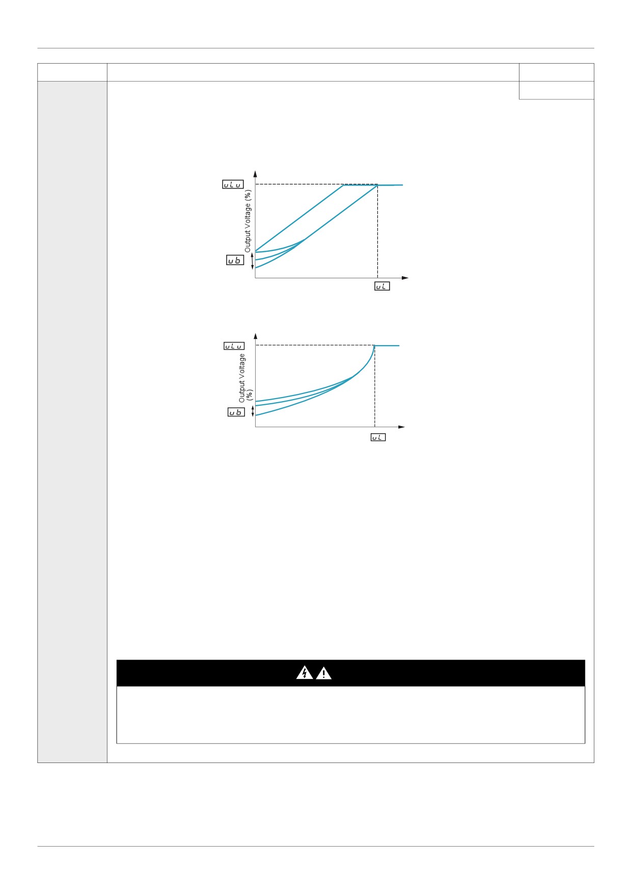
0
[Constant V/Hz]: Constant V/Hz
Use constant V/Hz mode for loads that require the same torque at low speeds as at rated speeds. Low speed torque can be ad-
justed manually by setting parameter [Motor Voltage Boost] (ub) (see page 73).
Motor rated voltage
Motor Voltage Boost
Output Frequency (Hz)
0
Motor Rated Frequency
1
[Variable Torque]: Variable torque
Use variable torque mode for loads such as centrifugal fans and pumps whose torque requirements increase as a square of the
increase in motor speed. Low speed torque can be adjusted manually by setting parameter ub.
Motor rated voltage
Motor Voltage Boost
0
Output Frequency (Hz)
Motor Rated Frequency
2
[Cst V/Hz+Boost]: Constant V/Hz with automatic torque boost
See the diagram on page 70.
This mode is similar to the constant V/Hz mode (for loads that require the same torque at low speeds as at rated speeds), except
it automatically increases motor voltage and torque to compensate for increases in load.
3
[SVC]: Sensorless vector control
See the diagram on page 70.
Use sensorless vector control mode to increase torque at motor speeds below 3 Hz or to improve speed regulation (0.5 to 1%).
4
[Economy]: Energy saving
In energy savings mode, the ATV212 drive monitors motor loading and automatically modulates the voltage applied to the motor
to optimize energy consumption.
If the ATV212 drive and the connected motor have the same power rating, and if the motor has a nominal 1500 rpm rating, no
motor auto-tuning is required to use this motor control mode. Otherwise, follow the steps outlined in “Motor Tuning” on page 74.
5
[Do not use]: Reserved
6
[PM Control]: Permanent Magnet Motor Control Law
DANGER
HAZARD OF ELECTRIC SHOCK, EXPLOSION OR ARC FLASH
If [Mot cont. mode sel.] (Pt) is set to (6) (Permanent Magnet Motor Control Law), output phase loss monitoring, while the motor
is running, is disabled. Phase loss and, by implication, accidental disconnection of cables, are not detected.
Verify that this behavior does not result in unsafe conditions and implement alternative monitoring function if required.
Failure to follow these instructions will result in death or serious injury.
71
Motor Control Parameters
Other Motor Control Mode Parameters
The table below lists other parameters that may need to be adjusted, depending on the setting of parameter
[Mot cont. mode sel.] (Pt).
Relationship between [Mot cont. mode sel.] (Pt) setting and Other Motor Parameters
Parameter [Mot cont. mode sel.] (Pt) setting
0
1
2
3
4
6
Constant
Parameter
Function
Constant
Variable
V/Hz with
Sensorless
Energy
Permanent
V/Hz
Torque
Automatic
Vector
Saving
magnet
Control
Control
Torque Boost
Control
Control
Control
Control
uL (vL)
[Motor rated freq.]
uLu
[Motor rated voltage]
ub
[Mot Voltage Boost]
X
X
X
X
F170
[Mot 2 rated Freq.]
O
X
X
X
X
X
F171
[Motor 2 rated Volt]
O
X
X
X
X
X
F172
[Motor 2 Volt Boost]
O
X
X
X
X
X
F400
[Auto-tuning drive]
X
X
O
O
O
F401
[Slip Compensation]
X
X
X
O
X
X
F402
[Auto Torque Boost]
X
X
F415
[Motor rated current]
O
O
F416
[Mot no-load current]
X
X
O
O
O
X
F417
[Motor rated speed]
O
O
F418
[Frequency loop gain]
X
X
O
O
O
O
F458
[Current loop gain]
X
X
O
O
O
O
F419
[Freq. loop stability]
X
X
O
O
O
O
F480
[No load cur. coef]
X
X
O
O
X
X
F485
[Stall control coef. 1]
O
O
O
O
O
O
F492
[Stall control coef. 2]
O
O
O
O
O
O
F494
[Mot. adj coefficient]
O
O
O
O
O
O
F495
[Motor voltage coef.]
O
O
O
O
O
O
F496
[PWM adj. coef.]
O
O
O
O
O
O
F912
[Autotune L q-axis]
X
X
X
X
X
F913
[Autotune L d-axis]
X
X
X
X
X
F921
[Init. Pos. Current]
X
X
X
X
X
O
F914
[N-S direction]
X
X
X
X
X
O
F915
[PM mode selection]
X
X
X
X
X
F916
[PM Align cur. Level]
X
X
X
X
X
O
X: Not applicable for the [Mot cont. mode sel.] (Pt) setting
: Adjustment of this parameter is required.
O: Adjust this parameter if necessary.
72
Motor Control Parameters
Code
Name / Description
Adjustment
Factory setting
range
ub
[Motor Voltage Boost]
0.0 to 30.0%
According to
drive rating (1)
Low speed motor torque can be adjusted with parameter ub when parameter [Mot cont. mode sel.] (Pt) (see page 71) is set to
0 (Constant V/Hz) or 1 (Variable Torque). See curves on page 70 for more information.
If nuisance overcurrent faults occur during starting, reducing the setting of parameter ub may help.
F601
[Motor Current Limit]
0.0 to 30.0%
10 to 110% of the
drive’s output current
rating 110%
NOTICE
RISK OF DAMAGE TO THE MOTOR AND THE DRIVE
Check that the motor will withstand this current.
Check that the profile mission complies with the derating curve given in the installation manual
Failure to follow this instruction can result in equipment damage.
Parameter F601 can be adjusted to limit current during motoring or braking.
Display in Current Limit Mode:
When the drive goes into current limit mode, it will:
Adjust the output frequency to limit the flow of motor current (down when motoring, up when braking).
Display the letter C and the output frequency flashing on the embedded software terminal, ex:
If parameter [Unit value selection] (F701) is set to 1 (see page 130), parameter F601 will be adjusted in amperes. If param-
eter F701 is set to 0, parameter F601 will be adjusted as a percentage of the drive’s output rated current as listed on its
nameplate.
The setting of parameter [Switch. freq. level] (F300)
(see page 95) does not change the drive’s rated current for the sake of
this calculation.
Do not set parameter F601 below the no-load current rating of the motor.
(1) See table page 199.
73
Motor Control Parameters
Motor Tuning
Tuning the drive to specific motor values will optimize motor performance if parameter [Mot cont. mode
sel.] (Pt) (see page 71) is set to:
2 (constant V/Hz with automatic boost),
3 (sensorless vector control), or
4 (energy savings)
At a minimum, manually set parameters uL (vL), uLu (vLv), F415, F416, and F417.
Parameters [Slip Compensation] (F401), [Auto Torque Boost] (F402), [Frequency loop gain] (F418) and
[Freq. loop stability] (F419) can be set manually or they can be set automatically using the auto tuning
function, parameter [Auto-tuning drive] (F400).
More precise motor control adjustments can be made with parameters F307, F480, F485, F492, and
F494 - F496.
Code
Name / Description
Adjustment range
Factory setting
uLu
[Motor Rated Voltage]
According to drive
According to
rating (1)
drive rating (1)
Set parameter uLu (vLv) to the motor’s rated voltage as indicated on the motor nameplate.
ATV212pppM3X: 50...330 V.
ATV212pppN4: 50...660 V
Note: Drive output voltage cannot be set to exceed the input line voltage level.
uL
[Motor rated freq.]
25.0 to 400.0 Hz
50.0 Hz
If [Driving Scroll] (F324) page 160 is set to [yes] (1) the setting is replaced by 50.0 Hz.
Set parameter uL(vL) to the motor’s rated frequency as indicated on the motor nameplate.
Note: It is possible to set the drive’s various motor control frequencies to 50 Hz by setting [Parameter reset] (tYP) to 1, the
50 Hz reset. For more information, see page 66.
tHr
[Motor thermal prot.] Motor rated current overload setting
10 to 100% of the
100%
drive’s output cur-
rent rating
Set parameter tHr to the motor’s rated current as indicated on the motor nameplate for the selected operating voltage.
If parameter [Unit value selection] (F701) is set to 1 (see page 130), parameter tHr will be adjusted in amperes.
If parameter F701 is set to 0, parameter [Motor thermal prot.] (tHr) will be adjusted in percentage. In this case, divide the
motor rated current by the drive rated current (as listed on its nameplate) and set parameter tHr to the resulting percentage.
The setting of parameter [Switch. freq. level] (F300) does not change the drive’s rated current for the sake of this calcu-
lation (see page 95).
F607
[Mot overload time]
Motor overload time
10...2400 s
300 s
NOTICE
RISK OF DAMAGE TO THE MOTOR
Check that the motor will withstand this time without overheating
Failure to follow this instruction can result in equipment damage.
Parameter F607 determines how long the drive will support a 150% motor overload before a fault detection occurs.
F415
[Motor rated current]
0.1 to 200.0 A
According to
drive rating (1)
Set parameter F415 to the motor rated current in amperes as indicated on the motor’s nameplate.
F416
[Mot no-load current] Motor no-load current
10.0 to 100.0%
According to
drive rating (1)
Set parameter F416 to the ratio of the motor’s no load current to its rated current.
F417
[Motor rated speed]
Motor rated speed
100.0 to 15000 rpm
According to
drive rating (1)
Set parameter F417 to the motor rated speed in rpm as indicated on the motor’s nameplate.
(1) See table page 199.
74
Motor Control Parameters
Auto-tuning
Before performing an auto-tune, verify that:
A motor is connected and any load-side disconnect is closed.
The motor is completely stopped and de-energized.
The motor should be cool (room temperature).
There is only one motor connected to the drive.
All of the motor leads that will be used in the final installation are included in the output circuit during the auto-
tuning process.
Motor leads are no longer than 30 m (100 ft). Motor leads longer than 30 m (100 ft) may result in reduced
motor torque and less than optimal motor control.
No load reactors or filters are included in the motor circuit. Output reactors and filters may cause an auto-
tuning detected fault Etn1 and reduce effectiveness of sensorless vector control.
The motor is not more than 1 hp size smaller than the drive.
The motor has at least 2 and not more than 8 poles (750...3000 rpm).
The motor does not have a high slip rating.
Auto tuning is performed upon the first start command after parameter [Auto-tuning drive] (F400) below is set
to 1, 2 and 3 and is normally completed within 3 seconds. During the auto-tuning process, the graphic display
option displays Atn1.
During the auto-tuning process voltage is applied to the motor, although it barely rotates and produces very little
torque.
During the auto-tuning process, the drive checks for an output phase loss detection regardless of the setting of
parameter F605. An output phase loss detection EPH0 will abort the auto-tuning process.
If the auto-tuning process is unsuccessful, the drive will display Etn1. In this event, no results of the aborted
auto-tuning 1 will be saved in the drive, and a manual tuning of parameters [Slip Compensation] (F401), [Auto
Torque Boost] (F402), [Frequency loop gain] (F418) and [Freq. loop stability] (F419) will be required.
75
Motor Control Parameters
Code
Name / Description
Adjustment range
Factory setting
F400
[Auto-tuning drive]
-
0
DANGER
HAZARD OF ELECTRIC SHOCK OR ARC FLASH
During auto-tuning, the motor operates at rated current.
Do not service the motor during auto-tuning.
Failure to follow these instructions will result in death or serious injury.
WARNING
LOSS OF CONTROL
It is essential that the following parameters uLu, uL, F415 and F417 are correctly configured before starting auto-
tuning.
When one or more of these parameters have been changed after auto-tuning has been performed, F400 will return 0
and the procedure will have to be repeated.
Failure to follow these instructions can result in death or serious injury.
NOTICE
RISK OF DAMAGE TO THE MOTOR
Conduct auto-tuning only after the motor has been connected and operation completely stopped.
If auto-tuning is conducted immediately after operation stops, the presence of a residual voltage may result in abnormal
tuning.
Failure to follow these instructions can result in equipment damage.
Auto tuning enable
0
[Disabled]
1
[Initialize constant]:
Factory setting of [Auto Torque Boost] (F402) for asynchronous motor.
Factory setting of [Auto Torque Boost] (F402) , [Autotune L q-axis] (F912), and [Autotune L d-axis] (F913), and
[Motor Rated Voltage] (vlv) for synchronous motor.
2
[Tun Dyn. 1]:Tune Dynamic, with driving run after the tuning.
Application settings of [Auto Torque Boost] (F402) for asynchronous motor.
Application settings of [Auto Torque Boost] (F402) , [Autotune L q-axis] (F912), and [Autotune L d-axis] (F913) for
synchronous motor.
3
[Tun Dyn. 2]: Complete tune Dynamic, with driving run after the tuning.
Application settings of [Auto Torque Boost] (F402) , [Autotune L q-axis] (F912), [Autotune L d-axis] (F913), and
[Motor Rated Voltage] (vlv) for synchronous motor.
4
[Tun Static 1]: Tune Static, without driving run after the tuning.
Application settings of [Auto Torque Boost] (F402) for asynchronous motor.
Application settings of [Auto Torque Boost] (F402) , [Autotune L q-axis] (F912), and [Autotune L d-axis] (F913) for
synchronous motor.
5
[Tun Static 2]: Complete tune Static, without driving run after the tuning.
Application settings of [Auto Torque Boost] (F402) , [Autotune L q-axis] (F912), and [Autotune L d-axis] (F913), and
[Motor Rated Voltage] (vlv) for synchronous motor.
Parameter F400 is reset to “0” after the auto tuning is performed.
76
Motor Control Parameters
Expert parameters
Code
Name / Description
Adjustment range
Factory setting
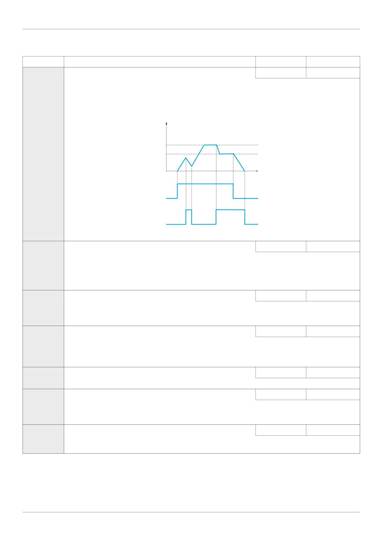
F390
[LL for ov.cur. prev.] Lower Limit function for Over Current Prevention
0.0 - UL
0.0
In the present software, motor speed is decreased to 0 Hz in case the stall prevention state is continued.
When motor speed is lower than F390 during stall prevention, motor speed is kept to F390 to increase motor current.
In this situation, motor current is beyond stall prevention level (F601 or F185), therefore over current or over load
detected fault may occur in some case.
Output Frequency (Hz)
Frequency command
F390
0
Time
ON
RUN command (F or R)
OFF
ON
Over current alarm status
OFF
F480
[No load cur. coef]
Magnetizing current coefficient
100 to 130%
100%
Use parameter F480 to fine-tune motor torque during low-speed operation. To increase motor torque in the low-speed
operating range, increase the setting of parameter F480. However, only adjust parameter F480 if an auto tune does
not yield sufficient low-speed torque. Increasing the setting of parameter F480 may increase the motor’s no-load current
during low-speed operation. Do not set this parameter so that the motor’s no-load current exceeds its rated operating
current.
F485
[Stall control coef. 1] Stall prevention control coefficient 1
10 to 250
100
Use parameter F485 to adjust the drive’s response to large, sudden changes in load when the motor is operated above
its rated frequency. If a sudden change in load causes the motor to stall before the drive goes into current limit, gradually
reduce the setting of F485.
F492
[Stall control coef. 2] Stall prevention control coefficient 2
50 to 150
100
Use parameter F492 to adjust the drive’s response to a drop in the line supply voltage when the motor is operated above its
rated frequency. Such a drop in voltage often causes fluctuations in motor current or vibration in the motor. To reduce these dis-
turbances, set parameter F492 to a value from 80 to 90.
Note: Reducing the F492 setting increases the motor running current level.
F494
[Mot. adj coefficient] Motor adjustment coefficient
-
-
DO NOT ADJUST.
F495
[Motor voltage coef.] Maximum voltage adjustment coefficient
90 to 120%
104%
Use parameter F495 to limit the drive’s maximum output voltage. Increasing this setting increases torque when the
motor is operated above its rated frequency, but may also cause motor vibration. Do not increase the value of F495 if
motor vibrations occur.
F496
[PWM adj. coef.]
Waveform switching adjustment coefficient
0.1 to 14.0 kHz
14.0 kHz
Adjusting the value of parameter F496 may reduce motor noise and vibration during PWM waveform frequency shifts
in the mid-speed operating range.
77
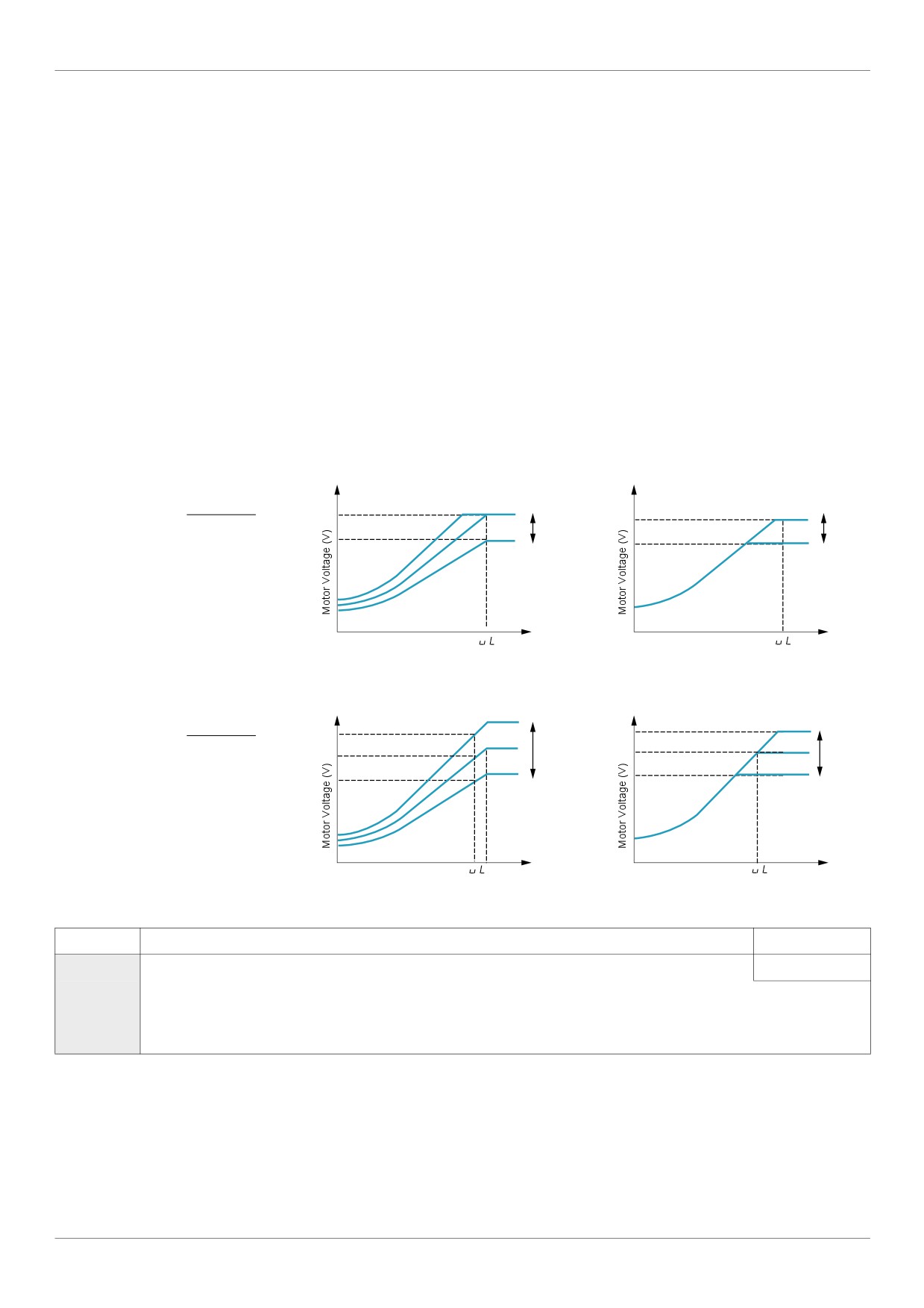
Motor Control Parameters
Supply Voltage Correction and Motor Voltage Limitation
The setting of parameter F307 determines:
If the drive’s voltage output will be corrected for fluctuations in the line supply voltage, or
If the drive’s voltage output will be limited, despite increases in the line supply voltage.
The drive’s output voltage will not exceed the input supply voltage.
If parameter F307 is set to 0 or 2, no corrections are made in the motor voltage gating process in response
to fluctuations in supply voltage. As a result, the V/Hz value of the output waveform to the motor will change in
proportion to the input voltage. Conversely, if F307 is set to 1 or 3, the V/Hz value of the output waveform will
be held constant, despite changes in the supply voltage level.
If parameter F307 is set to 0 or 1, output motor voltage will be limited to the value set by parameter
[Motor rated voltage] (uLu) (see page 74), even if the input supply voltage rises. If F307 is set to 2 or 3,
output motor voltage can rise above the level set by uLu if the input supply voltage rises above the motor rated
voltage.
If parameter [Mot cont. mode sel.] (Pt) is set to a value of 2, 3, 4, 5, or 6, the supply voltage is corrected,
regardless of the setting of parameter F307.
The diagrams below illustrate the impact of each setting of parameter F307.
F307 = 0
F307 = 1
Supply Voltage uncorrected, Motor Voltage Limited
Supply Voltage corrected,
Motor Voltage Limited
uLu
Input Voltage High
Input Voltage High
x Input Voltage
Rated Voltage
Low
Low
0
0
Output
Output
Frequency
Frequency
F307 = 2
F307 = 3
Supply Voltage uncorrected, Motor Voltage Unlimited
Supply Voltage corrected,
Motor Voltage Unlimited
Input Voltage High
Input Voltage High
uLu
x Input Voltage
Rated Voltage
Low
Low
0
0
Output
Output
Frequency
Frequency
Code
Name / Description
Factory setting
F307
[Mot volt limitation] Supply Voltage Correction and Motor Voltage Limitation
3
0
[Motor volt limit]: Supply voltage uncorrected - motor voltage limited
1
[Line&mot correct.]: Supply voltage corrected - motor voltage limited
2
[No action]: Supply voltage uncorrected - motor voltage unlimited
3
[U Line correction]: Supply voltage corrected - motor voltage unlimited
78
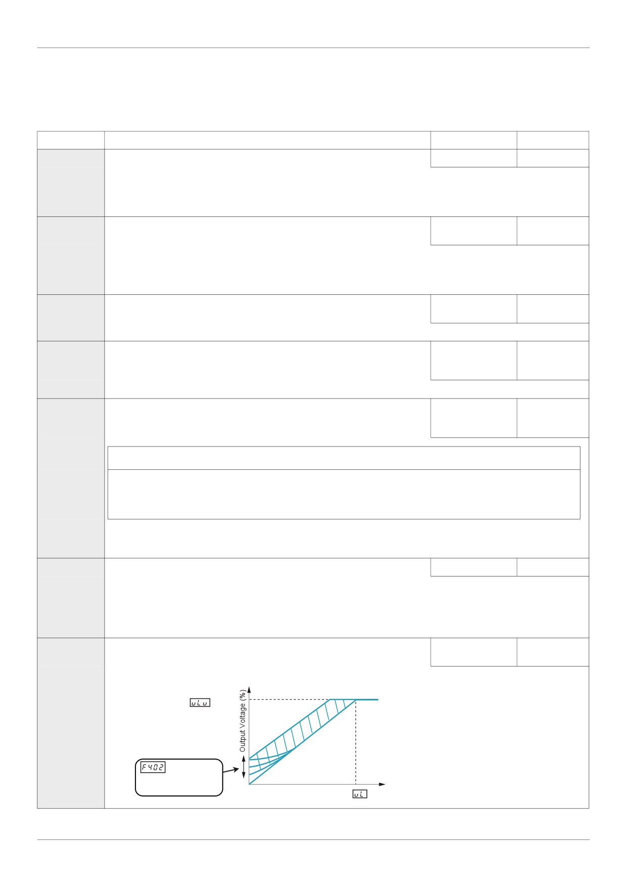
Motor Control Parameters
Motor 2 Control Parameters
When logic inputs assigned to functions 39 or 40 are active, parameters F170 to F173 and F185 are the
active set of motor control parameters.
When motor 2 control parameters are active, only constant V/Hz Motor Control Mode ([Mot cont. mode sel.]
(Pt) = 0) is available (see page 71).
Code
Name / Description
Adjustment range
Factory setting
F170
[Mot 2 rated Freq.]
Motor 2 rated frequency
25.0 to 400.0 Hz
50.0 Hz
Set parameter F170 to the motor’s rated frequency as indicated on the motor nameplate.
Note: It is possible to set the drive’s various motor control frequencies to 50 Hz by setting [Parameter reset] (tYP) to 1, the 50
Hz reset. For more information, see page 66.
F171
[Motor 2 rated Volt]
Motor 2 rated voltage
According to drive
According to
rating (1)
drive rating (1)
Set parameter F171 to the motor’s rated voltage as indicated on the motor nameplate.
ATV212pppM3X: 50...330 V.
ATV212pppN4: 50...660 V
Note: Drive output voltage cannot be set to exceed the input line voltage.
F172
[Motor 2 Volt Boost] Motor 2 voltage boost
0 to 30%
According to
drive rating (1)
F173
[Motor 2 Overload]
Motor 2 rated current overload setting
10 to 100% of the
100%
drive’s output cur-
rent rating
Set parameter F173 to the motor’s rated current as listed on the motor nameplate for the selected operating voltage.
F185
[Mot. 2 current limit] Motor 2 current limit
10 to 100% of the
110%
drive’s output cur-
rent rating
NOTICE
RISK OF DAMAGE TO THE MOTOR AND THE DRIVE
Check that the motor will withstand this current.
Check that the profile mission complies with the derating curve given in the installation manual.
Failure to follow this instruction can result in equipment damage.
Adjust parameter F185 to limit current during motoring or braking.
Do not set parameter F185 below the no-load current rating of the motor; otherwise, the drive will determine that motor braking
is taking place and will increase the frequency applied to the motor.
F401
[Slip Compensation]
0 to 150%
50%
If [Driving Scroll] (F324) page 160 is set to [yes] (1) the setting is replaced by 0%.
Before adjusting parameter F401, verify that parameter [Motor rated speed] (F417) (see page 74) is set to the rated
speed of the motor in rpm. Parameter F401 can be used to fine tune the drive’s slip compensation feature. Increasing
the value of parameter F401 increases the drive’s compensation of motor slip.
F402
[Auto Torque Boost]
0.0 to 30.0%
According to
drive rating (1)
Use parameter F402 to adjust the amount of automatic torque boost that is applied.
Motor rated voltage
: Automatically
adjusts the
amount of
0
torque boost.
Motor Rated Frequency
Output Frequency (Hz)
(1) See table page 199.
79