DYNAPAC Vibratory roller CC424/524/624HF, CC4200/5200/6200. Instruction manual (2018) - page 3
Operation
If the forward/reverse lever is moved quickly (forwards
or backwards) toward/past neutral, the system
switches to a rapid braking Mode and the machine
stops.
Activate normal driving Mode again by moving the
forward/reverse lever back to neutral.
Emergency braking
Braking is normally activated using the
forward/reverse lever. The hydrostatic transmission
1
retards and slows the roller when the lever is moved
towards the neutral position.
2
A disc brake in each drum motor/drum gear and the
rear axle also acts a secondary brake when in motion,
and as a parking brake when stationary. Activated with
the parking brake (2).
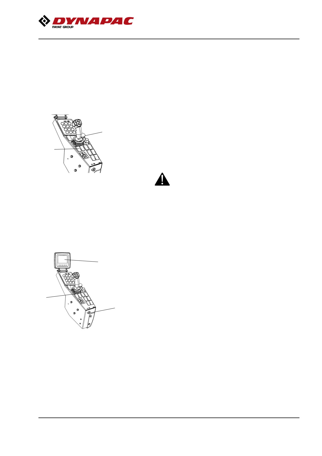
For emergency braking, press the emergency stop
Fig. Control panel
(1), hold the steering wheel firmly and be prepared
1. Emergency stop
for a sudden stop. The engine stops.
2. Parking brake
The Diesel engine will stop and must be restarted.
After emergency braking, return the forward/reverse
lever to neutral and deactivate the emergency stop.
Switching off
Set the speed control in idling position and allow the
1
engine to idle for a few minutes to cool down.
Check the display to see if any faults are indicated.
Switch off all lights and other electrical functions.
Activate the parking brake (3) and then turn the
3
ignition lock (2) to the left to the off position.
2
Fit the instrument cover on the display and top of the
control box (on rollers without cab), and lock it.
Fig. Control panel
1. Display
2. Ignition lock
3. Parking brake
69
Operation
Parking
Chocking the drums
Never disembark from the machine when the
diesel engine is running, unless the parking brake
is activated.
Make sure that the roller is parked in a safe place
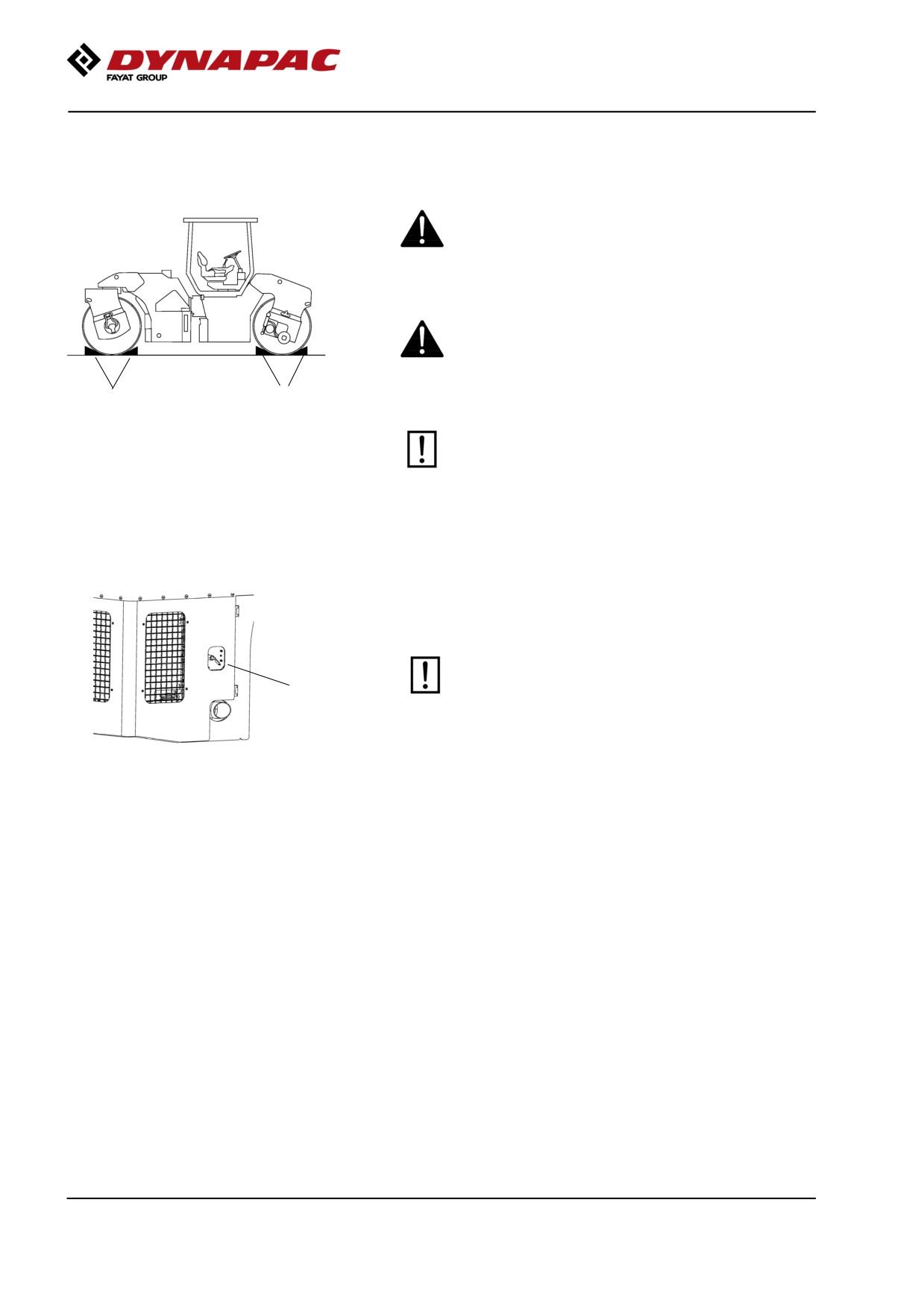
with respect to other road users. Chock the drums
if the roller is parked on sloping ground.
1
1
Fig. Positioning
Keep in mind that there is a risk of freezing during
1. Chocks
the winter. Drain the water tanks, pumps and
water lines.
Fill antifreeze in the engine cooling system and
the washer fluid reservoir in the cab. Also see
maintenance instructions.
Master switch
Before leaving the roller for the day, switch the master
switch (1) to the disconnected position and remove the
handle.
Before switching off the master switch, wait for at
least 30 seconds after the ignition lock has been
1
switched off, in order to avoid the engine's
electronic control unit (ECU) sustaining damage.
Figure. Engine door, left
1. Master switch
This will prevent battery discharging and will also
make it difficult for unauthorized persons to start and
operate the machine. Lock the service doors/covers.
70
Long-term parking
Long-term parking
The following instructions should be followed
when long term parking (more than one month).
These measures apply when parking for a period of up
to 6 months.
Before re-commissioning the roller, the points marked
with an asterisk * must be returned to the pre-storage
state.
Wash the machine and touch up the paint finish to
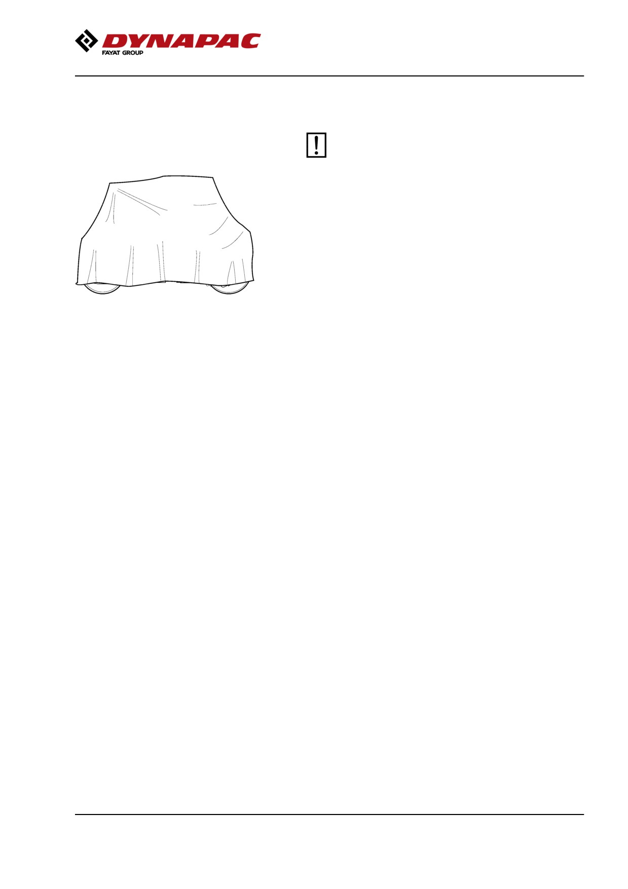
Fig. Roller weather protection
avoid rusting.
Treat exposed parts with anti-rust agent, lubricate the
machine thoroughly and apply grease to unpainted
surfaces.
Engine
* Refer to the manufacturer’s instructions in the engine
manual that is supplied with the roller.
Battery
* Dismantle the battery/batteries from the machine,
clean the outside and maintenance charge.
Air cleaner, exhaust pipe
* Cover the air cleaner (see under the heading 'Every
50 hours of operation' or 'Every 1000 hours of
operation') or its opening with plastic or tape. Also
cover the exhaust pipe opening. This is to avoid
moisture entering the engine.
Watering system
* Empty the water tank and all hoses of water. Empty
the filter housing and the water pump. Undo all
sprinkler nozzles.
Fuel tank
Fill the fuel tank completely full to prevent
condensation.
Hydraulic reservoir
Fill the hydraulic reservoir to the uppermost level mark
(see under the heading ‘Every 10 hours of operation.’)
71
Long-term parking
Hoods, tarpaulin
* Lower the instrument cover over the instrument
panel.
* Cover the entire roller with a tarpaulin. A gap must
be left between the tarpaulin and the ground.
* If possible, store the roller indoors and ideally in a
building where the temperature is constant.
Steering cylinder, hinges, etc.
Grease the steering cylinder piston with conservation
grease.
Grease the hinges on the doors to the engine
compartment and the cab.
72
Miscellaneous
Miscellaneous
Lifting
Locking the articulation
Articulation must be locked to prevent inadvertent
turning before lifting the roller.
Turn the steering wheel so the roller is straight forward.
Activate the parking brake and switch off the machine.
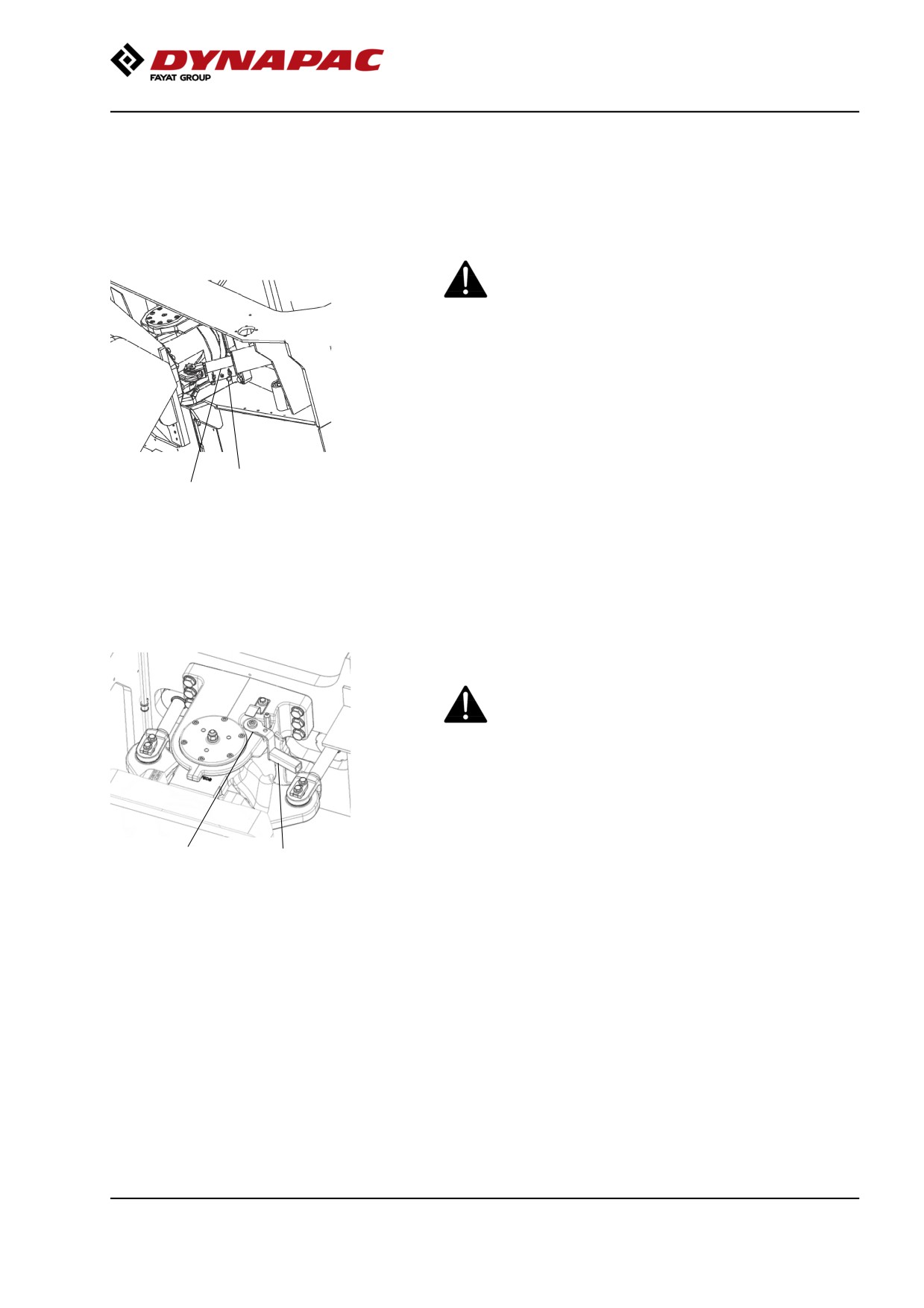
Put the locks on the guide cylinder piston rods and
lock them.
1
2
Figure. Articulation in locked position
1. Cotter pin
2. Lock
Locking the articulation
Articulation must be locked to prevent inadvertent
turning before lifting the roller.
Turn the steering wheel to the straight ahead position.
Activate the parking brake.
Front frame shall be in line with the rear frame.
2
1
Fig. Steering joint lock, locked
Lift lock in the handle (1) while it is turned clockwise.
1. Lock handle
2. Locking dowel
Make sure dowel (2) gets in position as illustrated.
Arm must be in contact with the surface of the molded
holder.
If this is not done, it's likely that the machine halves
are out of line, steer then the machine so this is
happening.
73
Miscellaneous
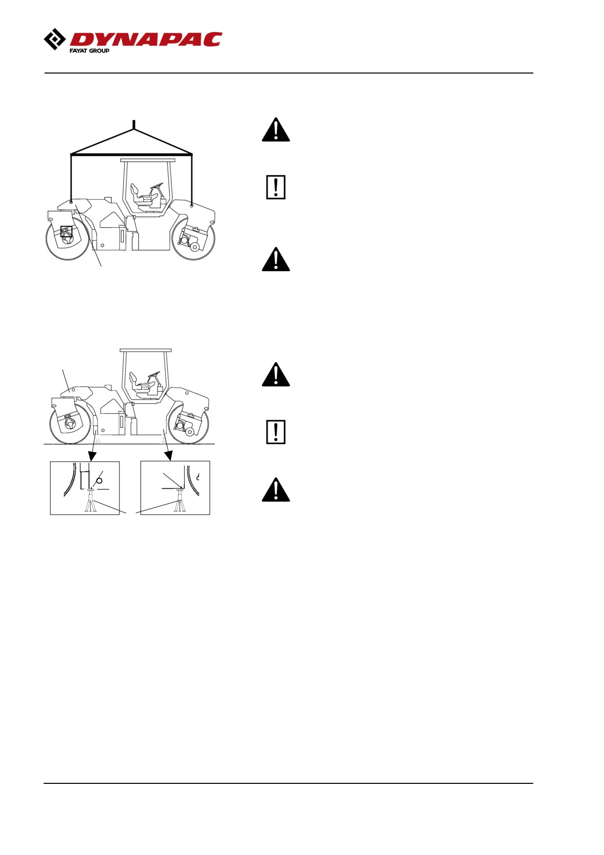
Weight: refer to the
hoisting plate on the
Lifting the roller
roller
The machine’s gross weight is specified on the
hoisting plate (1). Refer also to the Technical
specifications.
Lifting equipment such as chains, steel wires,
straps and lifting hooks must be dimensioned in
accordance with the relevant safety regulations
for the lifting equipment.
Stand well clear of the hoisted machine! Make sure
that the lifting hooks are properly secured.
1
Fig. Roller prepared for lifting
1. Hoisting plate
Weight: refer to the hoisting plate on the
roller
Lifting the roller with jack:
1
The machine’s gross weight is specified on the
hoisting plate (1). Refer also to the Technical
specifications.
The lifting device such as a jack (2), or
equivalent, must be dimensioned according to the
safety regulations for lifting devices.
3
3
Do not go under a lifted load! Make sure that the
lifting device is secure in its position, and on a
level and stable suface.
2
Figure. Roller lifted with jack
1. Lifting plate
2. Jack
The machine must only be lifted with a jack, or the
3. Marking
like, positioned as per the markings (3). The frame is
reinforced at these points to withstand the tension.
Lifting at any other place can result in damage to the
machine or personal injury.
74
Miscellaneous
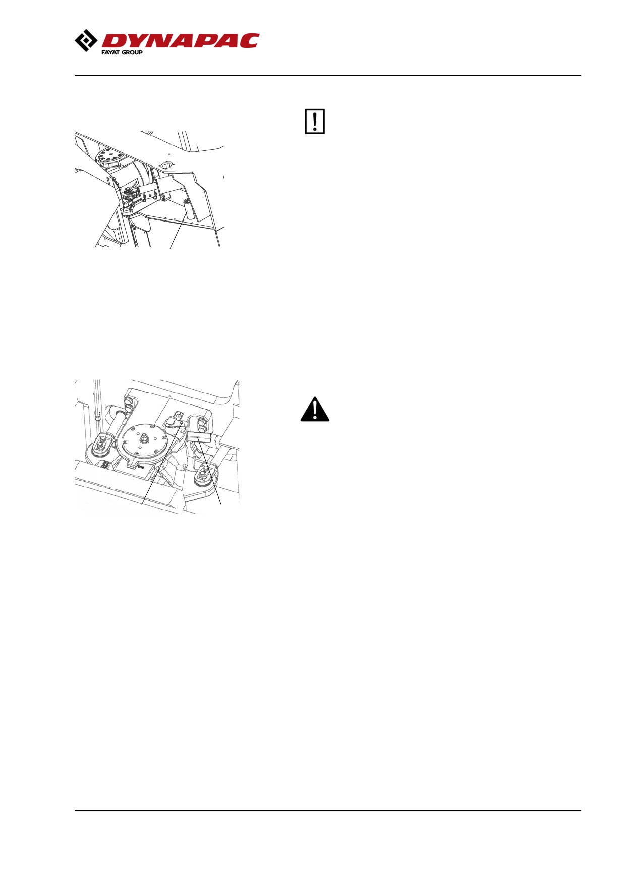
Unlocking the articulation
Remember to unlock the articulation before
operating.
Insecure and remove the locking devices and put them
in the storing place.
2
Figure. Articulation in open position
2. Lock
Unlocking the articulation
Remember to restore the steering joint lock on the
steering joint to open before operating.
Lift lock in the handle while turning it counterclockwise.
Make sure lock gets in position on the dowel by trying
2
1
to turn the handle clockwise or counterclockwise
Fig. Steering joint lock, open
without lifting the lock.
1. Lock handle
2. Locking dowel
Towing/Recovering
The roller can be moved up to 300 meters (330 yards)
using the instructions below.
75
Miscellaneous
Short distance towing with the engine running
Activate the parking brake, and temporarily stop
the diesel engine. Chock the drums to prevent the
roller from moving
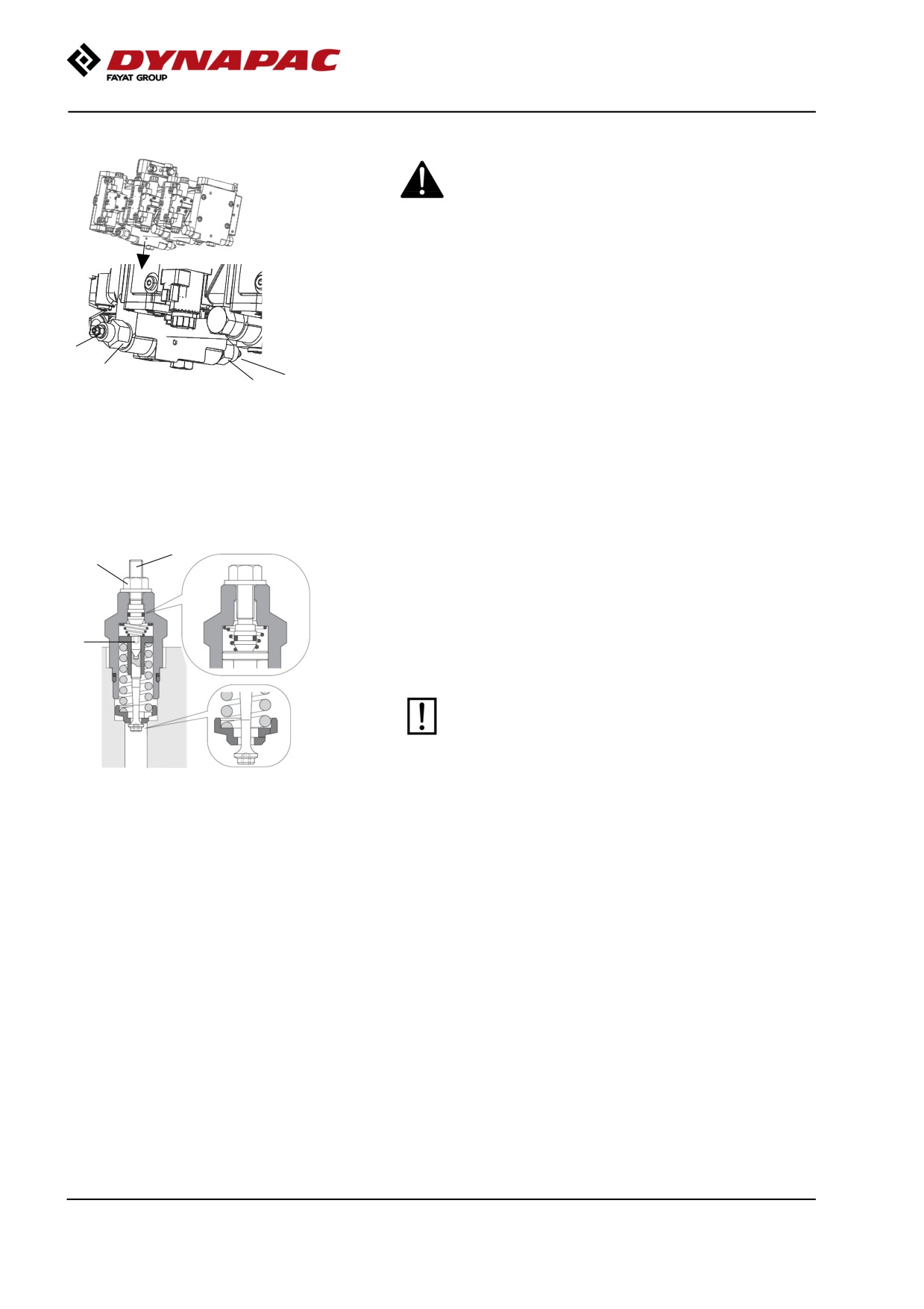
Open the left door to the engine compartment to
access the propulsion pump.
At the bottom on the forward drive pump are two
towing valves (1) which need to be set in bypass mode.
1
Loosen the towing valve (1) with the hexagonal nut (A)
2
1
2
by turning it a number of turns to the left, counter-hold
Fig. Propulsion pump
on the overflow valve (2).
1. Towing valve
2. Bypass valve
After releasing the hexagonal nut (A), screw in the
adjusting screw (B) with a hex key until it touches the
pin (C) and then turn an additional ½ turn. The valve is
now open.
B
Start the engine and allow it to idle.
A
Deactivate the parking brake and place the
forward/reverse lever in the forward or reverse
position. If the lever is in neutral, the brakes in the
hydraulic motors are activated.
C
The roller can now be towed and can also be steered
if the steering system is otherwise functioning.
Do not forget to reset the towing valves after
performing towing.
Figure. Towing valve
To leave the by-pass position, unscrew the adjusting
screw (B) until it stops and then lock the valve again
with the hex nut (A).
76
Miscellaneous
Short distance towing when the engine is
inoperative.
Chock the drums to prevent the roller from moving
when the brakes are hydraulically disengaged.
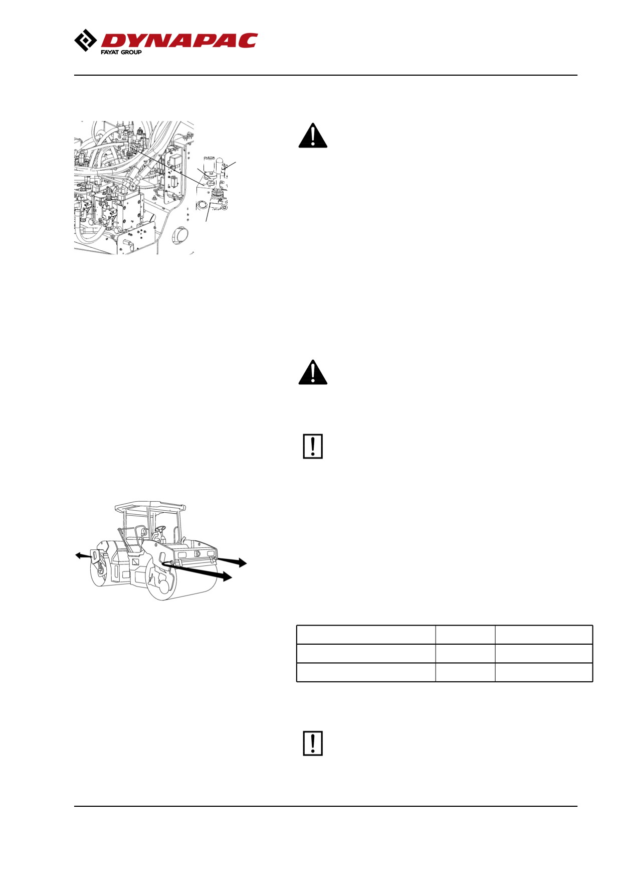
2
3
Open both towing valves as described earlier.
The brake disengagement pump is located behind the
1
left door of the engine compartment.
Make sure that the valve (1) is closed, this is done by
Fig. Brake disengagement valve
tightening clockwise with the knob (3). Pump with the
1. Valve
pump arm (2) until the brakes are disengaged.
2. Pump arm
3. Knob
Ensure that the valve is reset into open position after
finished towing. This is done by turning the knob
counter clockwise to full extracted position.
Towing the roller
When towing/recovering, the roller must be braked
by the towing vehicle. A towing bar must be used
as the roller has no brakes.
The roller must be towed slowly, max. 3 km/h (2
mph) and only towed short distances, max. 300 m
(330 yards).
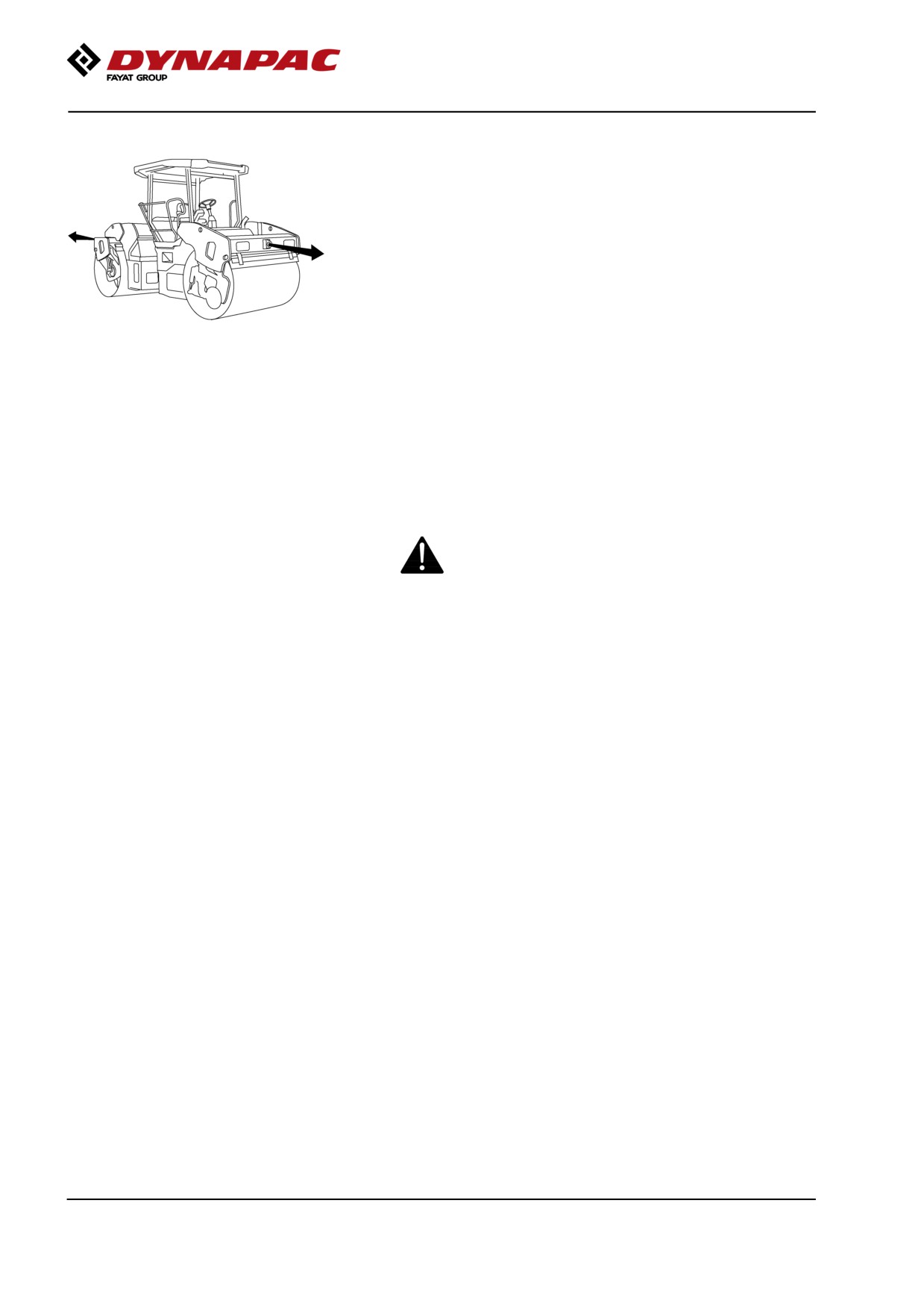
When towing/retrieving a machine, the towing device
must be connected to both lifting holes in the diagram.
The load is uniformly divided between the two lugs.
The pulling forces should act parallel to the machine's
longitudinal axis, as shown in the figure. See table
below for maximum permitted pulling force.
Fig. Towing
Model
kN
lbf
CC224-384, CC2200-3800
140
31 500
CC424-624, CC4200-6200
190
42 750
Reverse the towing preparations made to the
hydraulic pump and/or the motor.
77
Miscellaneous
Trailer eye
The roller can be fitted with a trailer eye.
The trailer eye is not designed to be used for
towing/recovering. It is designed for trailers and other
towed objects weighing no more than 2 600 kg (5 750
lbs).
Fig. Trailer eye
Transport
Tie-down and secure the machine according to the
Cargo Securing Certificate for the specific machine if
this is avaliable and applicable.
If not, tie down and secure the machine according to
the cargo securing rules that are valid for the country
where the transport takes place.
Never lash over the machine’s articulated joint, nor
over the machine’s operator platform.
Before securing the machine ensure that :
• the parking brake is applied and in good working condition
• the articulated joint is in closed position
• the machine is centered laterally on the platform
• the lashings are in good condition and fulfills the
corresponding rules for transport securing.
78
Miscellaneous
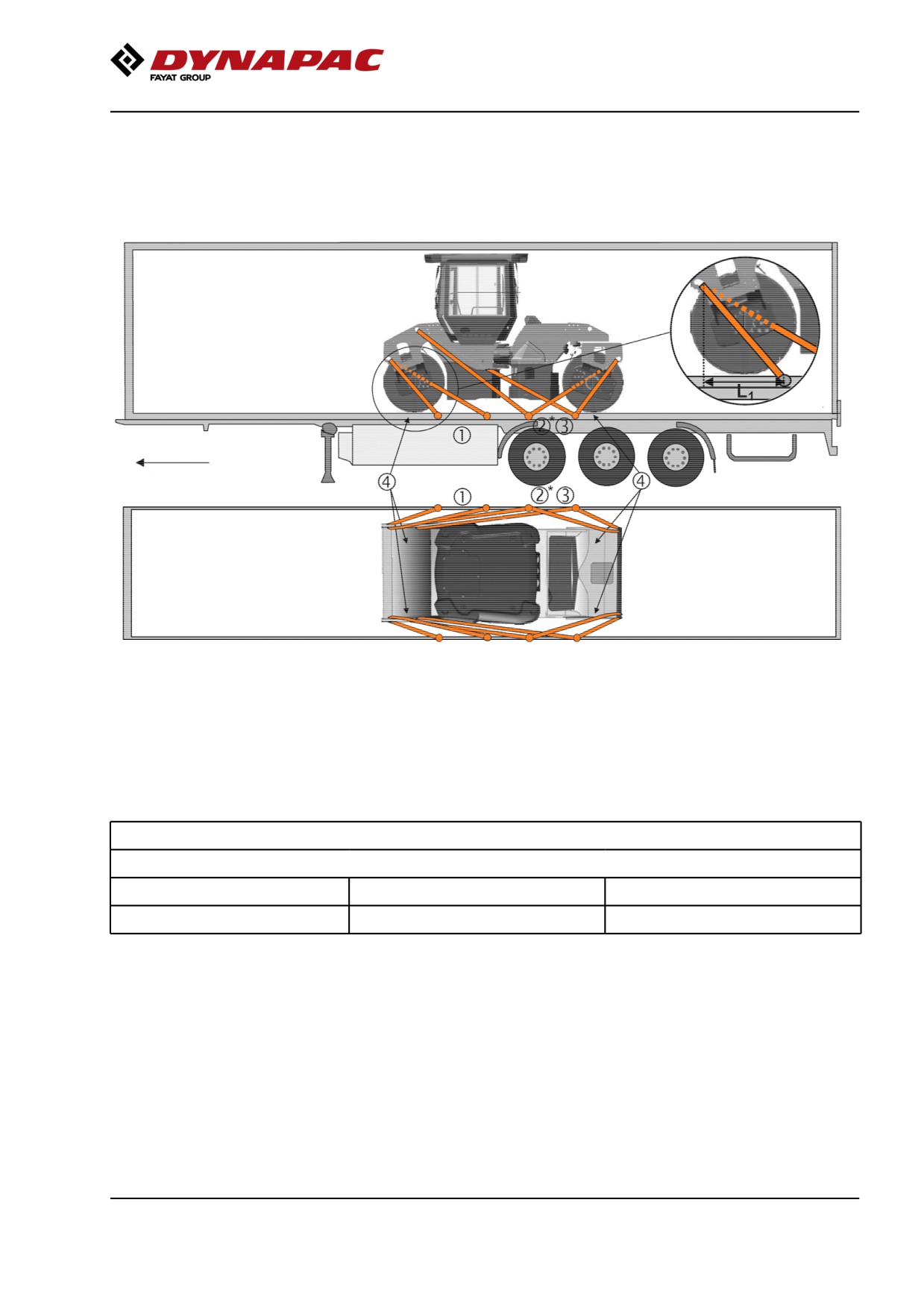
Loading CC224-624, CC2200-6200
Securing vibratory roller CC224-624, CC2200-6200
from Dynapac for transport.
(The instructions also apply to Combi machines)
Roller loaded in
forward
direction
Direct of travel
*)
Lashing 2 to be moved to a rear lashing point if side beam on the trailer is missing.
1 - 3
= double lashings, i.e. one lashing with two parts secured to two different lashing mounts,
symmetrically located on the right and left sides.
4
= rubber
The lashings' permitted distance interval in meters
(1 - 3: Double lashings, LC at least 1.7 tonnes (1700 daN), STF 300 kg (300daN))
Double L1
Double L2
Double L3
0,9 - 2,5
0,8 - 2,5
0,1 - 2,5
For lashing 1 is L1 the distance between the lashing point on the edge of the platform and the point directly sideways
from the lashing point on the roller perpendicular to the platform edge. The relationship for lashings L2 and L3 is the
same.
79
Operating instructions - Summary
Load carrier
-
When loaded, the vibratory roller is centered laterally on the platform (± 5 cm).
-
The parking brake is applied and in good working condition, and the articulated joint lock is
closed.
-
The drums are placed on rubber liners, so that the static friction between the surfaces is at
least 0.6.
-
The contact surfaces must be clean, wet or dry, and free from frost, ice and snow.
-
The lashing mounts on the load carrier have LC/MSL at least 2 tonnes.
Lashings
-
The lashings comprise a lashing strap or chain with a permitted load (LC/MSL) of at least 1.7
tonnes (1,700 daN) and a pre-tension STF of at least 300 kg (300 daN). The lashings are
re-tightened as required.
-
Each of lashings 1-3 is either a double or two single lashings. A double lashing runs in a sling
through a lashing point or around a machine part and down into two different fasteners on the
platform. Note that lashing 2 may be moved to a rear lashing point if side beam on the trailer is
missing.
-
Lashings in the same direction are placed in different lashing mounts on the trailer. Lashings
that are pulled in opposite directions may be placed in the same lashing mount, however.
-
The lashings are as short as possible.
-
The lashing hooks must not lose grip if the lashings become slack.
-
The lashings are protected against sharp edges and corners.
-
The lashings are located symmetrically in pairs on the right and left sides.
80
Operating instructions - Summary
Operating instructions - Summary
1.
Follow the SAFETY INSTRUCTIONS specified in the Safety Manual.
2.
Make sure that all instructions in the MAINTENANCE section are followed and the
steering hitch lock is unlocked.
3.
Turn the master switch to the ON position.
4.
Move the forward/reverse lever to the NEUTRAL position. Sit down in the seat.
5.
Engage the parking brake.
6.
Disengage the emergency stop. The roller is always starting in transportation
mode.
7.
Set the rpm switch in position idle (LO).
8.
Start the engine and allow it to warm up.
9.
Set the rpm switch in position working speed (HI) or (ECO).
10. Disengage the parking brake.
11. Drive the roller. Operate the F/R lever with care.
12. Test the brakes. Remember that the braking distance will be longer if the
hydraulic fluid is cold.
13. Set the transportation/working mode button in position working mode.
14. Use vibration only when the roller is in motion.
15. Check that the drums are thoroughly watered when watering is required.
16. IN AN EMERGENCY:
- Press the EMERGENCY STOP.
- Hold the steering wheel firmly.
- Brace yourself for a sudden stop.
17. When parking:
- Activate the parking brake.
- Switch off the engine and block the drums if the roller is on an inclined surface.
18. When lifting: - Refer to the relevant section in the Instruction Manual.
19. When towing: - Refer to the relevant section in the Instruction Manual.
20. When transporting: - Refer to the relevant section in the Instruction Manual.
81
Operating instructions - Summary
21. When recovering - Refer to the relevant section in the Instruction Manual.
82
Preventive maintenance
Preventive maintenance
Complete maintenance is necessary for the machine
to function satisfactorily and at the lowest possible
cost.
The Maintenance section includes the periodic
maintenance that must be carried out on the machine.
The recommended maintenance intervals assume that
the machine is used in a normal environment and
working conditions.
Acceptance and delivery inspection
The machine is tested and adjusted before it leaves
the factory.
On arrival, before delivery to the customer, delivery
inspection must be conducted as per the check list in
the warranty document.
Any transport damage must be reported immediately
to the transport company, as this is not covered by the
product warranty.
Warranty
The warranty is only valid if the stiplulated delivery
inspection and the separate service inspection have
been completed as per the warranty document, and
when the machine has been registered for starting
under the warranty.
The warranty is not valid if damage has been caused
by inadequate service, incorrect use of the machine,
the use of lubricants and hydraulic fluids other than
those specified in the manual, or if any other
adjustments have been made without the requisite
authorisation.
83
Preventive maintenance
84
Maintenance - Lubricants and symbols
Maintenance - Lubricants and symbols
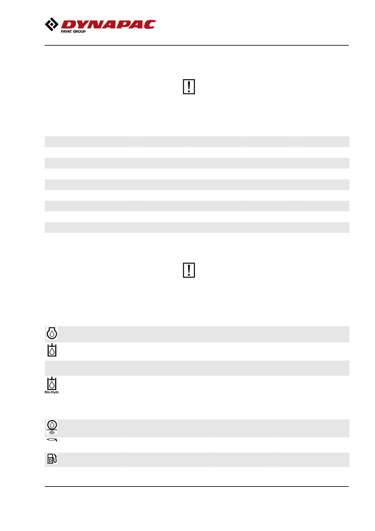
Always use high-quality lubricants and the
amounts recommended. Too much grease or
oil can cause overheating, resulting in rapid
wear.
Fluid volumes
Drum
- Drum CC424, CC4200
14 liters
15 qts
- Drum CC524, CC5200
15 liters
16 qts
- Drum CC624, CC6200
17 liters
18 qts
- Drum gear
1,5 liters
1.6 qts
Hydraulic reservoir
40 liters
42 qts
Diesel engine
- oil
11 liters
11.6 qts
- coolant, no cab
21,4 liters
22.6 qts
- coolant, with cab
23,6 liters
25.0 qts
Other fuel and lubricants are required when
operating in areas with extremely high or
extremely low ambient temperatures. See the
‘Special instructions’ chapter, or consult
Dynapac.
ENGINE OIL
Air temperature -15°C - +50°C
Dynapac Engine oil
P/N 4812161855 (5 liters),
(5°F-122°F)
200
P/N 4812161856 (20 liters)
HYDRAULIC FLUID
Air temperature -15°C - +50°C
Dynapac Hydraulic
P/N 4812161868 (20 liters),
(5°F-122°F)
300
P/N 4812161869 (209 liters)
Air temperature over +40°C
Shell Tellus S2 V100
(104°F)
BIOLOGICAL
Air temperature -10°C - +35°C
PANOLIN HLP Synth
HYDRAULIC FLUID,
(14°F-95°F)
46
PANOLIN
When it leaves the factory, the
machine may be filled with
biologically degradable fluid. The
same type of fluid must be used
when changing or topping up.
DRUM OIL
Air temperature -15°C - +40°C
Dynapac Drum Oil
P/N 4812161887 (5 liters),
(5°F-104°F)
1000
P/N 4812161888 (20 liters)
GREASE
Dynapac Roller
P/N 4812030096
Grease (0.4kg)
FUEL
See engine manual.
-
-
85
Maintenance - Lubricants and symbols
TRANSMISSION OIL Air temperature -15°C (5°F) -
Dynapac Gear oil
P/N 4812161891 (5 liters),
above +40°C (104°F)
1000
P/N 4812161892 (20 liters)
COOLANT
Anti-freeze protection down to
Dynapac coolant
P/N 4812161854 (5 liters)
about -37°C (-34.6°F)
100 (mixed 50/50 with
water)
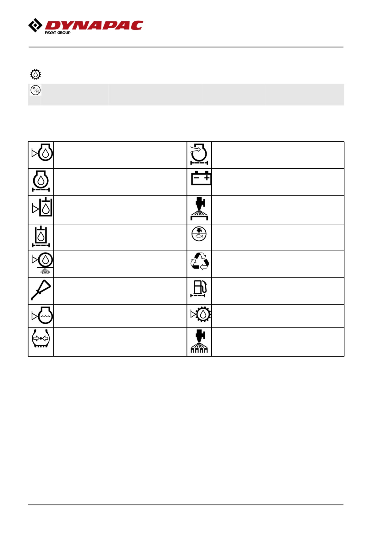
Maintenance symbols
Engine, oil level
Air filter
Engine, oil filter
Battery
Hydraulic reservoir, level
Sprinkler
Hydraulic fluid, filter
Sprinkler water
Drum, oil level
Recycling
Lubricating oil
Fuel filter
Coolant level
Pump gear, oil level
Air pressure
Sprinkler, tires
86
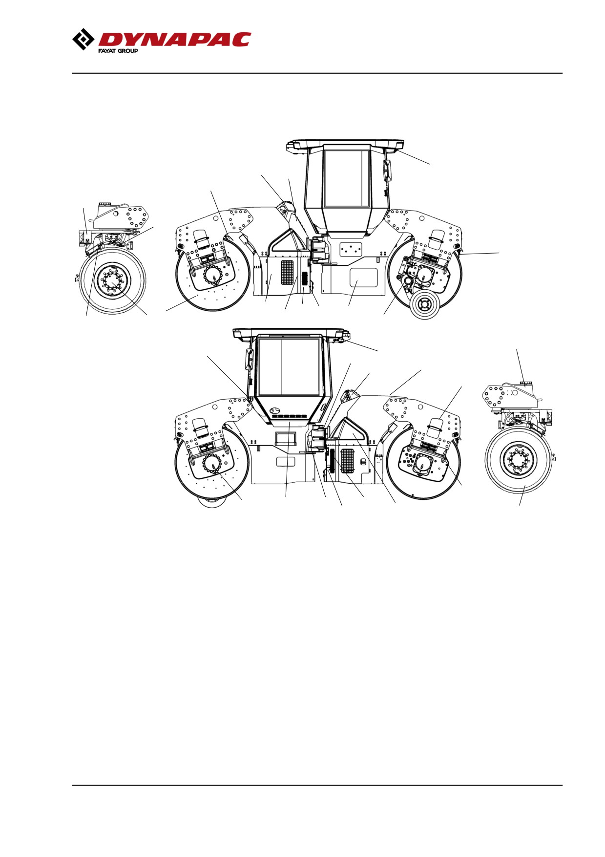
Maintenance - Maintenance schedule
Maintenance - Maintenance schedule
Service and maintenance points
9
5
22
14
14
14
12
1
2
20
14
15
3
12
24
13
11
23
17
8
6, 7
21
18
13
3
19
16
10
4
25
Fig. Service and maintenance points
1.
Engine oil
9.
Coolant
17. Steering joint
2.
Oil filter
10. Air cleaner
18. Seat bearing
3.
Fuel filter
11. Refueling point
19. Rubber element
4.
Hydraulic filter
12. Scrapers
20. Battery
5.
Hydraulic fluid level
13. Water tank(s), filling
21. Pivot bearing
6.
Hydraulic fluid, filling
14. Watering system
22. Cab, air filter
7.
Hydraulic tank cap
15. Drum gear/Wheel gear
23. Cab, AC
8.
Hydraulic fluid cooler
16. Drum oil
24. Edge cutter
25. Wheel
General
Periodic maintenance should be carried out after the
number of hours specified. Use the daily, weekly etc.
periods where number of hours cannot be used.
87
Maintenance - Maintenance schedule
Remove all dirt before filling, when checking
oils and fuel and when lubricating using oil or
grease.
The manufacturer’s instructions found in the
engine manual also apply.
Specific maintenance and checks on diesel
engines must be carried out by the engine
supplier’s certified personnel.
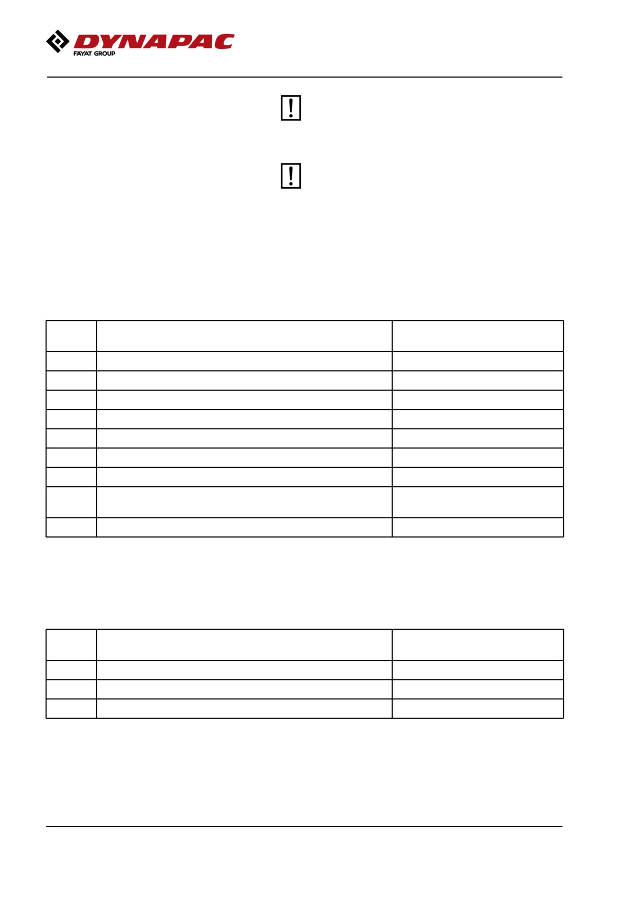
Every 10 hours of operation (Daily)
Refer to the contents to find the page number of the
sections referred to !
Pos.
Action
Comment
in fig
Before starting up for the first time on that day
1
Check the engine oil level
Refer to the engine manual
9
Check the engine coolant level
5
Check the hydraulic reservoir level
11
Refuel
13
Fill the water tanks
14
Check the sprinkler system
14
Check the Emergency watering (Extra pump in pump
system)
12
Check the scraper setting
After the FIRST 50 hours of operation
Refer to the contents to find the page number of the
sections referred to !
Pos.
Action
Comment
in fig
4
Change the hydraulic fluid filter
Refer to 1000h.
15
Change the oil in the drum gears
Refer to 1000h.
17
Steering hitch - Tightening
Refer to 1000h.
88
Maintenance - Maintenance schedule
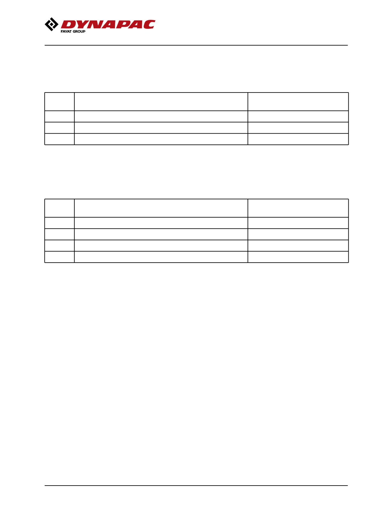
Every 50 hours of operation (Weekly)
Refer to the contents to find the page number of the
sections referred to !
Pos.
Action
Comment
in fig
15
Check the oil level in the drum gears
3
Draining the fuel prefilter
Check that hoses and connections are tight
Every 250/750/1250/1750
hours of operation
Refer to the contents to find the page number of the
sections referred to !
Pos.
Action
Comment
in fig
8
Clean the hydraulic fluid cooler/water cooler
Or when required
20
Check the batteries condition.
22,23
Check the AC
Optional
24
Check/lubricate the edge cutter
Optional
89
Maintenance - Maintenance schedule
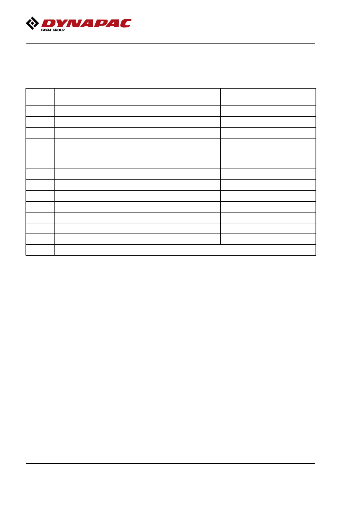
Every 500/1500 hours of operation
Refer to the contents to find the page number of the
sections referred to !
Pos.
Action
Comment
in fig
8
Clean the hydraulic fluid cooler/water cooler
Or when necessary
10
Check the filter element in the air cleaner
Replace when necessary
20
Check the condition of the batteries
1,2
Change the diesel engine oil and oil filter *, **
See the engine's instruction
manual
*) 500 h or once every 6
months
3
Replace fuel filter
Refer to the engine manual
3
Replace fuel prefilter
16
Check the oil level in the drums
19
Check rubber elements and bolted joints
18
Grease the chair bearing
22,23
Check the AC
Optional
21
Lubricate the pivot bearings
Optional
**) (IIIA/T3) Only applicable for correct fuel quality, otherwise change every 250 hours.
90
Maintenance - Maintenance schedule
Every 1000 hours of operation
Refer to the contents to find the page number of the
sections referred to !
Pos.Action
Comment
in
fig
10
Check the filter element in the air cleaner
Replace when necessary
20
Check the condition of the batteries
1,2
Change the diesel engine oil and oil filter *
See the engine's instruction manual
*) 500 h or once every 6 months
Check the engine belt drive system
Refer to the engine manual
3
Replace fuel filter
Refer to the engine manual
3
Replace fuel prefilter
Refer to the engine manual
16
Change the oil in the drums
15
Change the oil in the drum gears **
**)1000 h or every 12 months.
4
Change the hydraulic fluid filter
7
Check the hydraulic reservoir cover/breather
19
Check the rubber elements and bolted joints
18
Grease the chair bearing
22
Replace the air cleaner filter in the cab
Optional
21
Lubricate the pivot bearing
Optional
17
Steering hitch - Tightening
91
Maintenance - Maintenance schedule
Every 2000 hours of operation
Refer to the contents to find the page number of the
sections referred to !
Pos.
Action
Comment
in fig
10
Check the filter element in the air cleaner
Replace when necessary
1,2
Change the diesel engine oil and oil filter *
See the engine's instruction
manual
*) 500 h or once every 6
months
Check the engine belt drive system
Refer to the engine manual
Check the engine valve clearances
Refer to the engine manual
Replace the ventilation filter in the crankcase **
Refer to engine manual
**) only applies to IIIB/T4i
3
Replace fuel filter
Refer to the engine manual
3
Replace fuel prefilter
Refer to the engine manual
11
Drain and clean the fuel tank
16
Change the oil in the drums
15
Change the oil in the drum gears ***
***)1000 h or every 12 months
4
Change hydraulic fluid filter
6
Change the hydraulic fluid
13
Drain and clean the water tanks
17
Check the condition of the articulation
17
Steering hitch - Tightening
22
Replace the air cleaner filter in the cab
Optional
23
Overhaul the air conditioning
Optional
21
Lubricate the pivot bearing
Optional
92
Maintenance, 10h
Maintenance, 10h
Every 10 hours of operation (Daily)
Park the roller on a level surface.
The engine must be switched off and the
parking brake activated when checking or
adjusting the roller, unless otherwise specified.
Ensure that there is good ventilation (air
extraction) if the engine is run indoors. Risk of
carbon monoxide poisoning.
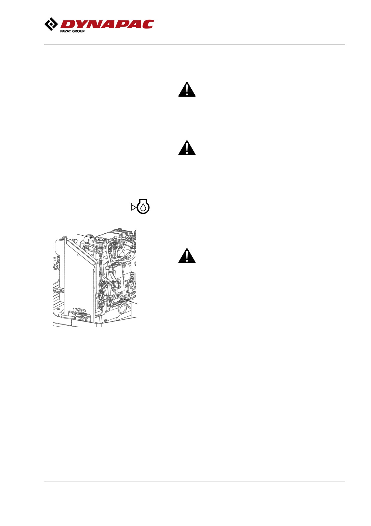
Diesel engine - Check oil level
2
The dipstick is accessed through the right door of the
engine compartment.
Take care not to touch any hot parts of the engine
or the radiator when removing the dipstick. Risk of
burns.
The dipstick is located down on the front of the engine.
1
Pull out the dipstick (1) and check that the oil level is
between the upper and lower marks.
For further details, refer to the engine's instruction
Fig. Engine compartment
manual.
1. Dipstick
2. Oil filler cap
93
Maintenance, 10h
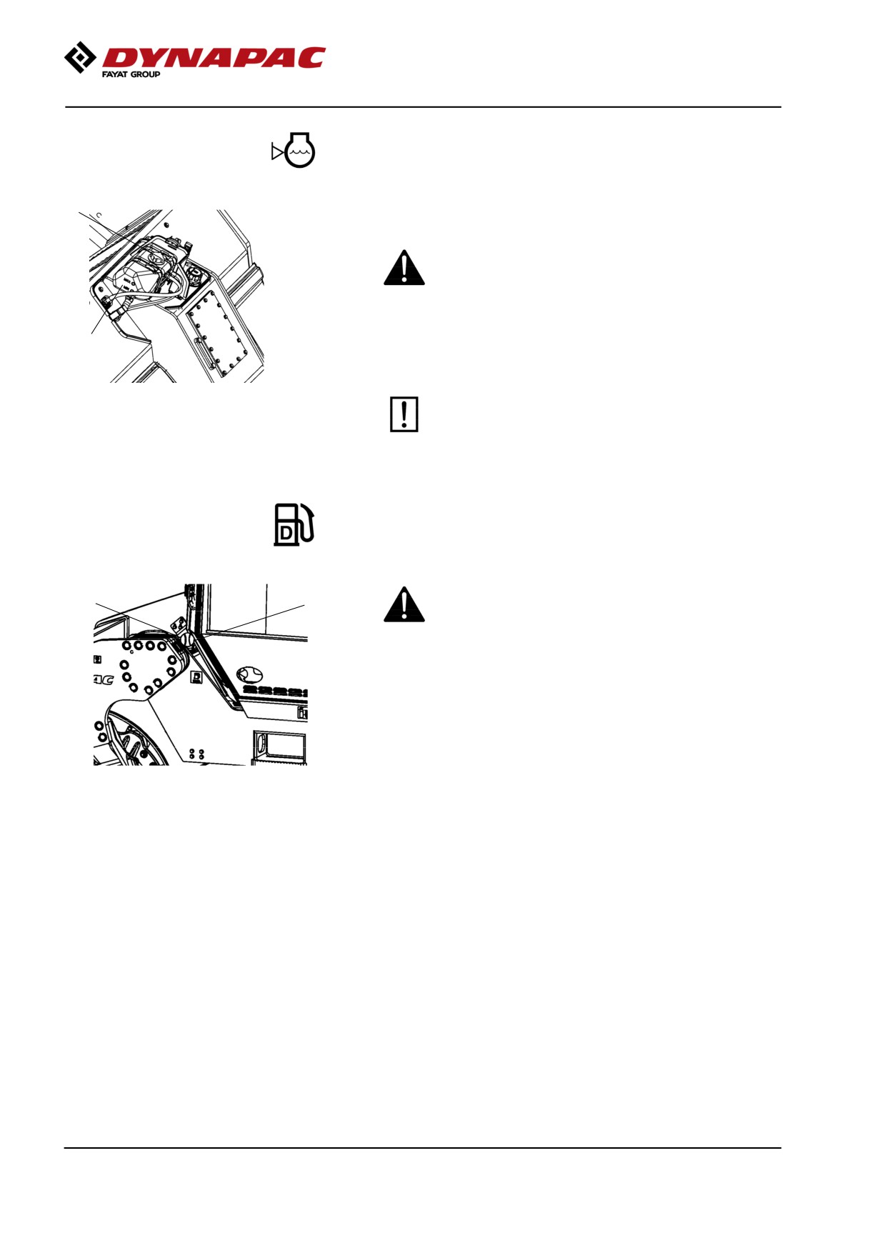
Coolant level - Check
1
Check that the coolant level is between the max. and
min. marks (2).
Observe great caution if the cap has to be opened
while the engine is hot. Wear protective gloves and
goggles.
2
Fill with a mixture of 50% water and 50% anti freeze.
See the lubrication specification in these instructions
and the engine manual.
Fig. Expansion tank
Flush the system every other year and change
1. Filler cap
the coolant. Also check that the air has
2. Level marks
unobstructed passage through the reservoir.
Fuel tank - Refueling
Never refuel while the engine is running. Do not
2
1
smoke and avoid spilling fuel.
The filler pipe and tank cap are on the left side of the
front frame.
Refuel the tank every day before starting work, or fill
Fig. Fuel tank
the tank at end of work. Unscrew the lockable tank cap
1. Tank cap
(1) and fill fuel up to the lower edge of the filler pipe.
2. Filler pipe
The tank holds 230 liters (60.7 gal) of fuel. Refer to the
engine manual for information on diesel grade.
94
Maintenance, 10h
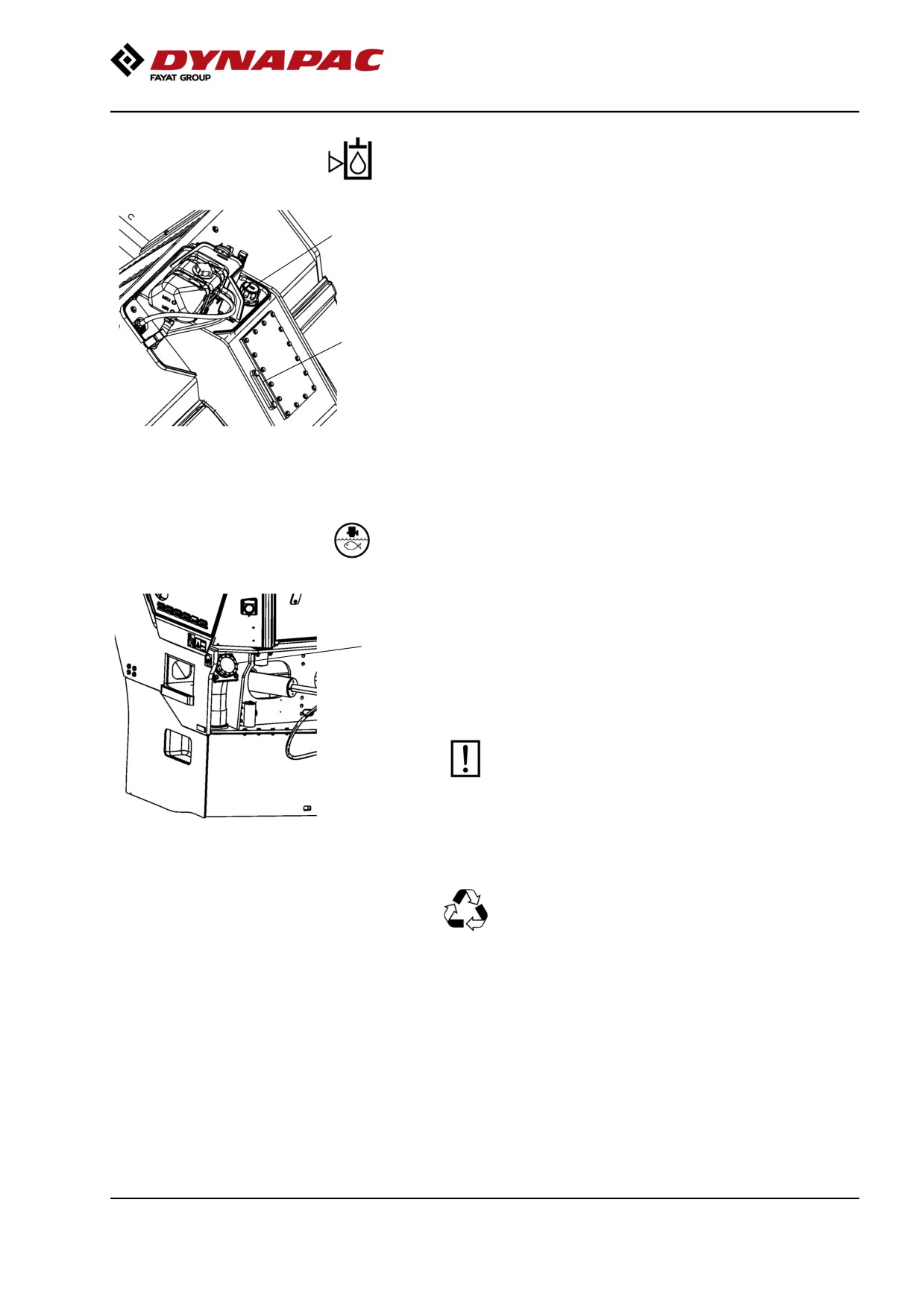
Hydraulic reservoir - Check fluid level
2
Place the roller on a level surface and check that the
oil level in the sight glass (1) is between the max and
min markings. Top up with the type of hydraulic fluid
specified in the lubricant specification, if the level is too
low.
1
Figure. Hydraulic reservoir
1. Oil sight glass
2. Filler cap
Water tank, Std - Filling
The filler cap is on the rear left side of the front frame.
1
The machine can also be fitted with refilling on both
sides.
When quick-filling on a machine with two filling pipes,
loosen the filler cap on the nonfilling side to ventilate
the water tank.
Unscrew the tank cap (1) and fill with clean
water. Do not remove the strainer (2).
Figure. Standard water tank
1. Tank cap
Fill the central (standard) tank, it holds 900 liters (238
gal).
Only additive: A small amount of
environment-friendly antifreeze.
95
Maintenance, 10h
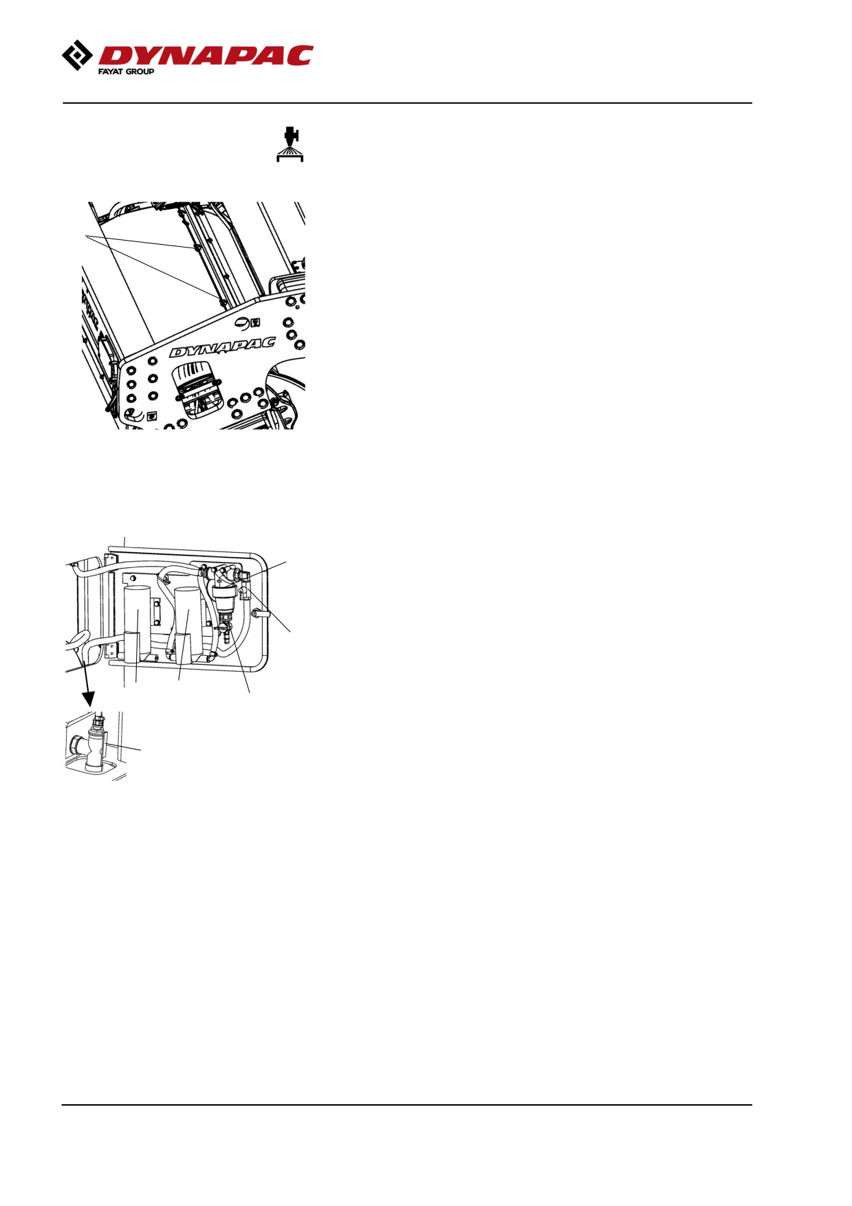
Sprinkler system/Drum
Check
Start the sprinkler system and make sure that none of
the nozzles (1) are clogged. If necessary, clean
1
blocked nozzles and the coarse filter placed by the
water pump (2). See next section.
Figure. Front drum
1. Nozzle
Cleaning the coarse filter
To clean the coarse filter (1) open the drain cock (3)
1
on the filter and allow any dirt to run out.
If necessary close the cock (2) and clean the filter and
filter housing. Check that the rubber gasket in the filter
housing is intact.
2
After inspecting and cleaning, reset and start the
system to check that it works.
6
4
3
There is a drain cock (5) in the space for the pump
system. This can be used to drain the tank and the
pump system.
5
An extra pump (6) can be installed in case the
standard water pump stops working. See section for
Figure. Pump system, front frame
emergency watering.
right side
1. Coarse filter
To drain the complete sprinkler system, see section for
2. Stop cock
Watering system - Draining, 2,000 h.
3. Drain cock kran, filter
4. Water pump
5. Drain cock
6. Extra pump (optional)
96
Maintenance, 10h
Sprinkler system/Drum
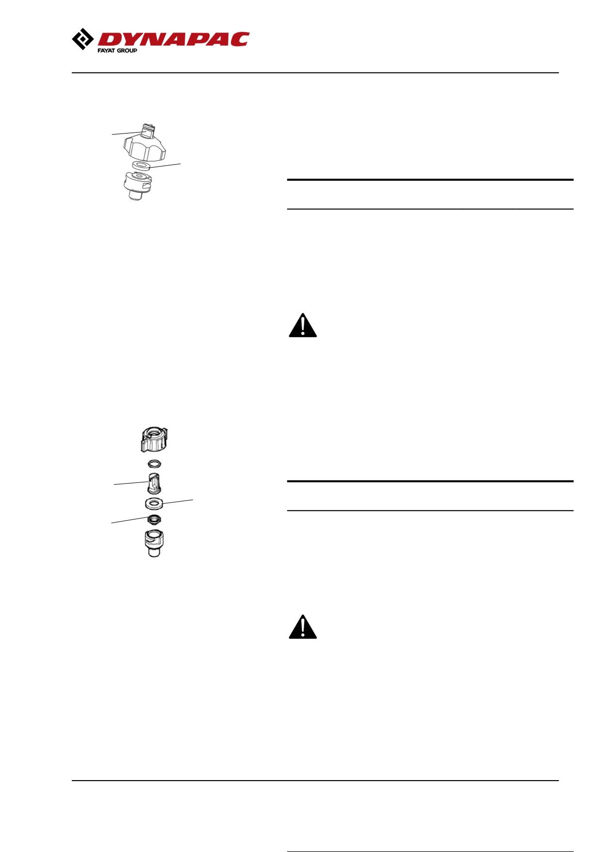
Cleaning of sprinkler nozzle
Dismantle the blocked nozzle by hand.
1
Blow the nozzle and fine filter (1) clean using
2
compressed air. Alternatively, fit replacement parts
and clean the blocked parts later on.
Nozzle
Colour
Ø (mm) l/min
gal/min
(2.0 bar)
(40 psi)
Figure. Nozzle
Standard
yellow
0.8
0.63
0.20
1. Sleeve, nozzle, filter
Option
blue
1.0
1.00
0.31
2. Packing
Option
red
1.2
1.25
0.39
Option
brown
1.3
1.63
0.50
After inspecting and carrying out any necessary
cleaning, start the system and check that it works.
Wear protective goggles when working with
compressed air.
Sprinkler system/Drum
Cleaning of sprinkler nozzle
Dismantle the blocked nozzle by hand.
Blow the nozzle (1) and fine filter (3) clean using
compressed air. Alternatively, fit replacement parts
and clean the blocked parts later on.
1
Nozzle
Colour
l/min (at 2.0
gal/min (at
2
bar)
40 psi)
Standard
yellow
0.63
0.20
3
Option
blue
0.98
0.30
Option
red
1.31
0.40
Figure. Nozzle
Option
brown
1.63
0.50
1. Nozzle
2. Gasket
3. Filter
After inspecting and carrying out any necessary
cleaning, start the system and check that it works.
Wear protective goggles when working with
compressed air.
97
Maintenance, 10h
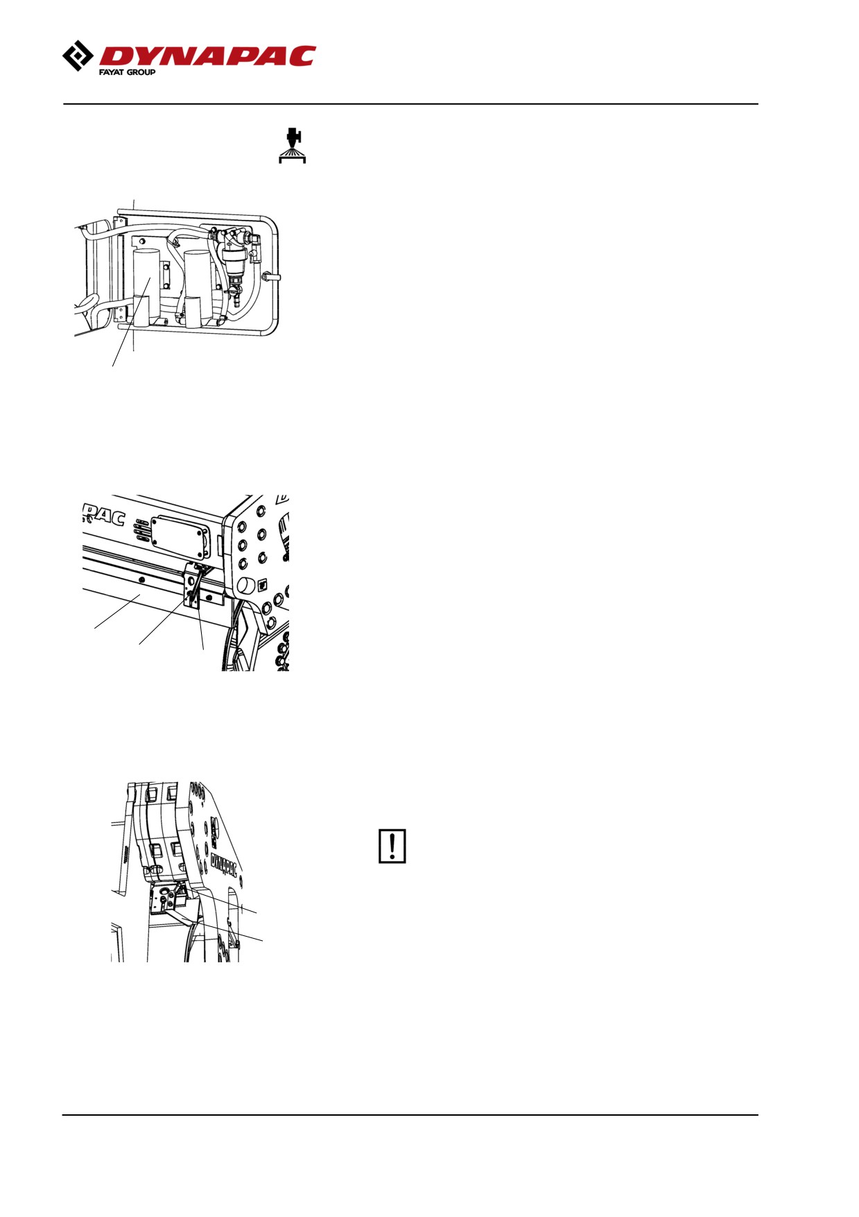
Emergency watering (Accessory) - Extra pump
in pump system
If the water pump stops, an extra pump will keep the
sprinkler system in operation.
Connect the electric cable and water hoses to the
extra pump instead of the standard pump.
The water hoses are connected to the pump with quick
couplings to simplify draining and where appropriate
replacement to a reserve pump (option).
1
Figure. Panel on right side of front
frame
1. Extra pump
Scrapers, spring-action
Check
Make sure that the scrapers are undamaged.
Release with the arm (1).
Loosen the screws (3) to adjust the scraper blade up
2
or down.
3
1
Figure. Outer scrapers
1. Release arm
2. Scraper blade
3. Adjusting screw
Asphalt remnants can accumulate on the scraper and
affect the contact force. Clean when necessary.
The scrapers must be retracted from the drum
during transport driving.
1
2
Figure. Inner scrapers
1. Release arm
2. Lifting handle
98
Maintenance, 10h
Scrapers
Setting - Adjustment
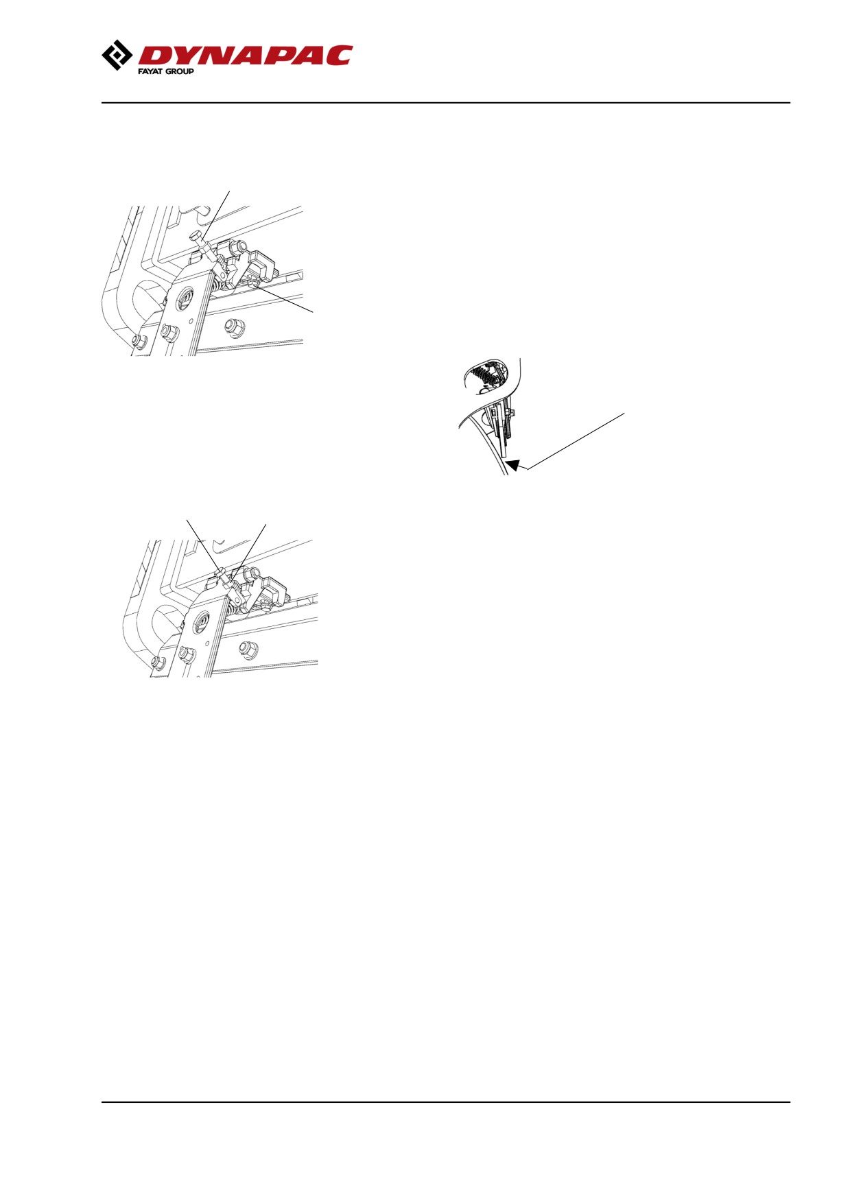
2
Release the retaining unit (1) for the scraper bracket
and unscrew the adjusting screw (2) to release.
Push in the scraper bracket and tighten.
Adjust the screw (2) so that the scraper blade lies
approx. 2 mm (0.08 in) from the drum on the same
side as the screw.
1
Adjust the scraper bracket in or out on the other side
so that there is an equal gap between the scraper
blade and drum, and tighten the retaining unit (1).
1-2 mm
(0.04-0.08 in)
2
3
The adjusting screw (2) is adjusted until the scraper
blade has a gap of approx. 1 mm (0.04 in) to the roller,
or lies loosely on the roller, along its entire length.
Tighten the lock nut (3).
Figure. Scraper setting
1. Retaining unit
2. Adjusting screw
3. Lock nut
99
Maintenance, 10h
100
Maintenance - 50h
Maintenance - 50h
Every 50 hours of operation (Weekly)
Park the roller on a level surface.
The engine must be switched off and the
parking brake activated when checking or
adjusting the roller, unless otherwise specified.
Ensure that there is good ventilation (air
extraction) if the engine is run indoors. Risk of
carbon monoxide poisoning.
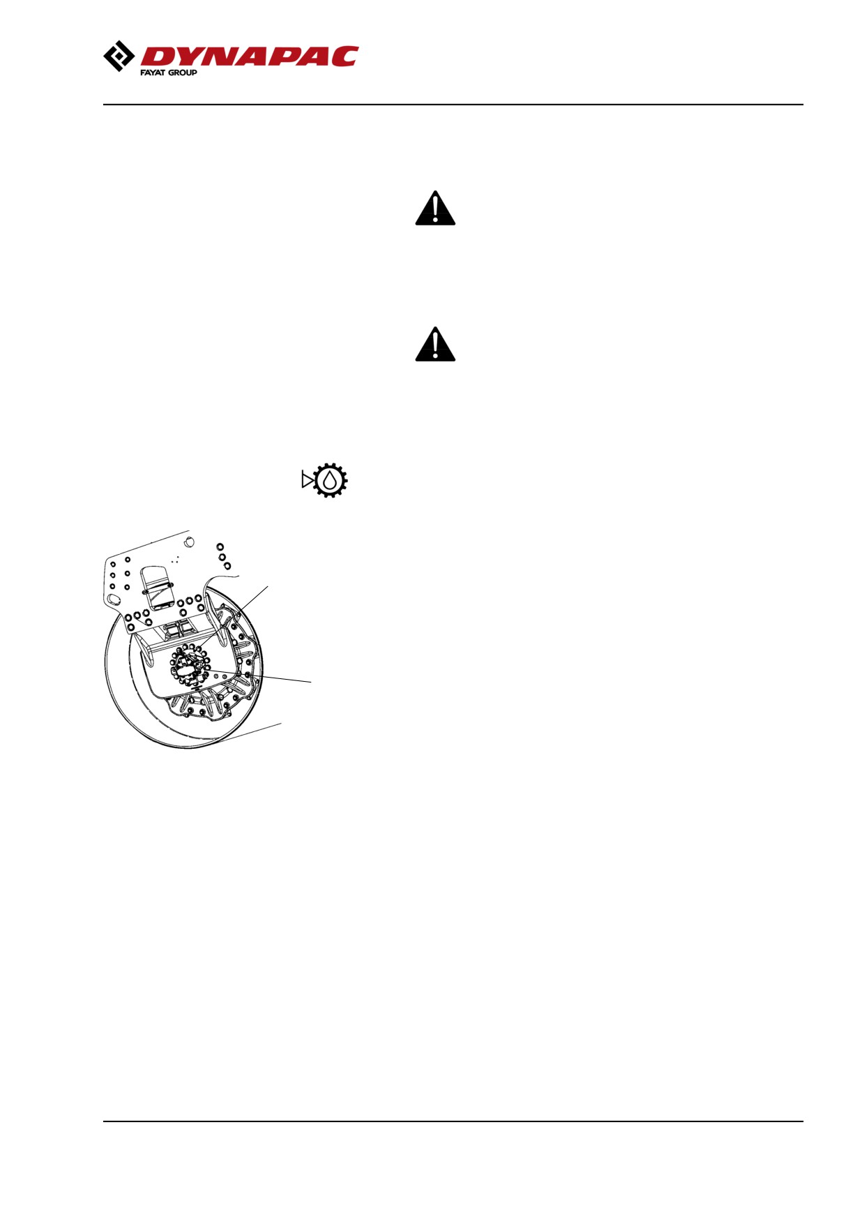
Drum gear - Checking the oil level
Wipe clean the area around the level plug (1) and then
undo the plug.
2
Ensure that the oil level reaches up to the lower edge
of the plug hole.
Replenish the oil to the right level if the level is low.
Use transmission oil, see lubricant specifications.
1
It may be necessary to remove the speed sensor
when filling the front drum.
Clean and refit the plugs.
Fig. Oil level check - drum gear
1. Level plug
2. Filling plug
101
Maintenance - 50h
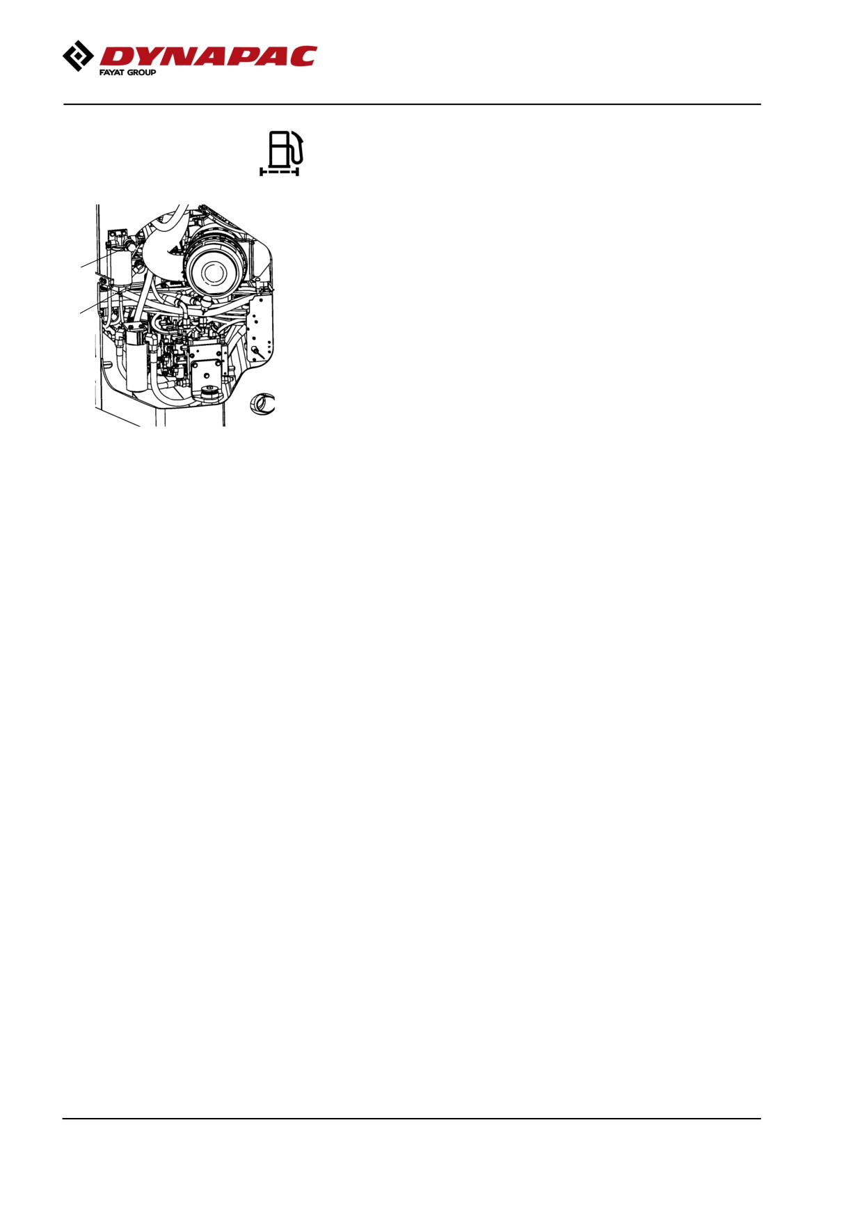
Fuel filter - Draining
Unscrew the drain plug (1) at the bottom of the fuel
filter.
2
With the aid of the secondary hand-operated pump,
1
make certain that all sediment comes out. See
Cummins service manual.
Tighten the drain plug as soon as uncontaminated fuel
runs out.
Figure. Fuel filter
1. Drain plug
2. Hand pump
102
Maintenance measures - 250 h
Maintenance measures - 250 h
Every 250/750/1250/1750
hours of operation (every
3 months)
Park the roller on a level surface.
The engine must be switched off and the
parking brake activated when checking or
adjusting the roller, unless otherwise specified.
Ensure that there is good ventilation (air
extraction) if the engine is run indoors. Risk of
carbon monoxide poisoning.
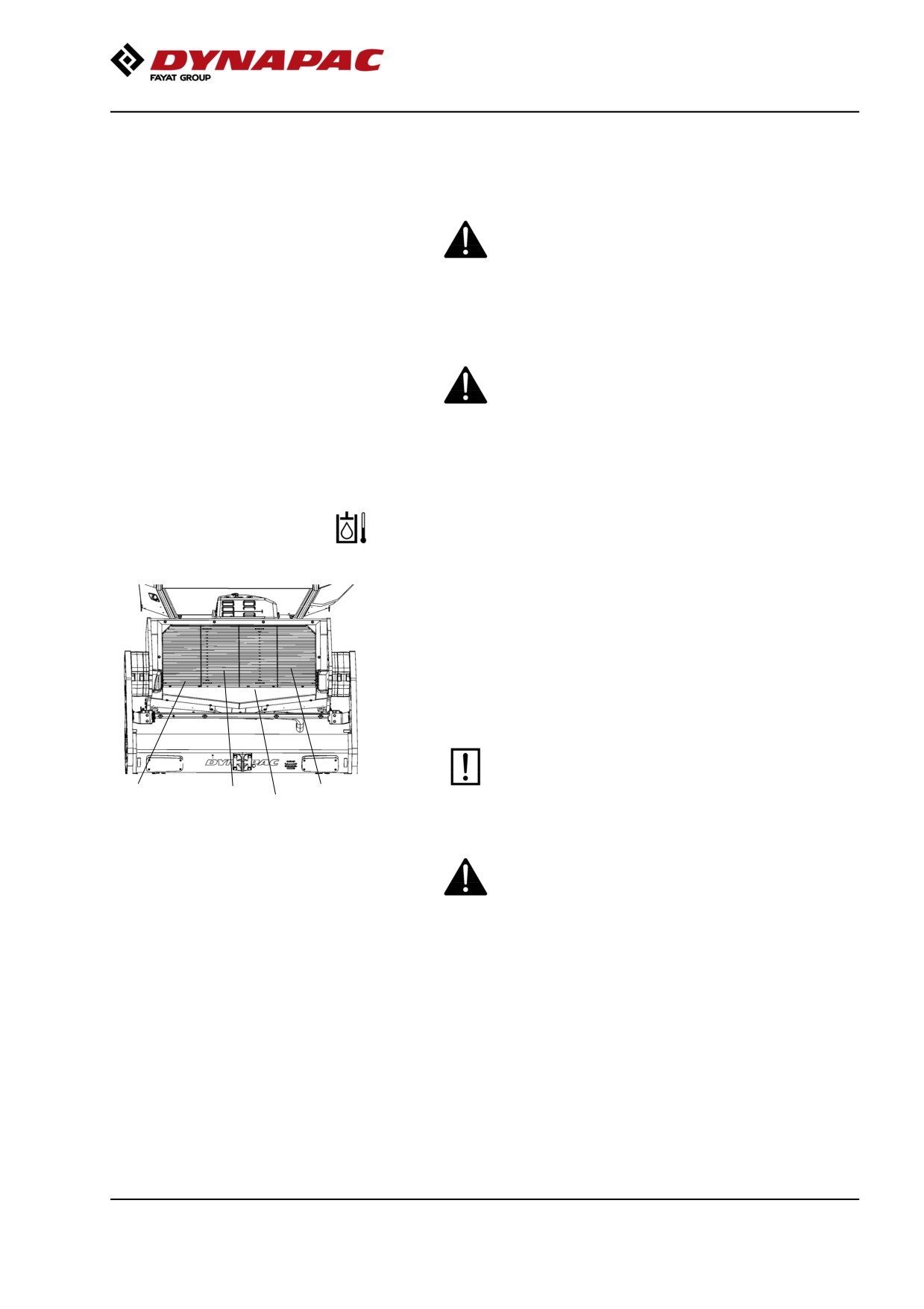
Hydraulic fluid cooler
Checking - Cleaning
The water and hydraulic fluid coolers are accessible
when the cooler grill (4) is removed.
Make sure that the air flow through the cooler is
unobstructed. Dirty coolers are blown clean with
compressed air or washed clean using a
high-pressure water cleaner.
Take care when using a high-pressure water jet.
Do not hold the nozzle too near the cooler.
3
2
1
4
Figure. Cooler
1. Charge air cooler
2. Water cooler
3. Hydraulic fluid cooler
Wear protective goggles when working with
4. Cooler grill
compressed air or high-pressure water jets.
103
Maintenance measures - 250 h
Battery
- Check condition
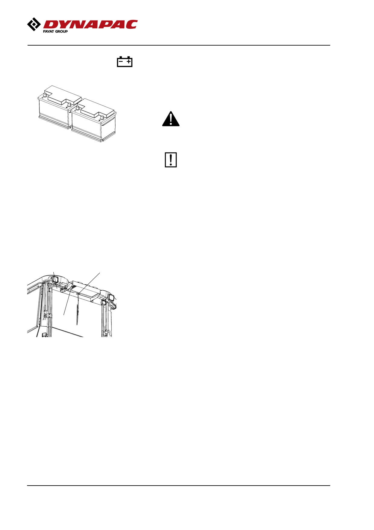
The batteries are sealed and maintenance-free.
Make sure there is no open flame in the vicinity
when checking the electrolyte level. Explosive gas
is formed when the alternator charges the battery.
Figure. Batteries
When disconnecting the battery, always
disconnect the negative cable first. When
connecting the battery, always connect the
positive cable first.
The cable shoes should be clean and tightened.
Corroded cable shoes should be cleaned and greased
with acid-proof Vaseline.
Wipe the top of the battery.
Air conditioning (Optional)
- Inspection
1
2
Inspect refrigerant hoses and connections and make
sure that there are no signs of an oil film that can
indicate a refrigerant leakage.
If there is a signifcant loss of cooling capacity, clean
the condensor element (2) on the rear edge of the cab
roof.
3
Fig. Air conditioning
1. Refrigerant hoses
2. Condensor element
3. Drying filter
104
Maintenance measures - 250 h
Air conditioning (Optional)
Drying filter - Inspection
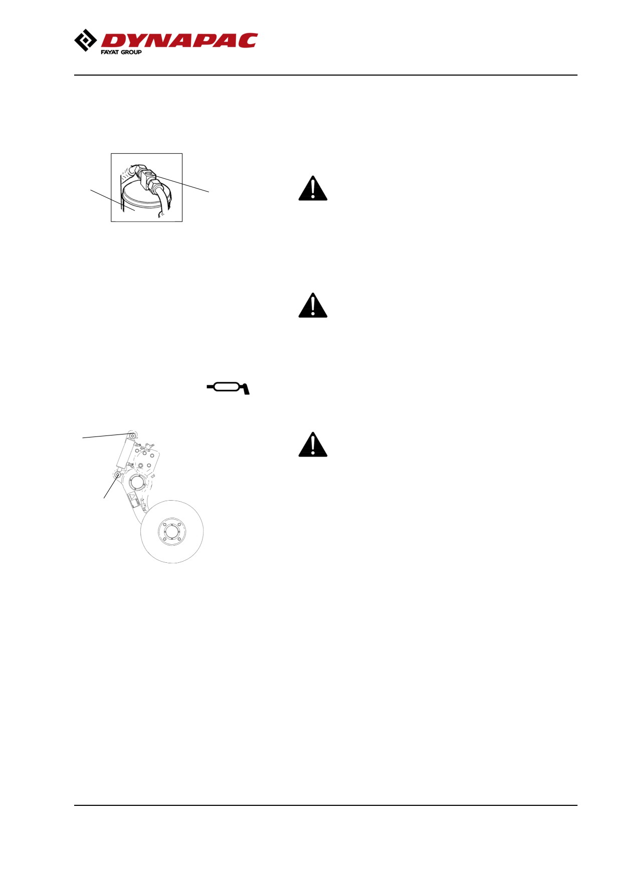
With the unit in operation, check using the sight glass
(1) that bubbles are not visible on the drying filter.
Park the roller on a level surface, chock the wheels
2
and activate the parking brake.
1
Figure. Drying filter
The filter is placed at the top of the rear part of the cab
1. Sight glass
2. Filter holder
roof.
If bubbles are visible through the sight glass, this
indicates that the refrigerant level is too low. Stop the
unit to avoid risking damage. Fill up with refrigerant.
The refrigerant circuit is only to be worked on by
authorized companies.
Edge cutter (Optional)
- Lubrication
Refer to the operation section for information on
2
how to operate the edge cutter.
1
Grease the two points as shown in the figure.
Grease should always be used for lubrication, see the
lubricant specifications.
Grease all bearing points with five strokes of a
Figure. Two grease points for
hand-operated grease gun.
lubricating the edge cutter
105
Maintenance measures - 250 h
106
Maintenance measures - 500 h
Maintenance measures - 500 h
Every 500/1500
hours of operation (every six
months)
Park the roller on a level surface.
The engine must be switched off and the
parking brake activated when checking or
adjusting the roller, unless otherwise specified.
Ensure that there is good ventilation (air
extraction) if the engine is run indoors. Risk of
carbon monoxide poisoning.
Hydraulic fluid cooler
Checking - Cleaning
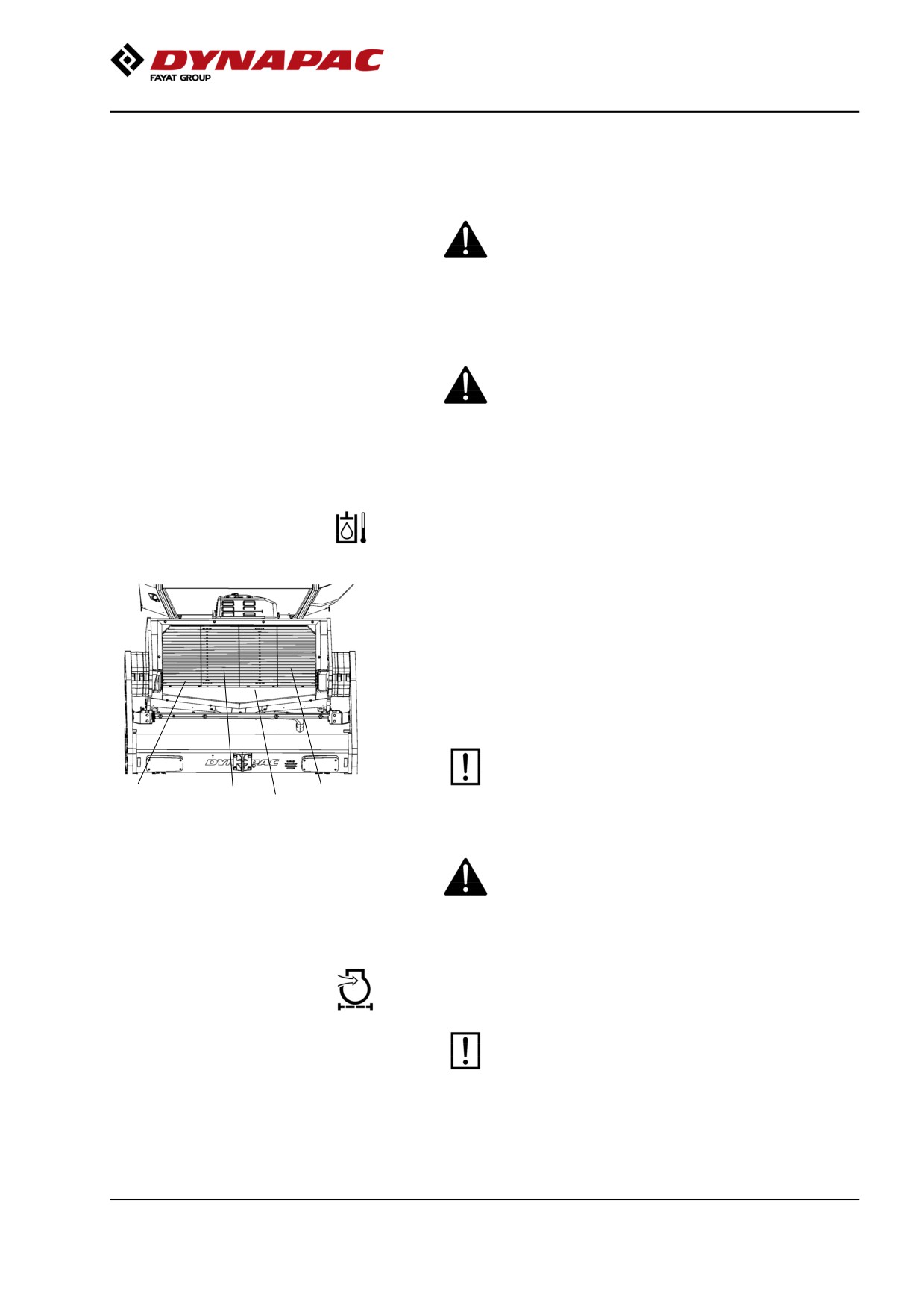
The water and hydraulic fluid coolers are accessible
when the cooler grill (4) is removed.
Make sure that the air flow through the cooler is
unobstructed. Dirty coolers are blown clean with
compressed air or washed clean using a
high-pressure water cleaner.
Take care when using a high-pressure water jet.
Do not hold the nozzle too near the cooler.
3
2
1
4
Figure. Cooler
1. Charge air cooler
2. Water cooler
3. Hydraulic fluid cooler
Wear protective goggles when working with
4. Cooler grill
compressed air or high-pressure water jets.
Air cleaner
Checking - Change the main air filter
Change the air cleaner's main filter when the
warning lamp on the display lights when the
diesel engine is operating at full speed.
107
Maintenance measures - 500 h
2
3
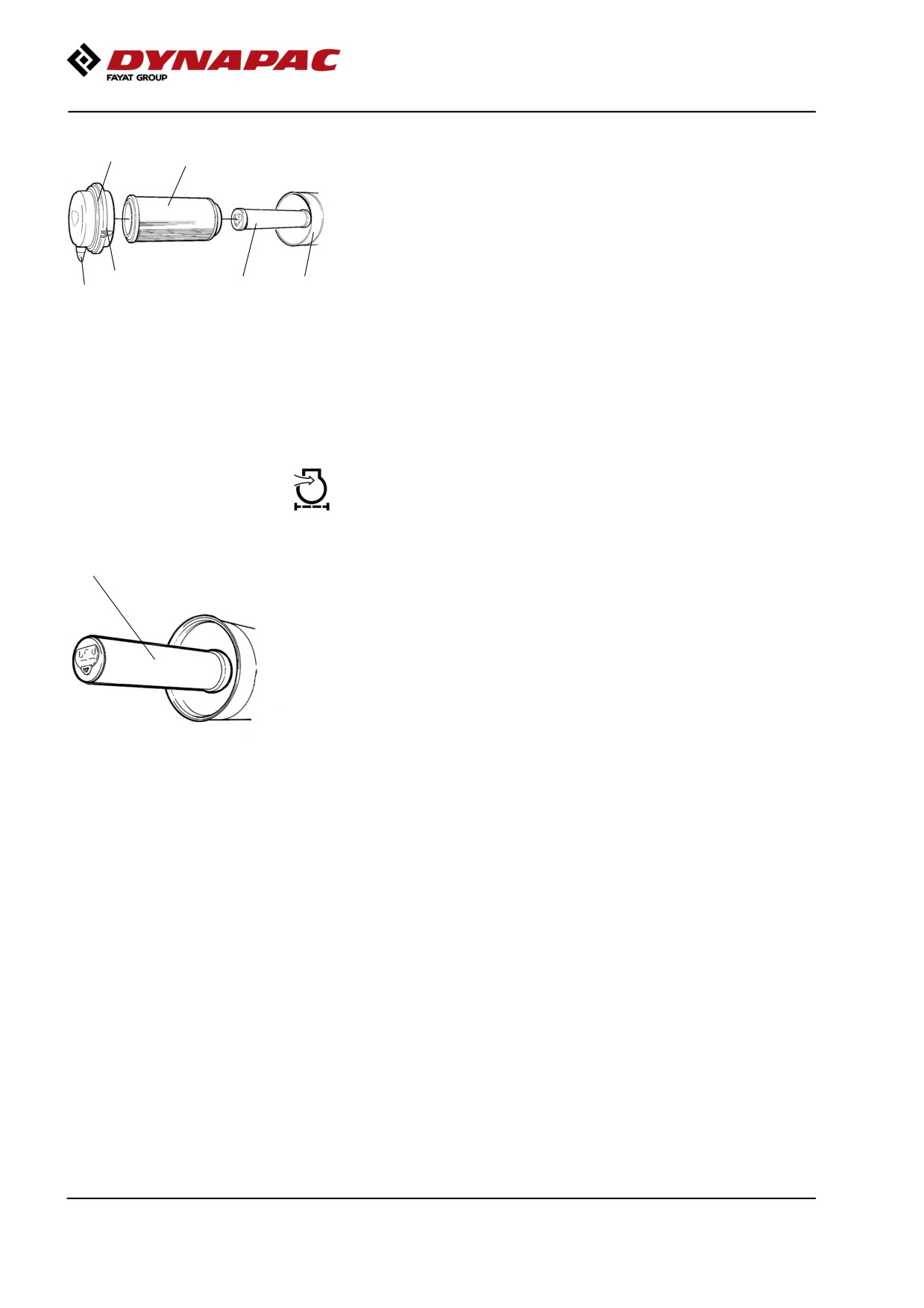
Release the clips (1), pull off the cover (2), and pull out
the main filter (3).
Do not remove the backup filter (4).
Clean the air cleaner if necessary, see section Air
cleaner - Cleaning.
When replacing the main filter (3), insert a new filter
1
4
5
6
and refit the air cleaner in the reverse order.
Fig. Air cleaner
Check the condition of the dust valve (6); replace if
1. Clips
necessary.
2. Cover
3. Main filter
4. Backup filter
When refitting the cover, make sure that the dust valve
5. Filter housing
is positioned downwards.
6. Dust valve
Backup filter - Change
1
Change the backup filter with a new filter after every
second replacement of the main filter.
To change the backup filter (1), pull the old filter out of
its holder, insert a new filter and reassemble the air
cleaner in the reverse order.
Clean the air cleaner if necessary, see section Air
cleaner - Cleaning.
Fig. Air filter
1. Backup filter
108