HAMILTON-T1. Operator's Manual (2022) - page 8

15 Specifications
Parameter
Configuration range
Default setting
Setups
This information applies to the default adult Quick setup configurations.
You can also specify default neonatal settings.
For information about CPR configuration settings, see Table 15-15.
Mode Ctrls
Vt/IBW (Adult/Ped): 5 to 12 ml/kg
Adult/Ped: 8 ml/kg
Vt/Weight (Neonatal): 5 to 12 ml/kg
Neonatal: 5 ml/kg
Vent Status
Oxygen143
22 to 80
40
(%)
PEEP144
1 to 20
8
(cmH2O)
ΔPinsp
1 to 50
10
(cmH2O)
%MinVol high
100 to 250
150
(%)
%MinVol low
25 to 99
50
(%)
RSB high
50 to 150
100
(1 / (l*min))
RSB low
0 to 49
10
(1 / (l*min))
%fSpont145
0 to 99
75
(%)
Connectivity
More
Communication protocol:
GALILEO
Hamilton, GALILEO compatible, Hamilton P2,
Philips VueLink Open, DrägerTestProtocol, Hamil-
ton Block Protocol
143 The low Oxygen setting is always 21%.
144 The low PEEP setting is always 0 cmH2O.
145 The high %fSpont setting is always 100%.
304
English | 10103179/02 USA
Configuration
15
Table 15-15. CPR default settings
Parameter
APVcmv
PCV+
For ranges, see Section 15.6.
Apnea time
10
10
(s)
Oxygen
100
100
(%)
ΔPcontrol
--
15
(cmH2O)
PEEP/CPAP
5
5
(cmH2O)
Plimit
45
45
(cmH2O)
Rate
10
10
(b/min)
TI
1
1
(s)
Vt/IBW
6
--
(ml/kg)
Hamilton Medical | HAMILTON-T1 Operator's Manual
305

15 Specifications
15.10 ASV technical data
Table 15-16. ASV technical data
ASV-related data
Specifications
ASV-related operator settings
%MinVol
25% to 350%
Patient height
Adults: 130 to 250 cm / 50 to 100 in
Pediatric: 30 to 150 cm / 12 to 60 in
Internal calculations
IBW
In kg, calculated based on patient height and
sex (see Section 5.3)
MinVol (target)
In l/min, target minute volume is calculated as:
IBW (in kg) x NormMinVent (in l/kg/min) x
%MinVol/100
where NormMinVent is the normal minute
ventilation from Figure 7-18.
fTotal
In b/min
VDaw
2.2 ml/kg IBW
Vt (target)
MinVol / f(target)
ASV graph
Status of patient (numerical)
fControl, fSpont, ΔPinsp
Graphics display (curve)
fTotal versus Vt, target value, current value,
safety window
Alarms
All alarms are functional except apnea alarms
See Chapter 9
Special
ASV: Cannot meet target alarm
Performance specifications
Response time (90% of steady state)
< 1 min (typical)
306
English | 10103179/02 USA

ASV technical data
15
ASV-related data
Specifications
Overshoot/undershoot
< 25%
Maximum pressure change per breath
3 cmH2O
Settling time
< 120 seconds
Steady state deviation
< 10%
Lung-protective rules
Minimum Vt
4.4 ml/kg x IBW
Maximum Vt depends on
The maximum tidal volume in ASV is the small-
est value of the following conditions:
• V / Pmedian x (P ASV limit - PEEP)
• 15 ml/kg x IBW
• 1.5 x high Vt alarm limit
Maximum machine rate
The maximum rate in ASV is the smallest value
of the following conditions:
• 1 / (minimum inspiratory time + minimum
expiratory time)
• MinVol (target) / Minimum Vt
• 60 b/min
Minimum target rate
7.5 to 15 b/min (depending on IBW)
Minimum ΔPinsp
5 cmH2O above PEEP/CPAP
Maximum ΔPinsp
High Pressure alarm limit - 10 cmH2O - PEEP
Minimum inspiratory time (TI)
0.5 s or RCexp, whichever is longer
Maximum inspiratory time (TI)
IBW = 30 kg: 2 seconds
IBW < 30 kg: 1.5 seconds
Minimum expiratory time (Te)
0.5 s or 2 x RCexp, whichever is longer
Maximum expiratory time (Te)
12 seconds
I:E range
1:4 to 1:1
Hamilton Medical | HAMILTON-T1 Operator's Manual
307

15 Specifications
15.11 Ventilator breathing
system specifications
Table 15-17. Ventilator breathing system specifications
Parameter
Specification
Resistance146
Adult/Ped circuit (ID15 to
≤ 0.06 cmH2O/l/min
ID22, flow of 30 l/min)
Adult/Ped circuit (ID12 to
≤ 0.12 cmH2O/l/min
ID15, flow of 15 l/min)
Neonatal circuit (ID09 to
≤ 0.12 cmH2O/l/min
ID12, flow of 15 l/min)
Compliance146
Adult/Ped circuit (ID15 to
≤ 4.0 ml/cmH2O at 60 cmH2O ± 3 cmH2O
ID22)
Adult/Ped circuit (ID12 to
≤ 4.0 ml/cmH2O at 60 cmH2O ± 3 cmH2O
ID15)
Neonatal circuit (ID09 to
≤ 1.5 ml/cmH2O at 60 cmH2O ± 3 cmH2O
ID12)
Volume146
Adult circuit (ID19)
2.4 l
Neonatal circuit (ID10)
~ 0.9 l
Bacteria filter
Particle size
Captures particles of 0.3 mm (micron) with
> 99.99% efficiency
Resistance
< 2.0 cmH2O at 60 l/min
Flow sensor dead
Adult/pediatric
< 9 ml (single use)
space
< 11 ml (reusable)
Neonatal
< 1.3 ml
146 As tested, the inspiratory limb includes ambient valve, flow sensor, inspiratory filter, inspiratory tubes, and humidifier. It does not
include the heating wire. The expiratory limb includes expiratory tubes, water trap, expiratory valve, and flow sensor.
308
English | 10103179/02 USA

Technical performance data
15
15.12 Technical performance
data
Table 15-18. Technical performance data
Description
Specification
Patient ideal body
3 to 139 kg (6.6 to 306 lb)147
weight (IBW, deter-
mined from Pat.
height setting)
Weight (used for
0.2 to 30 kg (0.44 to 66 lb)
neonatal patients)
Inspiratory pressure
0 to 60 cmH2O
Maximum limited
60 cmH2O
pressure
Maximum working
Adult/Ped: 60 cmH2O (total inspiratory pressure). Ensured through pres-
pressure
sure limiting
Neonatal: 45 cmH2O (limitation depending on frequency)
Maximum inspiratory
260 l/min (120 l/min with 100% O2)
flow
Tidal volume/target
Adult/Ped: 20 to 2000 ml
tidal volume
Neonatal: 2 to 300 ml
Minute volume
Up to 60 l/min
capability
Inspiratory time
0.2 to 3 seconds
(spontaneous breaths)
Minimum expiratory
20% of cycle time; 0.2 to 0.8 seconds
time
Automatic expiratory
Adult/Ped: Fixed at 3 l/min
base flow
Neonatal: Fixed at 4 l/min
Means of inspiratory
Flow trigger control
triggering
Oxygen mixer
± (volume fraction of 2.5% + 2.5% of actual reading)
accuracy
147 Actual patient weight can be much greater (e.g., 300 kg or 661 lb).
Hamilton Medical | HAMILTON-T1 Operator's Manual
309
15 Specifications
Description
Specification
Measuring devices
Continuous oxygen
The delivered oxygen concentration is continuously measured when an
measurement
O2 sensor is enabled.
Type of sensor: Galvanic lead-free O2 sensor
Sensing position:
Inspiratory pneumatics
Measurement, deliv-
18% to 105%
ered oxygen concen-
tration, range:
Response time:
< 45 seconds to reach 90% of final oxygen
concentration
Initialization time
< 40 seconds
(time from turning on
device to operating
performance):
Drift:
< 0.1%/month of sensor output signal at dry
ambient air
Storage temperature:
-20°C to 40°C (-4°F and 104° F)
-20°C to 50°C (-4°F and 122° F), for a maxi-
mum of 1 week
To maximize the shelf life of unused lead-free
galvanic O2 sensors, store them between 15°C
and 25°C (59°F and 77°F).
Storage at higher temperatures will shorten
the life of the lead-free O2 sensor.
Replacement
Every 2 years or when depleted, whichever
comes first
310
English | 10103179/02 USA
Technical performance data
15
Description
Specification
Continuous oxygen
Type of sensor: Galvanic O2 sensor
measurement
Sensing position:
Inspiratory pneumatics
Measurement, deliv-
18% to 105%
ered oxygen concen-
tration, range:
Response time:
< 45 seconds to reach 90% of final oxygen
concentration
Initialization time
< 40 seconds
(time from turning on
device to operating
performance):
Drift:
≤ 1.0% vol. oxygen per month
Storage temperature:
-20°C to 50°C (-4°F to 122°F)
To maximize the shelf life of unused galvanic
O2 sensors, store them between 5°C and 15°C
(41°F and 59°F).
Replacement
Every year or when depleted, whichever comes
first
Pressure and volume
Type:
Differential pressure transducer, variable orifice
measurements
Sensing position:
Patient Y-piece
Measurements:
See Table 15-10
Hamilton Medical | HAMILTON-T1 Operator's Manual
311

15 Specifications
Description
Specification
CO2 measurement
Two types of CO2 sensors are supported: CAPNOSTAT-5 (mainstream)
and LoFlo (sidestream)
Type: CAPNOSTAT 5
Sensing position:
Mainstream
Principle of operation:
Nondispersive infrared (NDIR) technology
Measurements:
See Table 15-10
Rise time:
< 60 ms
Initialization time:
Capnogram displayed in < 15 seconds at an
ambient temperature of 25°C, full specifi-
cations within 2 minutes
Sampling frequency:
100 Hz
CO2 calculation
BTPS
method:
CO2 stability148:
Short-term drift: ≤ 0.8 mmHg over 4 hours
Long-term drift: Accuracy specification main-
tained over 120 hours
CO2 noise (rms):
≤ 0.25 mmHg at 7.5% CO2
Operating condi-
Temperature: 0°C to 45°C (32°F to 113°F)
tions149:
Humidity: 10% to 90% relative humidity, non-
condensing
Pressure (barometric + airway pressure): 400
mmHg to 850 mmHg
Shipment/storage
Temperature: -40°C to 70°C (-40°F to 158°F)
conditions:
Humidity: < 90% relative humidity, noncon-
densing
Pressure (atmospheric): 375 mmHg to
795 mmHg
148 Neither humidity (noncondensing) nor cyclical pressures have any effect on the stated accuracy of the device.
149 The stated operating conditions apply to both continuous and transient operation of the sensor within the limitations specified in
the Intended use.
312
English | 10103179/02 USA

Technical performance data
15
Description
Specification
CO2 measurement
Type: LoFlo
Sensing position:
Sidestream
Principle of operation:
Nondispersive infrared (NDIR) technology
Measurements:
See Table 15-10
Rise time:
200 ms for on-airway adapter kits
Additional 30 ms for sidestream sampling can-
nulas.
Additional 80 ms for extension line and dehu-
midification tubing.
Initialization time:
Capnogram displayed in < 20 seconds at an
ambient temperature of 25°C, full specifi-
cations within 2 minutes
Sampling frequency:
100 Hz
Gas sampling rate:
50 ml/min ±10 ml/min
CO2 calculation
Actual, corrected for temperature and pressure
method:
in the sample cell
CO2 stability148:
Short-term drift: ≤ 0.8 mmHg over 4 hours
Long-term drift: Accuracy specification main-
tained over 120 hours
CO2 noise (rms):
≤ 0.25 mmHg at 5% CO2
Sensing position:
Inside ventilator
Measurements:
See Table 15-10
Operating condi-
Temperature: 0°C to 40°C (32°F to 104°F)
tions149:
Humidity: 10% to 90% relative humidity, non-
condensing
Pressure (barometric + airway pressure):
400 mmHg to 800 mmHg
Shipment/storage
Temperature: -40°C to 70°C (-40°F to 158°F)
conditions:
Humidity: 10% to 90% relative humidity, non-
condensing
Pressure (atmospheric): 400 mmHg to
800 mmHg
Hamilton Medical | HAMILTON-T1 Operator's Manual
313
15 Specifications
Description
Specification
Tests and special
Leak test, flow sensor/circuit/O2 sensor/CO2 sensor zero calibration, O2
functions
enrichment, manual breath, nebulization, leak compensation, com-
munication interface, compensation of breathing circuit resistance and
compliance
Display device
Display of settings, alarms, and monitored data
Type: Color TFT
Size: 640 x 480 pixels, 8.4 in (214 mm) diagonal
Brightness setting for
The range is 10% to 100% brightness. By default, Day = 80%; Night =
display
40%.
Brightness with NVG
The range is 1 to 10. The default is 5.
option
Alarm volume (Loud-
The range is 1 to 10. The default is 5.
ness150)
Sound power level151
51 dB(A) ±3 dB(A)
Sound pressure
43 dB(A) ±3 dB(A)
level151
150 Volume at 1 meter distance from ventilator. A setting of 1 = 62 dB(A), 5 = 76 dB(A), and 10 = 85 dB(A), with accuracy of ±3
dB(A).
151 Per ISO 80601-2-12.
314
English | 10103179/02 USA
Accuracy testing
15
15.12.1 Accuracy testing
Component
Requirement
The ventilator’s parameter and measure-
CO2 level
If CO2 is higher or lower
ment accuracy is tested using an IMT
alarm condi-
than the set alarm limits or
FlowAnalyser. The tolerance intervals for
tion152
the CO2 sensor fails, this
the data generated by the FlowAnalyser
must be detected and the
are as specified below, and are included in
operator informed through
the accuracy information provided in this
an alarm.
manual.
SpO2 level
If SpO2 is higher or lower
alarm condi-
than the set alarm limits or
Table 15-19. Tolerance intervals for accuracy
testing
tion152
the SpO2 sensor fails, this
must be detected and the
Parameter
Tolerance interval of
operator informed through
type
measurement
an alarm.
Volume
≤ 50 ml: ±1%
PEEP
The applied PEEP must be
> 50 ml: ±1.75%
monitored. If it is higher or
lower than the alarm limits,
Pressure
±0.75% or ±0.1 cmH2O,
this must be detected and
whichever is greater
the user informed through
an alarm.
Flow
±1.75% or ±0.5 l/min,
whichever is greater
Pressure
The airway pressure must be
O2
±1%
monitored. If it is higher or
lower than the set alarm
limits, this must be detected
15.12.2 Essential performance
and the operator informed
through an alarm.
Table 15-20. Essential performance
Volume
The applied and expired
Component
Requirement
volumes must be monitored.
Gas supply
Gas supply failure must be
If they are higher or lower
failure
detected and the operator
than the set alarm limits,
informed.
this must be detected and
the operator informed
Oxygen level
If O2 is higher or lower than
through an alarm.
alarm condi-
the set alarm limits or the
tion
O2 sensor fails, this must be
Disconnection
Any disconnection of the
detected and the operator
breathing circuit must be
informed through an alarm.
detected and the operator
informed through an alarm.
Obstruction
Any obstruction must be
detected and the operator
informed through an alarm.
152 If option is installed.
Hamilton Medical | HAMILTON-T1 Operator's Manual
315
15 Specifications
Component
Requirement
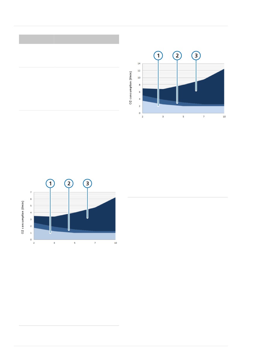
Figure 15-4. Oxygen consumption as a function
of minute volume, oxygen set to 100%
Electrical
An electrical supply failure
supply failure
must be detected and the
operator informed.
Internal elec-
The remaining battery
trical power
capacity must be monitored
source nears
and qualitatively indicated.
depletion
At least 5 minutes prior to
depletion, an alarm must be
issued.
MinVol (l/min)
15.12.3 Estimated oxygen consump-
tion relative to minute volume
1
Oxygen consumption of the device. This
accounts for base flow
The following graphs show oxygen
consumption as a function of minute
2
Compressible volume in the breathing cir-
volume.
cuit.
The compressible volume is a significant
Figure 15-3. Oxygen consumption as a function
factor that must be taken into account for
of minute volume, oxygen set to 60%
smaller patients due to smaller tidal
volumes. See Section 3.4.2.1.
3
Oxygen volume delivered to patient.
MinVol (l/min)
1
Oxygen consumption of the device. This
accounts for base flow
2
Compressible volume in the breathing cir-
cuit.
The compressible volume is a significant
factor that must be taken into account for
smaller patients due to smaller tidal
volumes. See Section 3.4.2.1.
3
Oxygen volume delivered to patient.
316
English | 10103179/02 USA

15
Functional description of ventilator system
15.13 Functional description of
When a condition is critical enough to
possibly compromise safe ventilation, the
ventilator system
HAMILTON-T1 is placed into the Ambient
state. The inspiratory channel and expira-
The HAMILTON-T1 is an electronically-
tory valves are opened, letting the patient
controlled pneumatic ventilation system
inspire room air through the inspiratory
with an integrated air compressing
channel and exhale through the expiratory
system. It runs on AC or DC power with
valve.
battery backup to protect against power
failure or unstable power and to facilitate
The HAMILTON-T1 has several means to
intra-hospital transport.
ensure that safe patient or respiratory
pressures are maintained. The maximum
The user provides inputs to the
working pressure is ensured by the high
HAMILTON-T1 microprocessor system
pressure alarm limit. If the set high pres-
through a touch screen, keys, and a press-
sure limit is reached, the ventilator cycles
and-turn knob. These inputs become
into exhalation. The ventilator pressure
instructions for the HAMILTON-T1’s pneu-
cannot exceed 60 cmH2O.
matics to deliver a precisely controlled gas
mixture to the patient. The ventilator
receives inputs from the proximal flow
15.13.1 Gas supply and delivery
sensor and other sensors within the venti-
lator. Based on this monitored data, the
The HAMILTON-T1 uses room air and
ventilator adjusts gas delivery to the
high- or low-pressure oxygen (Figure
15-5). The use of medical oxygen is
patient. Monitored data is also displayed
mandatory. Air enters through a fresh gas
by the graphical user interface.
intake port and is compressed together
The ventilator’s microprocessor system
with the oxygen by the blower. Oxygen
controls gas delivery and monitors the
enters through a high153- or low154-pres-
patient. The gas delivery and monitoring
sure inlet.
functions are cross-checked by an alarm
controller. This cross-checking helps mini-
Figure 15-5. Gas delivery in the HAMILTON-T1
mize the possible hazards of software fail-
HAMILTON-T1
ure.
High-pressure
A comprehensive system of visual and
oxygen*
O2 mixer valve
Breathing circuit
audible alarms helps ensure the patient’s
Low-pressure
oxygen*
safety. Clinical alarms can indicate an
Flow sensor
abnormal physiological condition. Techni-
Air
Blower
cal alarms, triggered by the ventilator’s
self-tests including ongoing background
checks, can indicate a hardware or soft-
Expiratory valve
Patient
ware failure. In the case of some technical
To room air
alarms, a special safety ventilation ensures
basic minute ventilation while giving the
* only one oxygen source required
operator time for corrective actions.
153 High-pressure oxygen: Maximum allowed pressure is 600 kPa.
154 Low-pressure oxygen: Maximum allowed pressure is 600 kPa, maximum allowed flow 60 l/min.
Hamilton Medical | HAMILTON-T1 Operator's Manual
317
15 Specifications
Within the ventilator, the gas enters the
15.13.2 Gas monitoring with the flow
ventilator’s pneumatic system. If high-
sensor
pressure oxygen is supplied, a mixer valve
provides for the operator-set concentra-
The HAMILTON-T1 accurately measures
tion. If low-pressure oxygen is supplied,
flow, volume, and pressure in the patient’s
the delivered oxygen concentration is
airway with the Hamilton Medical flow
determined by the flow of the oxygen
sensor. This proximal flow sensor lets the
source.
ventilator sense even weak patient breath-
ing efforts. Between its highly sensitive
Gas is supplied to the patient through the
flow trigger and fast response time, the
blower. The microprocessor controls the
ventilator helps minimize the patient’s
speed of the blower and the length of
work of breathing.
time it runs to meet the user settings.
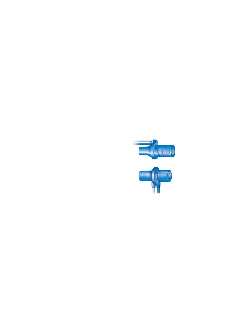
The flow sensor contains a thin membrane
The ventilator delivers gas to the patient
within the outer housing and has a pres-
through the inspiratory limb breathing cir-
sure port on either side. The membrane
cuit parts, which may include one or more
allows bidirectional flow through its vari-
of the following: inspiratory filter, flex
able orifice.
tubes, humidification system, water traps,
Adult/Ped
Y-piece, and flow sensor. An internal
pneumatic nebulizer supplies the nebulizer
flow.
Gas exhaled by the patient passes through
the expiratory limb breathing circuit parts,
Neonatal
which includes one or more of the follow-
ing: flex tubes, flow sensor, Y-piece, and
expiratory valve set. Gas is vented through
the expiratory valve housing such that no
exhaled gas comes into contact with any
internal components of the ventilator. The
The area of the orifice changes depending
expiratory valve is heated to reduce the
on the flow rate. It opens progressively as
possibility of rainout in the expiratory limb.
the flow increases, creating a pressure
drop across the orifice. The pressure dif-
Measurements taken at the flow sensor
ference is measured by a high-precision
are used in the pressure, flow, and volume
differential pressure sensor inside the
measurements.
ventilator. The pressure difference varies
with flow (relationship determined during
The ventilator monitors the oxygen con-
flow sensor calibration), so the patient’s
centration of the gas to be delivered to
flow is determined from the pressure
the patient using a galvanic O2 sensor.
drop. The ventilator calculates volume
The galvanic O2 sensor generates a volt-
from the flow measurements.
age proportional to the partial pressure of
oxygen in the delivered gas.
The flow sensor is highly accurate even in
the presence of secretions, moisture, and
The operations of the blower and expira-
nebulized medications. The ventilator
tory valve are coordinated to maintain
flushes the sensing tubes with mixed
system pressure levels.
gases (rinse flow) to prevent blockage.
318
English | 10103179/02 USA
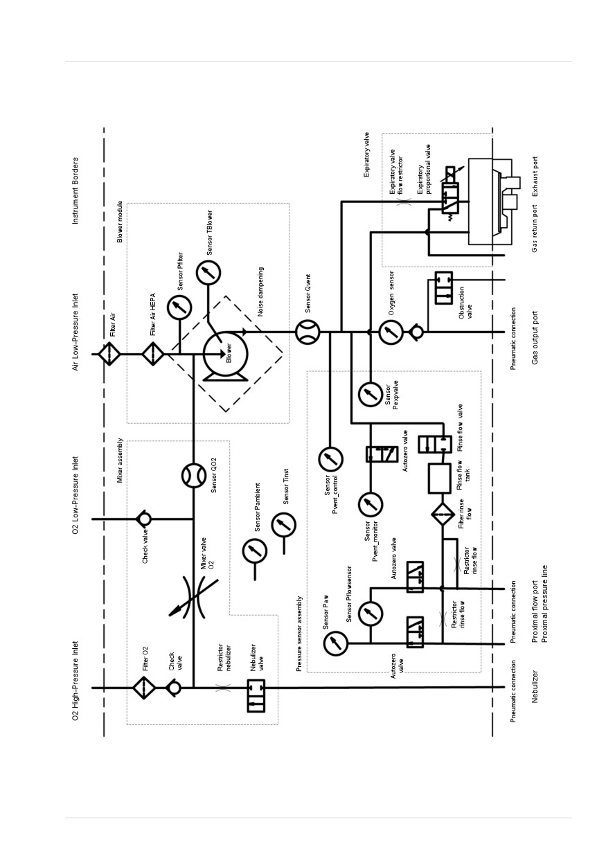
Pneumatic diagram
15
15.13.3 Pneumatic diagram
Hamilton Medical | HAMILTON-T1 Operator's Manual
319
15 Specifications
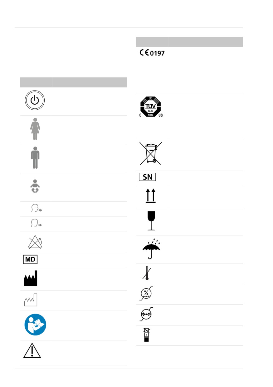
15.14 Symbols used on device
Symbol
Definition
labels and packaging
CE Marking of Conformity,
seal of approval guaranteeing
Table 15-21. Symbols used on device, device
that the device is in confor-
labels, and packaging
mance with the Council Direc-
Symbol
Definition
tive 93/42/EEC concerning
medical devices
Power/Standby key
The TÜV NRTL mark with the
indicators “C“ and “US“
means that the product com-
Female patient
plies with Canadian require-
ments and the requirements of
US authorities for safety.
Dispose according to Council
Male patient
Directive 2002/96/EC or WEEE
(Waste Electrical and Electronic
Equipment)
Neonatal patient
SN
Serial number
This way up at transport and
storage
To patient inspiratory port
Fragile, handle with care at
From patient expiratory port
transport and storage
Alarm Off
Keep dry at transport and
storage
Medical Device
Temperature limitations at
Manufacturer
transport and storage
Humidity limitations at trans-
Date of manufacture
port and storage
Atmospheric pressure limita-
Refer to the operator’s manual
tions at transport and storage
for complete information.
Stacking limitations at trans-
port and storage
Symbol for “Caution”. Applied
parts not protected against
defibrillation.
320
English | 10103179/02 USA
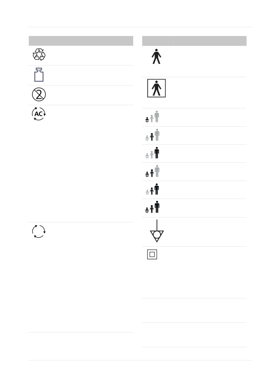
Symbols used on device labels and packaging
15
Symbol
Definition
Symbol
Definition
Recyclable material
Type B applied part (classifica-
tion of medical electrical
equipment, type B, as specified
Mass
by IEC 60601-1)
Type BF applied part (classifica-
tion of medical electrical
Single use
equipment, type BF, as speci-
fied by IEC 60601-1)
Autoclavable.
Applicable to neonatal patient
Autoclavable parts can be used
group
inside an autoclave (for exam-
ple, a steam autoclave) with-
Applicable to pediatric patient
out damage. These parts with-
group
stand temperatures up to
Applicable to adult patient
approximately 134°C. The cor-
group
rect way to reprocess auto-
clavable parts is described in
Applicable to neonatal/pedi-
the Reprocessing Guide pro-
atric patient groups
vided by the manufacturer.
Applicable to pediatric/adult
Parts that Hamilton Medical
patient groups
terms as autoclavable can
undergo autoclaving with
Applicable to all patient
steam sterilization without
groups
damage.
Terminal for the connection of
Reusable.
a potential equalization con-
A reusable part is a medical
ductor.
device or part of a medical
device that can be reused if it
Indicates the degree of protec-
undergoes some sort of repro-
tion against electric shock
cessing between use on differ-
according to IEC 60601-1.
ent patients. The correct way
Class II devices have double or
to reprocess reusable parts is
reinforced insulation, as they
described in the Reprocessing
have no provision for protec-
Guide provided by the manu-
tive grounding.
facturer.
IP24
Protected against splashing
Parts that Hamilton Medical
water and solid particles larger
terms as reusable cannot be
than 12.5 mm.
autoclaved with steam sterili-
zation.
IP54
Protected from water spray
from any direction, and from
limited dust ingress.
Hamilton Medical | HAMILTON-T1 Operator's Manual
321

15 Specifications
Symbol
Definition
15.15 Standards and approvals
HAMILTON-T1 poses unac-
The HAMILTON-T1 was developed in
ceptable risks to the patient,
accordance with pertinent international
medical staff, or other persons
standards and FDA guidelines.
within the MR environment.
The ventilator is manufactured within an
Chinese RoHS
EN ISO 13485 and EN ISO 9001, Council
Directive 93/42/EEC, Annex II, Article 3
Authorized representative in
certified quality management system.
the European Community/
The ventilator meets the Essential Require-
European Union
ments of Council Directive 93/42/EEC,
Federal Communications Com-
Annex I.
mission (FCC) Licensing
Where standards are mentioned, the
HAMILTON-T1 complies with the versions
Near Field Communication
listed in Table 15-23.
The ventilator meets relevant parts of the
The RCM (Regulatory Compli-
following standards, listed in Table 15-22.
ance Mark) indicates a device’s
compliance with applicable
Table 15-22. Standards
ACMA (Australian Communi-
cations and Media Authority)
IEC 60601-1
Medical electrical equip-
technical standards for
ment, Part 1: General
telecommunications, radio
requirements for basic safety
communications, or broadcast-
and essential performance.
ing equipment.
The device classification is:
Class II, Type BF applied part
(ventilator breathing system,
VBS, CO2 sensor including
Japan only. Ministry of Internal Affairs and
CO2 module connector, and
Communications Approval Label
SpO2 sensor including SpO2
adapter), continuous opera-
tion
IEC
Medical electrical equipment
60601-1-2
- Part 1-2: General require-
ments for basic safety and
essential performance.
• Collateral standard: Elec-
tromagnetic disturbances
• Requirements and tests
322
English | 10103179/02 USA
Standards and approvals
15
IEC
Medical electrical equipment
EN ISO
Medical electrical equipment
60601-1-10
- Part 1-10: General require-
80601-2-55
- Part 2-55: Particular
ments for basic safety and
requirements for the basic
essential performance.
safety and essential perfor-
mance of respiratory gas
Collateral standard: Require-
monitors
ments for the development
of physiologic closed-loop
MIL-STD-461F
Control of electromagnetic
controllers
interference
IEC
Medical electrical equipment
MIL-
Low pressure (altitude)
60601-1-12
- Part 1-12: General require-
STD-810G
ments for basic safety and
essential performance.
EN 1789
Medical vehicles and their
equipment - Road ambu-
Collateral standard: Require-
lances
ments for medical electrical
equipment and medical
EN 794-3
Lung ventilators - Part 3:
electrical systems intended
Particular requirements for
for use in the emergency
emergency and transport
medical services environ-
ventilators
ment
RTCA-DO
Environmental Conditions
ISO
Medical electrical equipment
160G
and Test Procedures for Air-
80601-2-12
- Part 2-12: Particular
borne Equipment
requirements for the basic
safety and essential perfor-
Table 15-23. Standards and approvals, valid
mance of critical care venti-
versions
lators
CAN/CSA-
Medical electrical equip-
IEC 60601-1:2005/A1:2012
C22.2 No.
ment: General requirements
ANSI/AAMI ES60601-1:2005/(R)2012
60601.1
for safety
CAN/CSA-C22.2 No. 60601-1:14
ANSI/AAMI ES
Medical electrical equipment
60601-1
- Part 1: General require-
IEC 60601-1-2:2014
ments for basic safety and
ISO 80601-2-12:2011 + Cor.:2011
essential performance
ISO 80601-2-55:2018
EN ISO
Anaesthetic and respiratory
5356-1
equipment - conical connec-
IEC 61000-3-2:2005
tors - Part 1: Cones and
IEC 61000-3-3:2008
sockets
IEC 61000-4-2:2008
EN ISO 5359
Low-pressure hose assem-
blies for use with medical
IEC 61000-4-3:2006 + A1:2007+A2:2010
gases
IEC 61000-4-4:2004
IEC 61000-4-5:2005
Hamilton Medical | HAMILTON-T1 Operator's Manual
323
15 Specifications
IEC 61000-4-6:2003+A1:2004+A2:2006
15.16 Disposal and year of
IEC 61000-4-8:2009
manufacture
IEC 61000-4-11:2004
Disposal
EN ISO 5359:2008 + A1: 2011
The device must be disposed of according
to your institution's protocols and Direc-
EN ISO 13485:2016
tive 2002/96/EC.
IEC 60950-1:2013
All parts removed from the device must be
ISO 15883-1:2006+A1:2014
considered contaminated, and pose infec-
tion risk.
ISO 15883-2:2006
Dispose of all parts removed from the
ISO 15883-3: 2006
device according to your institution’s pro-
ISO 15883-4:2008
tocol. Follow all local, state, and federal
regulations with respect to environmental
ISO 11607-1: 2006 + AMD1:2014
protection, especially when disposing of
EN ISO 9001:2008
the electronic device or parts of it (for
example, O2 sensor, batteries).
EN ISO 5356-1:2015
Year of manufacture
ISO 4135:2001
The year of manufacture is shown on the
EN 794-3:1998 + A2:2009
serial number label on the HAMILTON-T1
EN 1789:2007 + A1:2010
ventilation unit.
MIL-STD-461F
MIL-STD-810G
RCTA-DO 160 G
324
English | 10103179/02 USA
Warranty
15
15.17 Warranty
accordance with the instructions fur-
nished by Hamilton Medical and by a
LIMITED WARRANTY
Hamilton Medical representative.
2.
If replacements and/or repairs have
THE WARRANTY DESCRIBED IN THIS
not been performed by authorized or
AGREEMENT IS IN LIEU OF ANY AND ALL
properly trained personnel.
OTHER WARRANTIES, EXPRESS OR
IMPLIED, INCLUDING IMPLIED WAR-
3.
If no evidence is present that the
RANTIES OF MERCHANTABILITY AND FIT-
occurrence of damage/ repair hap-
NESS FOR A PARTICULAR PURPOSE.
pened within the certified warranty
HOWEVER, IMPLIED WARRANTIES ARE
period.
NOT DISCLAIMED DURING THE PERIOD OF
4.
If the serial number has been altered,
THIS LIMITED WARRANTY.
effaced or removed and there is no
Hamilton Medical guarantees its products
bill of sale or evidence to verify the
to be shipped free from defects in material
product’s purchase date.
and workmanship.
5.
If the defects arise from misuse, negli-
gence, or accidents or from repair,
The warranty does not include disposable
adjustment, modification or replace-
items. Disposable items and consumable
ment made outside Hamilton Medi-
products are considered to be of single
cal’s factories or other than an autho-
use or of limited use only and must be
rized service center or authorized ser-
replaced regularly as required for proper
vice representative.
operation of the product following the
operator’s manual.
6.
If the product has been modified, or
in any nature altered without prior
Hamilton Medical shall have no obliga-
written authorization from Hamilton
tions nor liabilities in connection with the
Medical.
product other than what is specified
7.
If yearly maintenance is not per-
herein, including without limitation, obli-
formed.
gations and/ or liabilities for alleged negli-
gence, or for strict liability.
8.
If the product is or has been used in
any way that is not specified under
In no event shall the company be liable for
“Intended Use” (see “General cau-
incidental or consequential damages,
tions and notes”).
either direct or contingent.
9.
If the product has been used by any-
This Limited Warranty shall be void and
one but properly trained personnel
not apply:
under the supervision of a physician.
1. If the product has not been installed
Replacements and/or repairs furnished
and connected by an authorized local
under this Limited Warranty do not
representative of Hamilton Medical in
carry a new warranty, but carry only
the unexpired portion of the original
Limited Warranty. The warranty of
repaired and/or replaced components
does not exceed the Limited Warranty
of the device.
Hamilton Medical | HAMILTON-T1 Operator's Manual
325
15 Specifications
To obtain service under this Limited War-
ranty, claimant must promptly notify the
country’s sales partner of Hamilton Medi-
cal regarding the nature of the problem,
serial number and the date of purchase of
the Product.
Except as stated above, Hamilton Medical
shall not be liable for any damages, claims
or liabilities including, but not limited to,
personal bodily injury, or incidental, conse-
quential, or special damages. Nor will
Hamilton Medical be liable for any dam-
ages, claims or liabilities including, but not
limited to, personal bodily injury, or inci-
dental, consequential, or special damages
resulting from misuse of the device or fail-
ure to comply with any of the provisions
made in this manual.
The general terms and conditions of
Hamilton Medical shall be applicable. This
agreement shall be governed by and con-
strued in accordance with the laws of
Switzerland and may be enforced by
either party under the jurisdiction of the
court of Chur, Switzerland.
326
English | 10103179/02 USA
Glossary
(S)CMV+
backup
See APVcmv
Apnea backup ventilation
alarm lamp
backup buzzer
Lamp on top of the ventilator that
A buzzer that sounds for at least 2
lights in the color corresponding to
minutes in certain conditions; also
the active alarm
functions as a backup for the ventila-
tor loudspeaker
Alarm Off symbol
Displayed when the associated alarm
base flow
limit is disabled (set to Off)
A continuous and constant gas flow
from the inspiratory outlet to the
apnea
expiratory outlet
Cessation of breathing
breathing circuit
APRV
Breathing limbs and components
Airway pressure release ventilation, a
used to deliver respiratory gases to
ventilation mode
the patient
APVcmv
BTPS
Adaptive pressure ventilation with
Body temperature, barometric pres-
controlled mandatory ventilation, a
sure at sea level, saturated with water
ventilation mode; can also be shown
vapor
as (S)CMV+ (configurable)
CE
APVsimv
A certification mark that indicates
Adaptive pressure ventilation with
compliance with the Medical Device
synchronized intermittent mandatory
Directive, 93/42/EEC
ventilation, a ventilation mode; can
also be shown as SIMV+ (config-
control
urable)
A virtual dial, slider or other input
icon on the display that allows you to
ASV
specify the value of a setting
Adaptive support ventilation mode.
ASV adjusts pressure and rate on a
control setting, control parameter
breath-by-breath basis, taking into
Any setting that the ventilator uses as
account changing patient conditions
an input for the delivered ventilation
and applying lung-protective strate-
therapy. For example, PEEP/CPAP,
gies to meet the targets.
IBW, or Weight, Vt, and so on. Note
that some control settings, such as
ASV Graph
IBW, are not directly specified by the
An Intelligent panel that shows ASV
user.
target and patient data graphically,
available in ASV mode
CPR ventilation
CPR ventilation allows you to to con-
AutoPEEP
tinue respiration during the adminis-
Unintended positive end-expiratory
tration of cardiopulmonary resuscita-
pressure, a monitored parameter
tion.
Hamilton Medical | HAMILTON-T1 Operator's Manual
327
Glossary
CSA
maneuvers, and special function uses
Canadian Standards Association
that have occured since the ventilator
was turned on
Cstat
Static compliance, a monitored para-
Exp Flow
meter
Peak expiratory flow, a monitored
parameter
Driving pressure (ΔP)
A calculated value showing the ratio
ExpMinVol
of tidal volume to static compliance,
Expiratory minute volume, a moni-
which reflects the difference between
tored parameter and alarm setting; in
Pplateau and PEEP total; can provide
the Vent Status panel, ExpMinVol is
information to help optimize ventila-
the percentage of normal minute
tion for ARDS patients
ventilation based on IBW
DuoPAP
fControl
Duo positive airway pressure, a venti-
Mandatory breath frequency, a moni-
lation mode
tored parameter
Dynamic Lung
FDA
Intelligent panel that graphically rep-
United States Food and Drug Admin-
resents tidal volume, lung compli-
istration
ance, resistance, and patient trigger-
ing in real time
FetCO2
Fractional end-tidal CO2 concentra-
EMC
tion, a monitored parameter
Electromagnetic compatibility
Flow (in nCPAP/nCPAP-PC)
EMI
In the neonatal nCPAP and nCPAP-PC
Electromagnetic interference
modes, monitored parameter that
measures and displays the current
EN
flow; the upper (high) limit is control-
European norm, a European standard
led by the Flow alarm
ETS
fSpont
Expiratory trigger sensitivity is the per-
Spontaneous breathing frequency, a
cent of peak inspiratory flow at which
monitored parameter
the ventilator cycles from inspiration
to exhalation. Increasing the ETS
fTotal
setting results in a shorter inspiratory
Total breathing frequency, a moni-
time. The ETS setting lets you match
tored parameter and alarm setting
the inspiratory time of pressure-sup-
ported breaths to the patient´s neural
HEPA
High efficiency particle air filter
timing.
event log
HiFlowO2
High flow oxygen therapy
A record of clinically relevant ventila-
tor occurrences, including alarms,
settings changes, calibrations,
328
English | 10103179/02 USA
Glossary
HME, HMEF
IRV
Heat and moisture exchanger (artifi-
Inverse ratio ventilation: the set
cial nose), heat and moisture
expiratory time is less than the
exchanging filter
inspiratory time
HPO
ISO
High-pressure oxygen
International Organization for Stan-
dardization
I:E
Ratio of inspiratory time to expiratory
loudness
time, a setting, timing parameter,
Sets the volume for the audible venti-
and monitored parameter
lator alarms
IBW
LPO
Ideal body weight, a calculated value
Low-pressure oxygen
for adult and pediatric patients based
LSF
on the patient's sex and height; used
Least squares fitting method; a math-
as the basis for initial settings of vari-
ematical procedure for finding the
ous parameters
best fitting curve for a given set of
ID
points by minimizing the sum of the
Inner diameter
squares of the offsets of the points
from the curve
IEC
International Electrotechnical Com-
mandatory breath
mission
The start of inspiration (triggering) is
determined by the ventilator or the
Insp Flow
patient. The end of inspiration
Peak inspiratory flow, a monitored
(cycling) is determined by the ventila-
parameter
tor.
inspiratory pressure
manual breath
The total inspiratory pressure to be
A user-triggered mandatory breath
applied during ventilation. In some
started by pressing the Manual
modes this is the sum of the pressure
breath key
control + PEEP/CPAP
MinVol
Intelligent Panel
Minute volume, a calculated and
A type of graphic display on the
monitored parameter used in ASV
ventilator
mode; based on the operator-set
%MinVol, the ventilator calculates
IntelliTrig
the target MinVol in l/min, then mea-
Intelligent trigger, a feature that
sures and displays this value in the
ensures that the set trigger sensitivity
ASV Graph
can trigger a breath independent
from leakage and breath pattern
MVLeak
Total minute volume leakage;
MVLeak shows VLeak * frequency
(respiratory rate)
Hamilton Medical | HAMILTON-T1 Operator's Manual
329
Glossary
MVSpont
Pat. height
Spontaneous expiratory minute
Patient height; a control setting used
volume, a monitored parameter
to compute the patient’s ideal body
weight (IBW) in calculations for ASV
nCPAP
and startup settings
Neonatal-only ventilation mode that
applies CPAP over a nasal interface
patient group
(mask or prongs)
A control setting used to define initial
startup settings for the patient;
nCPAP-PC
options are Adult/Ped (adult and
Neonatal-only ventilation mode that
pediatric patients) and Neonatal
delivers, in addition to the set CPAP,
intermittent, time-cycled, and pres-
PCV+
sure-controlled breaths
Pressure controlled ventilation, a
ventilation mode
NIST
Noninterchangeable screw thread, a
PEEP/CPAP
standard for high-pressure gas inlet
PEEP (positive end-expiratory pres-
fittings
sure) and CPAP (continuous positive
airway pressure), a control setting
NIV
and monitored parameter; PEEP and
Noninvasive ventilation, a ventilation
CPAP are constant pressures applied
mode
during both the inspiratory and
expiratory phases
NIV-ST
Spontaneous/timed noninvasive venti-
PetCO2
lation, a ventilation mode
Partial pressure of end-tidal CO2, the
measure of CO2 present in the
NPPV
exhaled air
Noninvasive positive pressure ventila-
tion
Plimit
Maximum pressure to apply during
OD
ventilation, a control setting
Outer diameter
Pmean
Oxygen
Mean airway pressure, a monitored
Oxygen concentration of the deliv-
parameter
ered gas, a control setting and a
monitored parameter
PN
Part number
P high
High pressure in APRV and DuoPAP
Ppeak
modes
Peak airway pressure, a monitored
parameter
P low
Low pressure setting in APRV mode
Pplateau
Plateau or end-inspiratory pressure
P0.1
Airway occlusion pressure, a moni-
P-ramp
tored parameter
Pressure ramp, a control setting
330
English | 10103179/02 USA
Glossary
pressure control
slopeCO2
Maintenance of a consistent transres-
Slope of the alveolar plateau in the
piratory pressure waveform despite
PetCO2 curve, a monitored para-
changing respiratory system mechan-
meter
ics
SPONT
PSIMV+
Spontaneous (pressure support)
Pressure-controlled synchronized
mode of ventilation, a ventilation
intermittent mandatory ventilation, a
mode
ventilation mode
spontaneous breath
PTP
A breath for which both the inspira-
Inspiratory pressure time product, a
tory and expiratory triggers are
monitored parameter
controlled by the patient; the patient
both triggers and cycles the breath
Rate
Breath frequency or number of
Standby
breaths per minute, a control setting
The ventilator is in a waiting state;
there is no breath delivery
RCexp
Expiratory time constant, a monitored
STPD
parameter
Standard temperature and pressure,
dry; defined as dry gas at 0°C (32°F)
Rinsp
at 758 mmHg (101 kPa) pressure at
Inspiratory flow resistance, a moni-
sea level
tored parameter
T high
RSB
Set time interval for the high pressure
Rapid shallow breathing index, a
level in the APRV and DuoPAP modes
monitored parameter
T humidifier
Sex
Measured temperature at the humidi-
Sex of patient, a control setting
fier water chamber exit, a monitored
parameter (for HAMILTON-H900
sigh
humidifier only)
Breaths delivered to deliberately
increase tidal volume at a regular
T low
interval. If enabled, a sigh breath with
Set time interval for the low pressure
an additional 10 cmH2O is delivered
level in APRV mode
every 50 breaths. Note that in
volume-controlled modes, a sigh
T Y-piece
breath delivering 150% of the set
Measured temperature at the humidi-
tidal volume is delivered every
fier Y-piece, a monitored parameter
50 breaths.
(for HAMILTON-H900 humidifier only)
SIMV+
TE
See APVsimv
Expiratory time, a monitored para-
meter
Hamilton Medical | HAMILTON-T1 Operator's Manual
331
Glossary
technical fault
ventilator breathing system (VBS)
A type of alarm generated when the
A breathing system bounded by the
ventilator's ability to safely ventilate
low-pressure gas input port(s), the
the patient may be at risk
gas intake port(s), and the patient
connection port, together with the
TI
fresh-gas inlet and exhaust port(s), if
Inspiratory time, a control setting and
fresh-gas inlet or exhaust ports are
monitored parameter
provided, as described in ISO 4135
TI max
ViCO2
Maximum inspiratory time, a control
Inspiratory CO2 volume, a monitored
setting
parameter
touch screen
VLeak
The glass portion of the monitor that
Leakage percent, a monitored para-
you touch to interact with the display
meter
elements
Vt
Trends
Tidal volume; a control setting, alarm
Trend data for a selected parameter
setting, and monitored parameter
or group of parameters includes all of
that parameter's data values since the
Vt/IBW
ventilator was turned on for the past
Tidal volume calculated according to
selectable period of time
ideal body weight, used for adult/
pediatric patients; a monitored para-
V'alv
meter
Alveolar minute ventilation, a moni-
tored parameter
Vt/Weight
Tidal volume calculated according to
V'CO2
actual body weight, used for neona-
Net exhaled volume of CO2, a moni-
tal patients; a monitored parameter
tored parameter
Vtalv
VDaw
Alveolar tidal ventilation, a monitored
Airway dead space
parameter
VDaw/VTE
VTE
Airway dead space fraction at the air-
Expiratory tidal volume, a monitored
way opening, a monitored parameter
parameter; it is the integral of all neg-
ative flow measurements during
VeCO2
exhalation
Expiratory CO2 volume, a monitored
parameter
VTESpont
Spontaneous expiratory tidal volume,
Vent Status panel
a monitored parameter
An Intelligent Panel that illustrates six
parameters related to the patient’s
VTI
ventilator dependence, including
Inspiratory tidal volume, a monitored
oxygenation and patient activity
parameter
332
English | 10103179/02 USA
Glossary
ΔPcontrol
Pressure control, a control setting in
PCV+ and PSIMV+ modes; pressure
(additional to PEEP/CPAP) to be
applied during the inspiratory phase
ΔPinsp
Inspiratory pressure, the target pres-
sure (additional to PEEP/CPAP) to be
applied during the inspiratory phase.
Set by the operator in the PSIMV
+PSync and NIV-ST modes; displayed
in the Vent Status panel and the ASV
Graph.
ΔPsupport
Pressure support, a control setting
valid during spontaneous breaths in
SPONT, APVsimv, PSIMV+PSync,
DuoPAP, and NIV modes. ΔPsupport
is pressure (additional to PEEP/CPAP)
to be applied during the inspiratory
phase.
Hamilton Medical | HAMILTON-T1 Operator's Manual
333