EMERSON PACSystems VersaMax MICRO PLC & NANO PLC. USER MANUAL (2019) - page 3
 

  Index      Manuals     EMERSON PACSystems VersaMax MICRO PLC & NANO PLC. USER MANUAL (2019)


Search            copyright infringement  


Content      ..     1      2      3      4      ..


EMERSON PACSystems VersaMax MICRO PLC & NANO PLC. USER MANUAL (2019) - page 3


User Manual 

Chapter 1 

GFK-1645M 

Dec 2019 


Introduction 

1.1


VersaMax Micro, Micro PLUS and Nano PLC 
Models 

Versions of these compact, powerful controllers are available for AC and DC power, and with 
several different combinations of discrete and analog input and output points.  

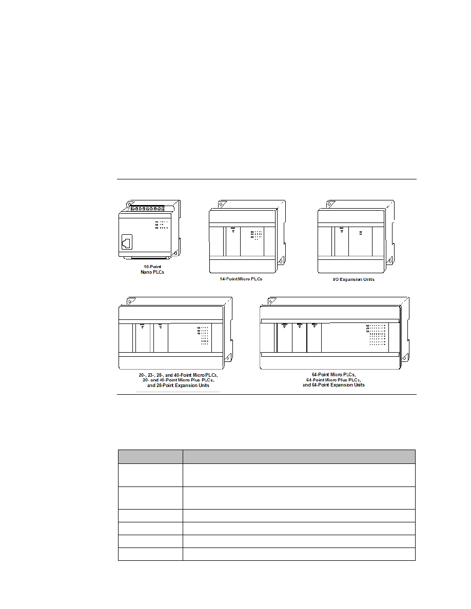
This chapter compares the features of the many VersaMax Nano, Micro and Micro PLUS PLC 
models that are available.  

Micro PLUS 20/40/64 CPUs have enhanced memory compared to earlier versions of these 
CPUs. Firmware versions 4.00 and later cannot be used with the earlier hardware versions. 

Figure 2 


1.1.1


VersaMax Nano PLCs 

VersaMax Nano PLCs have 10 points of discrete I/O. Two models also provide a 0V to 10V 
analog input. 

Model Number 

Description 

IC200NAL110 

10 Point (6) 12Vdc In, (4) 12 Relay Out, (1) Analog Input, 12Vdc Power 
Supply 

IC200NAL211 

10 Point (6) 24Vdc In, (4) 24 Relay Out, (1) Analog Input, 24Vdc Power 
Supply 

IC200NDD010 

10 Point (6) 12Vdc In, (4) 12Vdc Out, 12Vdc Power Supply 

IC200NDD101 

10 Point (6) 24Vdc In, (4) 24Vdc Out, 24Vdc Power Supply 

IC200NDR001 

10 Point (6) 24Vdc In, (4) Relay Out, 24Vdc Power Supply 

IC200NDR010 

10 Point (6) 12Vdc In, (4) Relay Out, 12Vdc Power Supply 


User Manual 

Chapter 1 

GFK-1645M 

Dec 2019 


Introduction 

1.1.2


VersaMax Micro and Micro PLUS PLCs 

VersaMax Micro PLCs are available with 14 to 64 points of I/O. 

Micro PLUS PLCs are available with 20, 40 or 64 points of I/O. 

Model Number 

Description 

IC200UAA003 

14 Point (8) 120Vac In, (6) 120Vac Out, 120/240Vac Power Supply 

IC200UAA007 

28 Point (16) 120Vac In, (12) 120Vac Out, 120/240Vac Power Supply 

IC200UAL004 

23 Point (13) 12Vdc In, (10) Relay Out, (2) Analog In and (1) Analog Out, 
12Vdc Power Supply 

IC200UAL005 

23 Point (13) 24Vdc In, (1) 24Vdc Out, (9) Relay Out, (2) Analog In and (1) 
Analog Out, 24Vdc Power Supply 

IC200UAL006 

23 Point (13) 24Vdc In, (9) Relay Out, (1) 24Vdc Out, (2) Analog In and (1) 
Analog Out, 120/240Vac Power Supply 

IC200UAR014 

14 Point (8) 120Vac In, (2) Relay Out at 10 Amp, (4) Relay Out at 2 Amp, 
120/240Vac Power Supply 

IC200UAR028 

28 Point (16) 120Vac In, (4) Relay Out at 10 Amp, (8) Relay Out at 2 Amp, 
120/240Vac Power Supply 

IC200UDD020 

20 Point (12) 24Vdc In, (4) 24Vdc Out with ESCP, (4) 24Vdc Out, 24Vdc 
Power Supply 

IC200UDD040 

40 Point (24) 24Vdc In, (16) 24Vdc Out (source), 24Vdc Power Supply 

IC200UDD064 

64 Point (40) 24Vdc In, (24) 24Vdc Out with ESCP (source), 24Vdc Power 
Supply  

IC200UDD104 

14 Point (8) 24Vdc In, (6) 24Vdc Out 2 at 1.0 Amp and 4 at 0.5 Amp, 24Vdc 
Power Supply 

IC200UDD110 

28 Point (16) 24Vdc In, (12) 24Vdc Out, 6 at 1.0 Amp and, 6 at 0.5 Amp, 
24Vdc Power Supply 

IC200UDD112 

14 Point (8) 12Vdc In, (6) 12Vdc Out, 12Vdc Power Supply 

IC200UDD120 

28 Point (16) 24Vdc In, (12) 24Vdc Out with ESCP, 24Vdc Power Supply 

IC200UDD164 

64 Point (40) 24Vdc In, (24) 24Vdc Out (sink), 24Vdc Power Supply 

IC200UDD212 

28 Point (16) 12Vdc In, (12) 12Vdc Out, 12Vdc Power Supply 

IC200UDD220 

20 Point, (12) 24Vdc In, (8) 24Vdc Out (sink), 24Vdc Power Supply 

IC200UDD240 

40 Point (24) 24Vdc In, (16) 24Vdc Out (sink), 24Vdc Power Supply 

IC200UDR001 

14 Point (8) 24Vdc In, (6) Relay Out, 120/240Vac Power Supply 

IC200UDR002 

14 Point (8) 24Vdc In, (6) Relay Out, 24Vdc Power Supply 

IC200UDR003 

14 Point (8) 12Vdc In, (6) Relay Out, 12Vdc Power Supply 

IC200UDR005 

28 Point (16) 24Vdc In, (11) Relay Out, (1) 24Vdc Out, 120/240Vac Power 
Supply 

IC200UDR006 

28 Point (16) 12Vdc In, (12) Relay Out, 12Vdc Power Supply 

IC200UDR010 

28 Point (16) 24Vdc In, (11) Relay Out, (1) 24Vdc Out, 24Vdc Power Supply 

IC200UDR020 

20 Point, (12) 24Vdc In, (8) Relay Out, 24Vdc Power Supply 

IC200UDR040 

40 Point (24) 24Vdc In, (16) Relay Out, 24Vdc Power Supply 

IC200UDR064 

64 Point (40) 24Vdc In, (24) Relay Out, 24Vdc Power Supply 

User Manual 

Chapter 1 

GFK-1645M 

Dec 2019 


Introduction 

Model Number 

Description 

IC200UDR120 

20 Point (12) 24Vdc In, (8) Relay Out, 120/240Vac Power Supply 

IC200UDR140 

40 Point (24) 24Vdc In, (16) Relay Out, 120/240Vac Power Supply 

IC200UDR164 

64 Point (40) 24Vdc In, (24) Relay Out, 120/240Vac Power Supply 

IC200UDR228 

28 Point (16) 24Vdc In, (11) Relay Out, (1) 24Vdc Out, 12/24Vdc 
Power Supply 

IC200UDR440 

40 Point (24) 24Vdc In, (16) Relay Out, 12/24Vdc Power Supply  

1.1.3


VersaMax Micro PLC Expansion Units 

VersaMax  Micro  PLC  Expansion  Units  provide  additional  discrete  points  and  analog  I/O 
channels for the PLC system. Up to four VersaMax Micro PLC Expansion Units of any type can 
be connected to a VersaMax Micro PLC.  

Note: 

The 64-point Expansion Units are supported on Micro PLUS PLCs (20/40/64 point PLCs with 
release 4.0 or later firmware). 

Model Number  Description 

IC200UEC008 

8 Point (4) 24Vdc In, (4) 24Vdc Out with ESCP, 24Vdc Power Supply 

IC200UEC108 

8 Point (4) 24Vdc In, (4) 24Vdc Out, 24Vdc Power Supply  

IC200UEC208 

8 Point (4) 24Vdc In, (4) Relay Out, 24Vdc Power Supply 

IC200UEI008 

8 Point (8) 24Vdc In, 24Vdc Power Supply 

IC200UEI016 

16 Point (16) 24Vdc In, 24Vdc Power Supply 

IC200UEO008 

8 Point (8) 24Vdc Out with ESCP, 24Vdc Power Supply 

IC200UEO016 

16 Point (16) 24Vdc Out with ESCP, 24Vdc Power Supply 

IC200UEO108 

8 Point (8) 24Vdc Out, 24Vdc Power Supply 

IC200UEO116 

16 Point (16) 24Vdc Out, 24Vdc Power Supply 

IC200UER008 

8 Point (8) Relay Out, 24Vdc Power Supply 

IC200UER016 

16 Point (16) Relay Out, 24Vdc Power Supply 

IC200UEX009 

14 Point (8) 120Vac In, (2) Relay Out @ 10 Amps (4) Relay Out @ 2 Amps, 
120/240Vac P.S. 

IC200UEX010 

14 Point (8) 120Vac In, (6) 120Vac Out, 120/240Vac Power Supply 

IC200UEX011 

14 Point (8) 24Vdc In, (6) Relay Out, 120/240Vac Power Supply 

IC200UEX012 

14 Point (8) 24Vdc In, (6) Relay Out, 24Vdc Power Supply 

IC200UEX013 

14 Point (8) 12Vdc In, (6) Relay Out, 12Vdc Power Supply 

IC200UEX014 

14 Point (8) 24Vdc In, (6) 24Vdc Out, 24Vdc Power Supply 

IC200UEX015 

14 Point (8) 12Vdc In, (6) 12Vdc Out, 12Vdc Power Supply 

IC200UEX064 

64 point (40) 24Vdc In; (24) Relay Out, 24Vdc Power Supply 

IC200UEX122 

14 Point (8) 24Vdc In, (6) 24Vdc Out with ESCP, 24Vdc Power Supply 

IC200UEX164 

64 point (40) 24Vdc In; (24) Relay Out, 120/240Vac Power Supply 

IC200UEX209 

28 Point (16) 120Vac In, (4) Relay Out at 10 Amp, (8) Relay Out at 2 Amp, 
120/240Vac P.S. 

IC200UEX210 

28 Point (16) 120Vac In, (12) 120Vac Out, 120/240Vac Power Supply 

User Manual 

Chapter 1 

GFK-1645M 

Dec 2019 


Introduction 

Model Number  Description 

IC200UEX211 

28 Point (16) 24Vdc In, (12) Relay Out, 120/240Vac Power Supply 

IC200UEX212 

28 Point (16) 24Vdc In, (12) Relay Out, 24Vdc Power Supply 

IC200UEX213 

28 Point (16) 12Vdc In, (12) Relay Out, 12Vdc Power Supply 

IC200UEX214 

28 Point (16) 24Vdc In, (12) 24Vdc Out, 6 at 1.0 Amp and, 6 at 0.5 Amp, 
24Vdc Power Supply 

IC200UEX215 

28 Point (16) 12Vdc In, (12) 12Vdc Out, 12Vdc Power Supply 

IC200UEX222 

28 Point (16) 24Vdc In, (12) 24Vdc Out with ESCP, 24Vdc Power Supply 

IC200UEX264 

64-point (40) 24Vdc In; (24) 24Vdc Source Out, 24Vdc Power Supply 

IC200UEX364 

64-point (40) 24Vdc In; (24) 24Vdc Sink Out, 24Vdc Power Supply 

IC200UEX616 

6 Point (4) Analog In and (2) Analog Out, 12Vdc Power Supply 

IC200UEX624 

4 Point (4) Analog In, 24Vdc Power Supply 

IC200UEX626 

6 Point (4) Analog In and (2) Analog Out, 24Vdc Power Supply 

IC200UEX636 

6 Point (4) Analog In and (2) Analog Out, 100-240Vac Power Supply 

IC200UEX724 

4 RTD, Pt 100 In, 24Vdc Power Supply 

IC200UEX726 

4 RTD, Pt 100 In and (2) Analog Out, 0 to 20mA, 4 to 20mA or 0 to 10Vdc, 
24Vdc Power Supply 

IC200UEX734 

4 RTD, Pt 100 In, 120/240Vac Power Supply 

IC200UEX736 

4 RTD, Pt 100 In and (2) Analog Out, 0 to 20mA, 4 to 20mA or 0 to 10Vdc, 
120/240Vac Power Supply 

IC200UEX824 

4 Thermocouple Input, 24Vdc Power Supply 

IC200UEX826 

4 Thermocouple In and (2) Analog Out, 0 to 20mA or 0 to10Vdc, 24Vdc 
Power Supply 

IC200UMM002

1


2 Axis Servo Motion Module, 24Vdc Power Supply 

IC200UMM102

1


2 Axis Servo Motion Module, 120/240Vac Power Supply 

1.1.4


Option Modules 

Option Modules can be used to enhance the functionality of a 20, 40, or 64-point (release 
3.6 or later) VersaMax Micro or Micro PLUS PLC. 

Model Number  Description 

IC200USB001 

RS232, Extra Port Option Module with 2 analog inputs 

IC200USB002 

RS485, Extra Port Option Module with 2 analog inputs 

IC200UMB001 

Memory Pack Module 

IC200UUB001 

USB / RS232 Conversion Option Module  

IC200UEM001 

Ethernet Option Module  


1


For Motion Module operating details, refer to the VersaMax Micro PLC MicroMotion Modules Manual, GFK-2471A. 

User Manual 

Chapter 1 

GFK-1645M 

Dec 2019 


Introduction 

1.2


Comparison of Program and Data Memory 
Available 

The  following  table  compares  the  amounts  of  program  and  data  memory  available  with 
VersaMax Nano, Micro and Micro PLUS PLCs. 

Reference Type 

Reference Range 

10-Point 
Nano 
PLCs 

14-Point 
Micro 
PLCs 

23- and 
28-Point 
Micro 
PLCs 

20-, 40-, 
and 64-
Point 
Micro/ 
Micro 
PLUS PLCs 

User program logic 

Not applicable 

2K words   9K words   9K words 

24K words 

Discrete inputs 

%I0001 - %I0512 

512 bits  

512 bits  

512 bits  

512 bits  

Discrete outputs 

%Q0001 - %Q0512 

512 bits  

512 bits  

512 bits  

512 bits  

Discrete global 
references 

%G0001 - %G1280 

1280 bits   1280 bits   1280 bits   1280 bits  

Discrete internal 
coils 

%M0001 - %M1024 

1024 bits   1024 bits   1024 bits   1024 bits  

Discrete temporary 
coils 

%T0001 - %T0256 

256 bits  

256 bits  

256 bits  

256 bits  

System status 
references 

%S0001 - %S0032 

32 bits  

32 bits  

32 bits  

32 bits  


%SA0001 - %SA0032 

32 bits  

32 bits  

32 bits  

32 bits  


%SB0001 - %SB0032 

32 bits  

32 bits  

32 bits  

32 bits  


%SC0001 - %SC0032 

32 bits  

32 bits  

32 bits  

32 bits  

System register 
references 
10-pt, 14-pt PLCs 
23-pt and 28-pt PLCs 
20-pt  and 40-pt PLCs 
64-pt PLCs 

 
%R0001 - %R0256 
%R0001 - %R2048 
%R0001 - %R16384 
%R0001 - %R32640 

 
256 words 

 
256 words 


2K words 


32K words 
32K words 

Analog and High-
Speed Counter 
inputs 

%AI0001 - %AI0128 

128 words   128 words   128 words   128 words  

Analog outputs 

%AQ0001 - %AQ0128  128 words   128 words   128 words   128 words  


User Manual 

Chapter 1 

GFK-1645M 

Dec 2019 


Introduction 

1.3


Comparison of PLC Features 

The table below compares the features of VersaMax Nano PLCs and Micro PLCs. 

Feature 

10-Point 
Nano PLCs 

14-
Point 
Micro 
PLCs 

23-Point 
Micro PLCs 

28-Point 
Micro 
PLCs 

20-, 40-, and 
64-Point 
Micro/ 
Micro PLUS 
PLCs 

Run/Stop Mode Select 
Switch 


Connection for an external 
mode switch 


Potentiometer Inputs (2)  


optional 

Built-in Analog I/O  

1 voltage 
out on some 
models 


2 in (V/C) and 
1 out (V/C) 


Capacitor memory backup 
time, minimum 
(Hardware version C and 
above) 

3 days 

3 days 

30 minutes 

30 minutes  30 minutes 

External high capacity 
battery to back up RAM  


optional 

optional 

optional 

LEDs: PWR, RUN, OK, point 
status 


Removable wiring terminal 
assemblies 


Accepts Up to 4 Expansion 
Units 


Maximum I/O Count with 
Expansion Units 


126 

135 

140 

20-point: 276 
40-point: 296 
64-point: 320 

RS-232 Port 1 with RJ-45 
Connector 


SNP/SNPX Master 


SNP/SNPX Slave  


2-Wire RTU Slave 


4-Wire RTU Slave 


Configurable for Serial I/O 


Modbus RTU Master 


Port 2  


SNP/SNPX Slave  


SNP/SNPX Master  


2-Wire RTU Slave 


User Manual 

Chapter 1 

GFK-1645M 

Dec 2019 


Introduction 

Feature 

10-Point 
Nano PLCs 

14-
Point 
Micro 
PLCs 

23-Point 
Micro PLCs 

28-Point 
Micro 
PLCs 

20-, 40-, and 
64-Point 
Micro/ 
Micro PLUS 
PLCs 

4-Wire RTU Slave 


Modbus RTU Master 


(rel. 2.02 and 
later) 


(rel. 2.02 
and later) 


Configurable for Serial I/O 


RS-232, RS-485/422, USB, 
and Memory Option 
Modules 


VersaMax Serial to Ethernet 
support 


LD and Instruction List 
programming 


Program Functions 
compatible with Series 90-
30 and Series 90 Micro PLCs 


Subroutines 

64 

64 

64 

64 

Floating Point functions 


64-Point Expansion support   


(Rel 4.0 or 
later) 

Ethernet Communications 
module support 


Motion Module support 


Online program changes 


(Rel 4.0 or 
later) 


User Manual 

Chapter 1 

GFK-1645M 

Dec 2019 


Introduction 

1.4


Comparison of I/O and Power Features for PLCs 

Model 
Number 

Discrete 
Points 

Input Power  DC Power for 

inputs and 
field devices 

DC 
Inputs 

AC 
Inputs 

Analog 
Inputs 

Relay 
Outputs 

DC 
Outputs 

AC 
Outputs 

Analog  
Output

Nano PLCs 

NAL110  10 

12Vdc 


NAL211  10 

24Vdc 


NDD010  10 

12Vdc 


NDD101  10 

24Vdc 


NDR001  10 

24Vdc 


NDR010  10 

12Vdc 


Micro and Micro PLUS PLCs 

UAA003  14 

100/240Vac 


UAA007  28 

100/240Vac 


16 


12 


UAL004  23 

12Vdc 


13 


10 


UAL005  23 

24Vdc 


13 


UAL006  23 

100/240Vac 


13 


UAR014  14 

100/240Vac 


6

2


UAR028  28 

100/240Vac 


16 


12

2


UDD020  20 

24Vdc 


12 


4 LCDC, 
4 ESCP 


UDD040  40 

24Vdc 


24 


16 


UDD104  14 

24Vdc 


UDD064  64 

24Vdc 


40 


24, ESCP   


UDD110  28 

24Vdc 


16 


12 


UDD112  14 

12Vdc 


UDD120  28 

24Vdc 


16 


12, ESCP   


UDD164  64 

24Vdc 


40 


24 


UDD220  20 

24Vdc 


12 


UDD212  28 

12Vdc 


16 


12 


UDD240  40 

24Vdc 


24 


16 


UDR001  14 

100/240Vac 


UDR002  14 

24Vdc 


UDR003  14 

12Vdc 


UDR005  28 

100/240Vac 


16 


11 


UDR006  28 

12Vdc 


16 


12 


UDR010  28 

24Vdc 


16 


11 


UDR020  20 

100/240Vac 


12 


2

 Two outputs rated 10 Amps


User Manual 

Chapter 1 

GFK-1645M 

Dec 2019 


Introduction 

10 

Model 
Number 

Discrete 
Points 

Input Power  DC Power for 

inputs and 
field devices 

DC 
Inputs 

AC 
Inputs 

Analog 
Inputs 

Relay 
Outputs 

DC 
Outputs 

AC 
Outputs 

Analog  
Output

UDR040  40 

24Vdc 


24 


16 


UDR064  64 

24Vdc 


40 


24 


UDR120  20 

100/240Vac 


12 


UDR140  40 

100/240Vac 


24 


16 


UDR164  64 

100/240Vac 


40 


24 


UDR228  28 

24Vdc 


16 


11 


UDR440  40 

12Vdc 
24Vdc 


24 


16 


1.5


Comparison of I/O and Power Features for 
Expansion Units 

Model 
Number 

Total 
Points 

Input 
Power 

DC Power 
for inputs 
and field 
devices 

DC 
Inputs 

AC 
Inputs 

Analog 
Inputs 

Relay 
Outputs 

DC  
Outputs 

AC 
Outputs 

Analog  
Output

UEC008 

24Vdc 


4, ESCP   


UEC108 

24Vdc 


UEC208 

24Vdc 


UEI008 

24Vdc 


UEI016 

16 

24Vdc 


16 


UEO008 

24Vdc 


8, ESCP   


UEO108 

24Vdc 


UEO016 

16 

24Vdc 


16, ESCP   


UEO116 

16 

24Vdc 


16 


UER008 

24Vdc 


UER016 

16 

24Vdc 


16 


UEX009 

14 

100/240Vac 


62 


UEX010 

14 

100/240Vac 


UEX011 

14 

100/240Vac 


UEX012 

14 

24Vdc 


UEX013 

14 

12Vdc 


UEX014 

14 

24Vdc 


UEX015 

14 

12Vdc 


UEX064 

64 

24Vdc 


40 


24 


UEX122 

14 

24Vdc 


6, ESCP   


UEX164 

64 

24Vdc 


40 


24 


UEX209 

28 

100/240Vac   


16 


122 


User Manual 

Chapter 1 

GFK-1645M 

Dec 2019 


Introduction 

11 

Model 
Number 

Total 
Points 

Input 
Power 

DC Power 
for inputs 
and field 
devices 

DC 
Inputs 

AC 
Inputs 

Analog 
Inputs 

Relay 
Outputs 

DC  
Outputs 

AC 
Outputs 

Analog  
Output

UEX210 

28 

100/240Vac 


16 


12 


UEX211 

28 

100/240Vac 


16 


12 


UEX212 

28 

24Vdc 


16 


12 


UEX213 

28 

12Vdc 


16 


12 


UEX214 

28 

24Vdc 


16 


12 


UEX215 

28 

12Vdc 


16 


12 


UEX222 

28 

24Vdc 


16 


12, ESCP   


UEX264 

64 

24Vdc 


40 


24 


UEX364 

64 

24Vdc 


40 


24 


UEX616 

12Vdc 


UEX624 

24Vdc 


UEX626 

24Vdc 


UEX636 

100/240Vac   


UEX724 

24Vdc 


4 RTD 


UEX726 

24Vdc 


4 RTD 


UEX734 

100/240Vac   


4 RTD 


UEX736 

100/240Vac   


4 RTD 


UEX824 

24Vdc 


4 TC 


UEX826 

24Vdc 


4 TC 


UMM002 


24Vdc 


UMM102 


100/240Vac   


User Manual 

Chapter 1 

GFK-1645M 

Dec 2019 


Introduction 

12 

1.6


VersaMax Serial to Ethernet Adapter 

The VersaMax

 IC200SET001 Serial to Ethernet Adapter (VMSE) can be used to connect a 

VersaMax Micro, Micro PLUS or Nano PLC to an Ethernet network. 

Figure 3 


1.6.1


Firmware Options 

By default, SRTP/SNP firmware is loaded in flash memory. Use SRTP/SNP to communicate 

with  VersaPro™,  CIMPLICITY™  HMI,  Series  90

-30

,  Series  90-70

,  and  other  Emerson 

products. 

Additional firmware options are provided on the CD that is shipped with the VMSE. These 
include  Modbus  TCP/RTU,  and  Pass  Thru  firmware,  which  can  be  used  to  send  serial 
communication via Ethernet.  

1.6.2


Serial Interface  

The RJ-45 port on the VMSE supports RS-232. The screw block port supports both RS-232 
and  RS  485/422.  Setting  the  switch  on  the  front  of  the  VMSE  and  configuring  the  VMSE 
setup selects RS 232 or RS-485/422. Only one port can be used at a time.  

1.6.3


Network Interface  

The VMSE supports 10/100 Mbit Ethernet through its RJ-45 (10BaseT) connector. 

1.6.4


Power Requirements 

The required input voltage can vary between 9Vdc and 30Vdc (or 24Vac) with a maximum 
of 3 Watts. The VMSE can be powered from the 12- or 24-Volt supply on a VersaMax Micro 
or Micro PLUS PLC (200mA available), or an external supply can be used. For a Nano PLC, an 
external power supply is required.


User Manual 

Chapter 1 

GFK-1645M 

Dec 2019 


Introduction 

13 

1.7


Logic-Driven Read/Write Flash Memory 
Feature 

Release 3.0 and later Micro and Micro PLUS PLCs support two Service Requests that can be 
used in the application program to read data from and write data to flash memory. 

The Logic-Driven Read/Write Flash feature can: 


Write selected data to flash using Service Request (SVCREQ) logic in the application 
program 


Write  /  read  one  to  ten  consecutive  Reference  Variables  of  same  type  with  one 
Service Request 


Up to 10 words of %R, %AI, %AQ 


Up to 10 bytes of %I, %Q, %M, %T, %G 


Up to 8k bytes of reference memory can be stored in flash. If a request is made to 
store more than 8k bytes in flash, a fault is logged in the PLC Fault Table. 

See Chapter 24: for details and logic examples. 

1.8


Online Program Changes 

In release 4.0 or later Micro PLUS PLCs, you can perform online program changes to edit 
and download logic to the PLC without putting the PLC into Stop mode. Online program 
changes consist of: 


Word-for-word change 


Run mode store (RMS) 

1.8.1


Word for Word Changes 

Changes to the program that do not modify the size of the program are considered word-
for-word  changes.  Examples  include  changing  the  type  of  contact  or  coil  or  changing  a 
reference  address  used  for  an  existing  function  block.  Changing  an  operand  is  usually  a 
word-for-word change. A word-for-word change can be made and downloaded to the PLC 
while online in programmer mode without having to download the entire block of logic. 

1.8.2


Run Mode Store 

Run Mode Store consists of downloading logic to a PLC while it is in Run mode. Changes in 
logic can account for the same or a different amount of memory as the original logic. 

The Run Mode Store operation requires the modified logic block(s) size to be  within the 
available free memory. 

Example: In order to modify or add a logic block of 10 Kbytes and perform a Run Mode Store, 
at least 10 Kbytes of free memory should be available. A Run Mode Store with the maximum 
user logic (48K) is possible only when there is no user logic present in the PLC. 

User Manual 

Chapter 1 

GFK-1645M 

Dec 2019 


Introduction 

14 

Note: 

Online  program  changes  should  not  be  performed  on  active  motion  function  blocks.  Motion 
functionality is not guaranteed if user performs word for word change or Run Mode Store on active 
motion function blocks. 

1.9


Documentation 

VersaMax Manuals 

VersaMax PLC User's Manual 


GFK-1503 

VersaMax Modules, Power Supplies, and Carriers User's Manual   

GFK-1504 

VersaMax System DeviceNet Communications Modules User's Manual 

GFK-1533 

VersaMax System Profibus Slave Modules User's Manual   


GFK-1534 

VersaMax System Genius Network Interface Unit User's Manual   

GFK-1535 

VersaMax I/O and Industrial Networking Application Guide 


GFK-1563 

VersaMax Micro PLCs and Nano PLCs User's Manual 


GFK-1645 

VersaPro Programming Software User's Guide   


GFK-1670 

VersaMax System AS-i Network Master Module User's Manual 


GFK-1697 

VersaMax Serial to Ethernet Adapter User's Manual 


GFK-1852 

VersaMax System Ethernet Network Interface Unit User Manual   

GFK-1860 

VersaMax PLC Station Manager User's Manual   


GFK-1876 

VersaMax IP Installation Manual 


GFK-2307 

VersaMax MicroMotion Modules IC200UMM002/102 


GFK-2471 

VersaMax PROFINET Scanner (PNS) Manual 


GFK-2721 

VersaMax PROFIBUS Master Module, IC200BEM003 


GFK-2740 

VersaMax Controllers Secure Deployment Guide  


GFK-2955 

In  addition  to  these  manuals,  datasheets  and  product  update  documents  describe 
individual modules and product revisions. The most recent PACSystems documentation is 
available  on  the  Emerson  support  website

https://www.emerson.com/Industrial-

Automation-Controls/support

. 

1.10


Revisions in this Manual 

Rev 

Date 

Description 

Dec 2019 

Following 

Emerson’s  acquisition  of  this  product, 

changes  have  been  made  to  apply  appropriate 
branding and registration of the product with required 
certification agencies. No changes to material, process, 
form, fit or functionality.


Sep 2015 

Correction to figure in section 9.7.4 


User Manual 

Chapter 2 

GFK-1645M 

Dec 2019 


VersaMax Nano PLCs 

15 

Chapter 2:


VersaMax Nano PLCs 

This chapter describes the features and specifications of VersaMax Nano PLCs. 

IC200NAL110 

Nano PLC with 10 Discrete-Points and 1 Analog Input:  

11-Point (6) 12Vdc In, (4) Relay Out, 1 Analog input,  

12Vdc Power Supply 

IC200NAL211  

Nano PLC with 10 Discrete-Points and 1 Analog Input:  

(6) 24Vdc In, (4) Relay Out, 1 Analog input,  

24Vdc Power Supply 

IC200NDD010 

10-Point Nano PLC: (6) 12Vdc In, (4) 12Vdc Out,  

12Vdc Power Supply  

IC200NDD101 

10-Point Nano PLC: (6) 24Vdc In, (4) 24Vdc Out,  

24Vdc Power Supply  

IC200NDR001 

10-Point Nano PLC: (6) 24Vdc In, (4) Relay Out,  

24Vdc Power Supply  

IC200NDR010 

10-Point Nano PLC: (6) 12Vdc In, (4) Relay Out,  

12Vdc Power Supply 

2.1


VersaMax Nano PLC Features 

VersaMax Nano PLCs offer the perfect solution for smaller packaging machines, dispensing 
machines, and relay replacement applications with up to 6 inputs and 4 outputs. In spite of 
their small size, these versatile controllers provide powerful programming features such as 
built-in  high-speed  counter  functionality,  support  for  floating-point  function  blocks  and 
subroutines, ability to assign passwords and privilege levels, and override capability. 

Figure 4 


User Manual 

Chapter 2 

GFK-1645M 

Dec 2019 


VersaMax Nano PLCs 

16 

All VersaMax Nano PLCs feature: 


Two non-

removable recessed “box

-st

yle” terminal strips.


An  external  Run/Stop  switch  can  be  wired  to  the  Nano  PLC.  The  switch  can  be 
configured as a run/stop switch, or a memory protect switch, and used for clearing 
faults when a fatal fault exists. 


Configurable to read configuration at power-up from either RAM or flash memory 
(ROM). Can also be configured to read application program from flash at power-up.   


Capacitor backs up RAM for at least 30 minutes on hardware revisions C or above. 


Full-featured programming Instruction Set with floating point math. 


2K words of program memory, 256 words of registers. 

2.1.1


Nano PLC General Specifications 

Typical Scan Rate 

1.3 ms/K for Boolean logic (see Appendix A:) 

Output Power Supplies 

+5Vdc on pin 7 of Serial Port, 100mA max  

Maximum number of slave devices per RS-485 
network 

8 (can be increased with a repeater). Requires 
IC200ACC415. 

Real-time clock accuracy (for timer functions) 

±0.5% 

2.1.2


RS-232 Serial Port 

The RS-232 serial port has an RJ-45 connector. The serial port defaults to SNP protocol, and 
can be configured for SNP/SNPX, slave or RTU slave using the configuration software. It can 
also  be  configured  for  Serial  I/O  and  controlled  using  COMMREQs  from  the  application 
program.  The  port  automatically  switches  from  RTU  to  SNP  for  programmer 
communications. 

2.1.3


Status LEDs 

LEDs provide quick visual verification of operating status. In addition to LEDs for Power, OK, 
and Run mode, there is an LED for each I/O point. 

Figure 5 


User Manual 

Chapter 2 

GFK-1645M 

Dec 2019 


VersaMax Nano PLCs 

17 

2.1.4


High-Speed Counters  

A VersaMax Nano PLC can be configured to provide built-in high-speed counter and pulse 
operation. 

When configured for High-Speed Counter operation, inputs can be set up as: 


Up to three Type A Counters or 


1 Type A and 1 Type B Counter. 

Each counter provides direct processing of rapid pulse signals up to 10 kHz for industrial 
control  applications  such  as  meter  proving,  turbine  flowmeter,  velocity  measurement, 
material handling, motion control, and process control. 

Each counter can be enabled independently. Type A counters can be configured for up or 
down  counting  (default  is  up)  and  for  positive  or  negative  edge  detection  (default  is 
positive). The type B counter provides an A Quad B counting function. 

Nano PLCs with DC outputs provide up to 3 High-Speed Counter outputs, and/or Pulse Train 
or Pulse-Width Modulated outputs. 

Nano PLCs with relay outputs also provide up to 3 High-Speed Counter outputs. However, 
relay outputs cannot be used as Pulse Train or Pulse-Width Modulated outputs. 

2.2


IC200NAL110 Nano PLCs with 10 Discrete 
Points and 1 Analog Input: (6) 12Vdc In, (4) 
Relay Out, 1 Analog Input, 12Vdc Power 
Supply  

VersaMax Nano PLC IC200NAL110 has six DC inputs, one analog input, and four  normally 
open  2-Amp  relay  outputs  that  can  control  5Vdc  to  30Vdc  or  5Vac  to  250Vac  output 
devices. It uses +12Vdc nominal input power for PLC operation. 

2.2.1


DC Inputs 

The module’

s six configurable DC inputs can be used as positive or negative logic standard 

inputs  or  High-Speed  Counter  inputs.  When  used  as  standard  inputs,  the  input 
characteristics are compatible with a wide range of input devices, such as pushbuttons, limit 
switches, and electronic proximity switches. 

2.2.2


Analog Input 

Input IN1 can be used as an analog input (8-bit resolution), for analog signals in the 0V to 
10V range. The analog input cannot be software calibrated. 


Content      ..     1      2      3      4      ..