TSX Micro PLCs TSX 3705/3708/3710/3720. Implementation Manual (Volume 1) - page 9
Terminal port
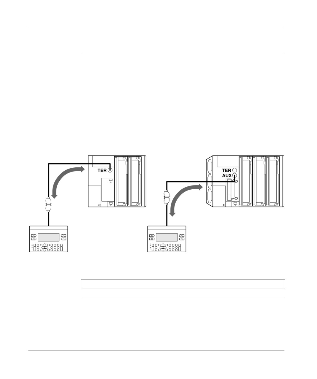
Operator dialog console
General
The operator dialog console uses the UNI-TE protocol to communicate with the
offline PLC and with the other stations in the network architecture.
If a type TSX 37 PLC is used, the operator dialog console is auto-supplied. It must
therefore be connected onto the AUX port to leave the TER port available for a
terminal which might need a supply (FTX 117, for example).
The connection cable reference between the terminal port and an operator dialog
console CCX 17 is given below.
Example of a connection :
TSX 37-10
TSX 37-2•
XBT-Z 968
XBT-Z 968
T CCX CB10 002
T CCX CB10 002
CCX 17
CCX 17
Note: The T CCX CB10 002 is supplied with the CCX 17.
TSX DM 37 xxE
323
Terminal port
Programming and adjustment terminal and operator dialog console
General
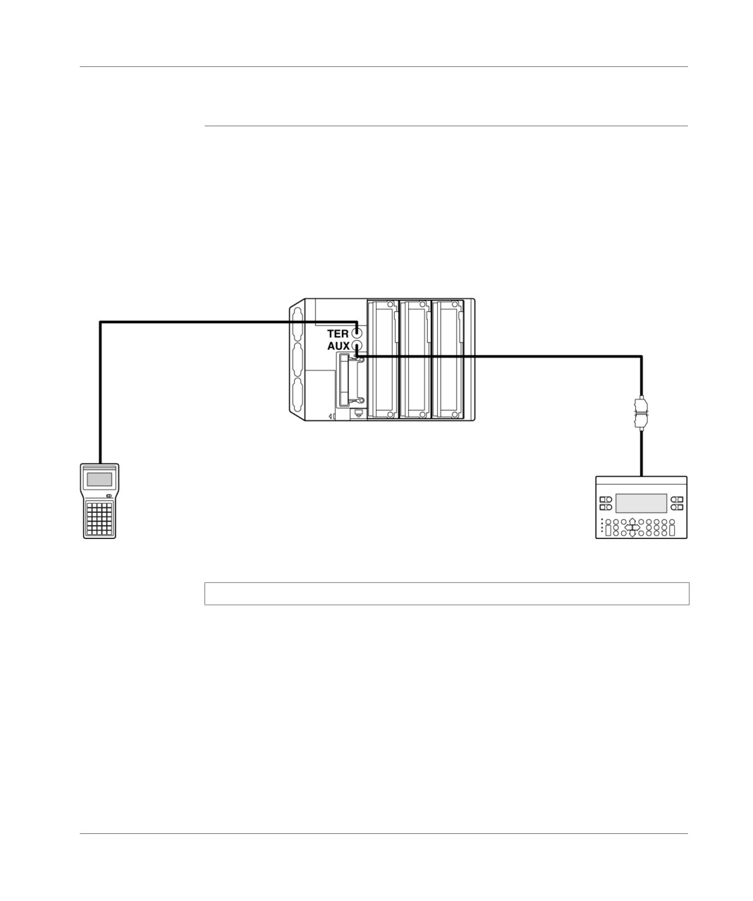
The terminal port of a PLC can manage two devices as multidrops . the
programming and adjustment program, and an operator dialog console.
The PLC’s TSX 37-21 and TSX 37-22 have two terminal ports. Each of these two
ports can therefore receive one of these devices. Because the adjustment terminal
FTX 117 is not self-supplied, it must be connected onto the TER port.
Example of a connection :
T FTX 1020/050
XBT-Z 968
T CCX CB10 002
TSX 37-2•
Adjust FTX 117
CCX 17
Note: The cable TSX PCX 1031 does not work on the AUX port of the TSX 37.
324
TSX DM 37 xxE
Terminal port
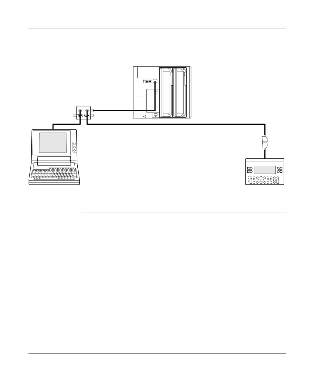
The PLC’s TSX 37-10 have a single terminal port.The simultaneous connection of a
programming terminal and an operator dialog console requires a junction box
TSX P ACC 01 to be used (see next chapter).
TSX 37-10
TSX P ACC 01
TSX PCX 1031
XBT-Z 968
T CCX CB10 002
FT 2100
CCX 17
Irrespective of PLC-type, each connected terminal can be unplugged without
disturbing the operation of the second.
TSX DM 37 xxE
325
Terminal port
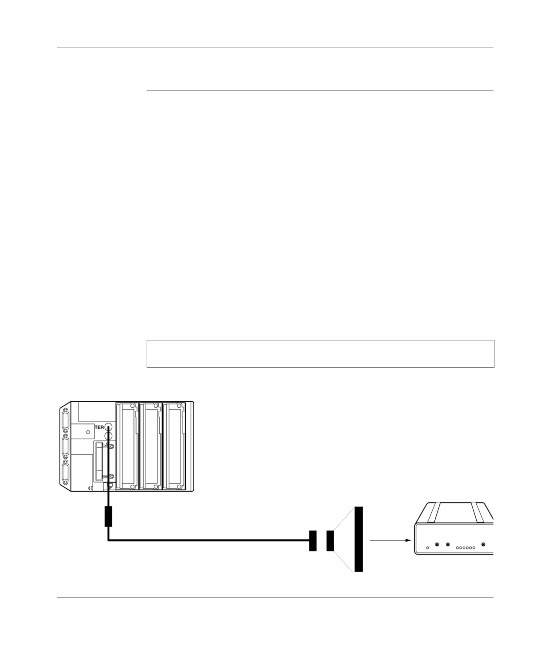
Modem on terminal port
General
The terminal port of the TSX Micro PLC’s of version ≥ 1.5 is compatible with a
connection modem in the protocols UNI-TELWAY master, UNI-TELWAY slave and
character string.
It is imperative that the modem to be connected has the following features
1 supports the 10 or 11 bit by character format if the terminal port is used in UNI-
TELWAY mode (1 Start, 8 pieces of Data, 1Stop, Odd parity or without parity),
2 operate without data compression if the terminal port is used in UNI-TELWAY,
3 can be configured "forced DTR signal" from the side of its RS232 serial port
(when the modem is used in response mode), because this signal is not
connected by the cable,
4 operate without flux control (neither hardware -RTS/CTS-, nor software -XON/
XOFF-) from the side of its RS 232 serial port, as the cable to be used on the
terminal port side can only carry TX, RX and GND signals,
5 operate without carrier control. Warning: this operation mode also uses RTS
and CTS control signals,
6 accept an incoming telephone call while characters reach its RS 322 serial port
(if a modem/telephone network is used in response mode on a terminal port
configured in UNI-TELWAY master).
Note: It is highly recommended that you check with the modem supplier that the
above features are definitely offered by the modem considered.
Connection diagram :
TSX 37
Modem
TSX CTC 09
Adapter if
necessary
TSX PCX 1130
326
TSX DM 37 xxE
Terminal port
Example 1 : for a terminal port in UNI-TELWAY mode, connected to a modem/
telephone network in response mode, the port must have the above characteristics
1 to 6.
Example 2 : for a terminal port in character string mode connected to a modem via
an application-specific line, the port must have the above characteristics from 3 to 5.
Configuration of
The waiting delay must be between 100 and 250 ms.
the terminal port
In master mode, the number of slaves configured must correspond to the real
in UNI-TELWAY
number of slaves present on the bus.
mode
In slave mode, the number of addresses must correspond to those used.
The TSX Micro PLC’s terminal port is configured from the PL7 Micro or PL7 Junior
software.
For further details, please refer to the communication manual TLX DS COM PL7.
TSX DM 37 xxE
327
Terminal port
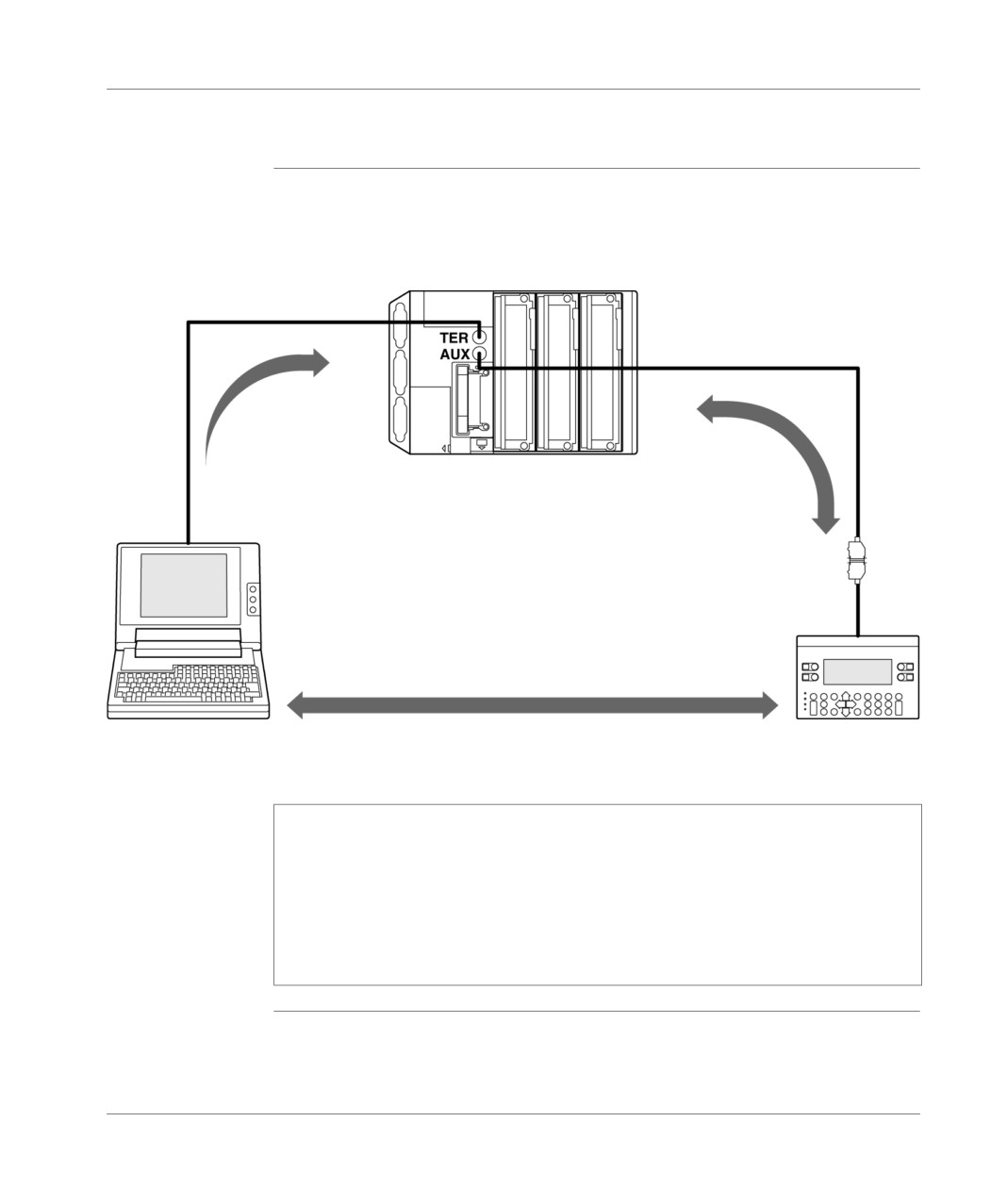
UNI-TELWAY Master
General points
This is the terminal port default operating mode. First and foremost, it enables a
programming terminal and an operator dialog console to be connected.
Example of a connection :
TSX PCX 1031
XBT-Z 968
Client
Client/Server
TSX 37-2•
Slave
T CCX CB10 002
(provided with the CCX 17)
Slave
Client/Server
FT 2100
CCX 17
Note: The master can scan up to eight link addresses: Link addresses 1,2,
and 3 are reserved for the programming terminal, the five other addresses
are available for connecting the following types of devices: operator dialog,
slave PLC, sensors/actuators, or any other slave device which supports the
UNI-TE protocol. If a CCX 17 is used, addresses 4 and 5 are reserved for it.
This mode becomes operational immediately, in fact, within the default
configuration limits. No implementation phase is required for connecting a
device onto this type of link.
328
TSX DM 37 xxE
Terminal port
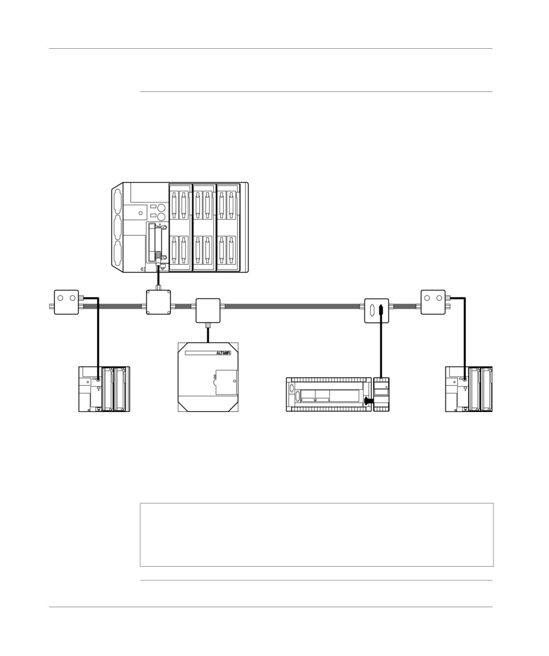
UNI-TELWAY Slave
General points
The UNI-TE protocol for the terminal port enables a TSX 37 PLC to be integrated
into a UNI-TELWAY bus.
Example of a connection :
TSX 37-2•
Master
PCMCIA
communication
card
TSX SCP 114
S1=ON
S1=ON
S2=ON
S2=ON
UNI-TELWAY bus
TSX P
TSX
TSX
TSX
TSX P
ACC 01
SCA 50
SCA 50
SCA 62
ACC 01
TSX CSC 015
TSX 37-10
ATV 16
TSX 17-20
TSX 37-10
Slave
Slave
Slave
Slave
A slave PLC manages up to three consecutive link addresses .
Ad0 (system address),
Ad1 (client application address),
Ad2 (listening application address)
Note: For the connection with a TSX 37 to be possible it is imperative that a
TSX P ACC 01 connection device be used. The different connecting possibilities of
this device are given in the following chapter. For implementing the TSX SCA 50
and TSX SCA 62 devices, consult the TSX DG UTW manual: UNI-TELWAY
Communication Bus (User guide)
TSX DM 37 xxE
329
Terminal port
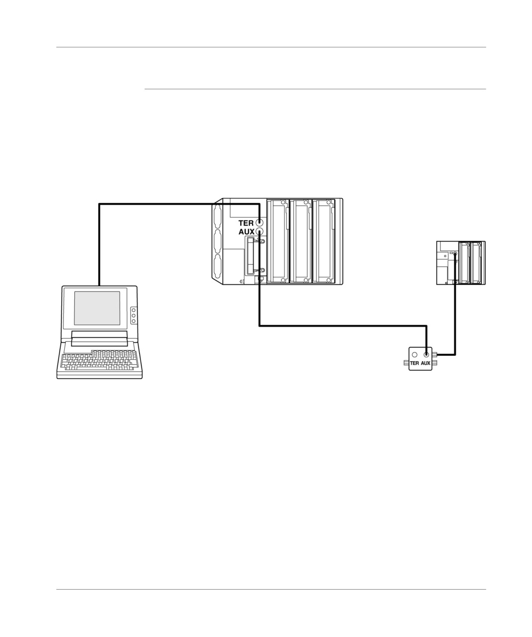
UNI-TELWAY intersection PLC’s
General points
The terminal port authorizes the connection of two PLC’s, one master and the other
slave.
Two possibilities make it possible to obtain this architecture :
Using the terminal port of both PLCs. For this connection to be possible it is
imperative to use a TSX P ACC 01 connection device. The different connecting
possibilities of this device are given in the next chapter.
TSX 37-2•
TSX PCX 1031
Maître
TSX 37-10
Esclave
T FTX CB1 020/050 (distance max. 10 m)
FT 2100
Esclave
S1=ON
S2=ON
TSX P ACC 01
330
TSX DM 37 xxE
Terminal port
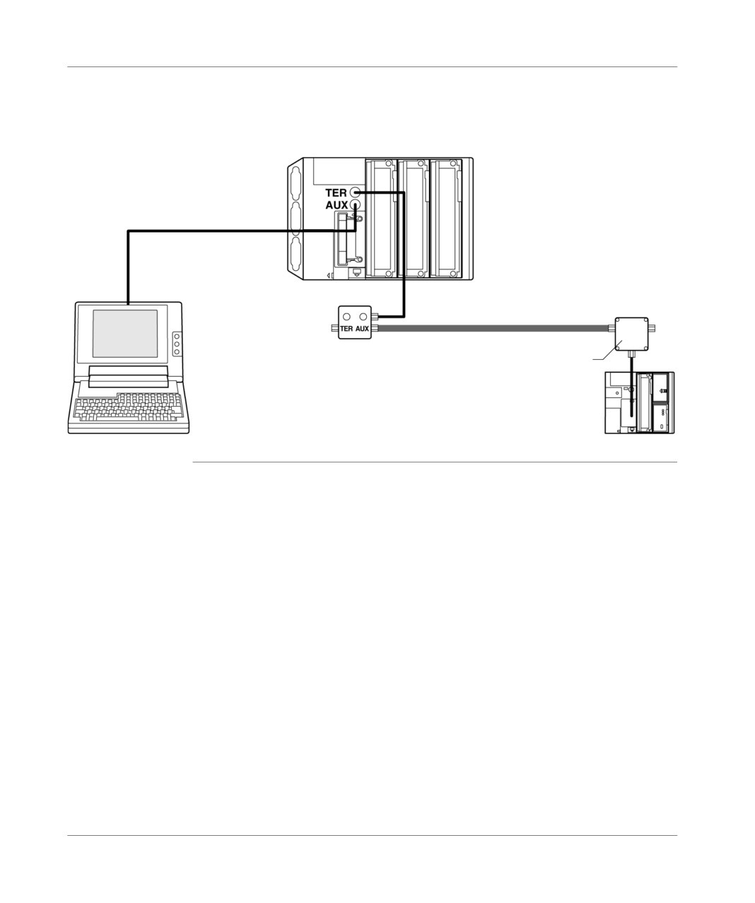
Using a UNI-TELWAY module implanted in one of the available slots in the
second PLC. This module must be configured in UNI-TELWAY slave, for
example, if the terminal port is master.
TSX 37-2•
Maître
T FTX CBF 020
Bus UNI-TELWAY
FT 2100
TSX P ACC 01
TSX SCA 50
Esclave
TSX 37-10
Esclave
TSX DM 37 xxE
331
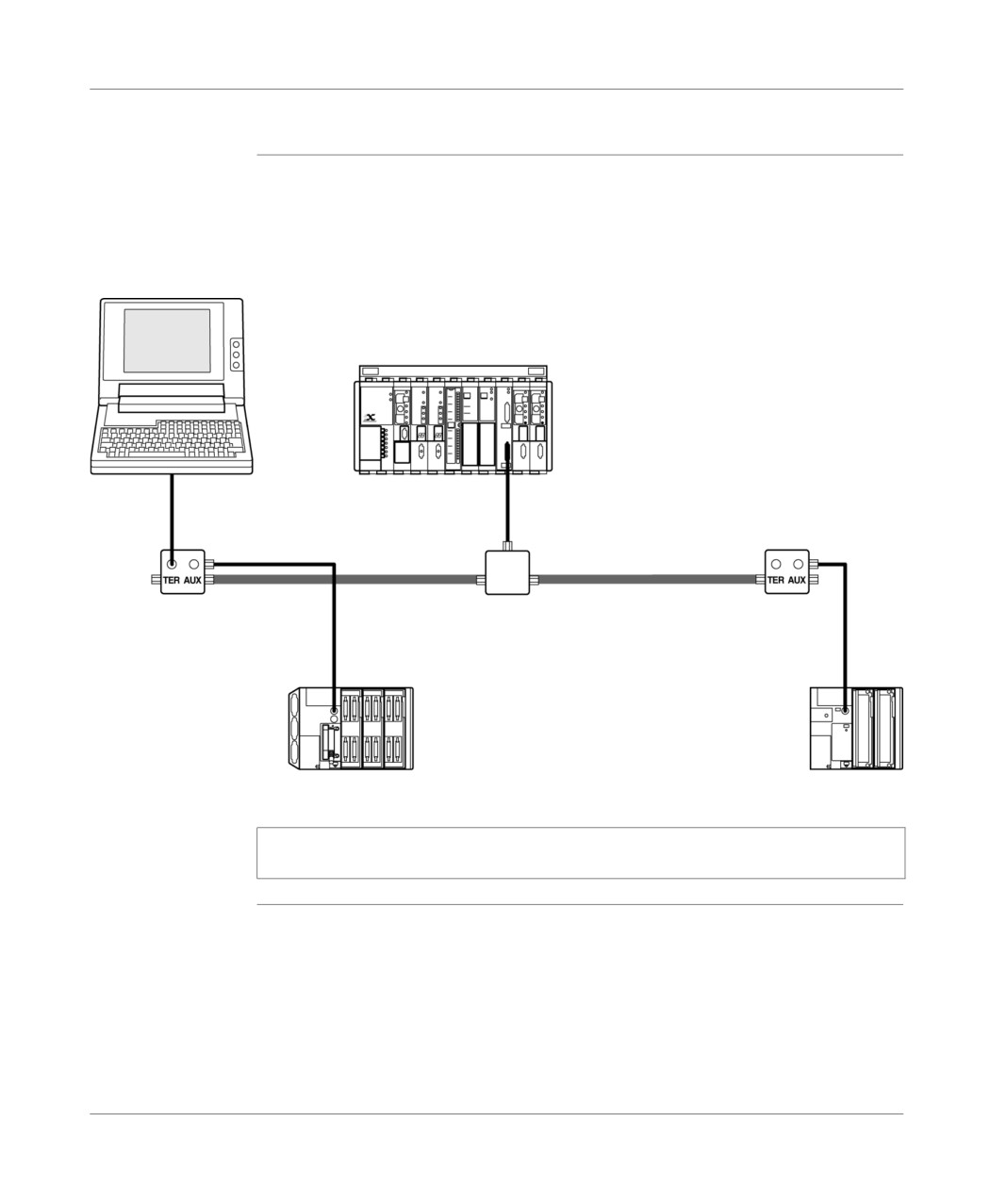
Terminal port
UNI-TELWAY intersection devices
General
The terminal port of the PLC’s TSX 37, authorizes their connection onto a UNI-
TELWAY bus in order to communicate with the following types of devices: variable
speed controllers, sensors/actuators, or with other PLC’s.
When connecting a PLC TSX 37 (master or slave) onto a UNI-TELWAY bus, it is
imperative that you use the device TSX P ACC 01. For further details, refer to the
next chapter.
Example of a connection :
TSX 37-2•
Master
FTX 117
Slave
S1=ON
S2=ON
UNI-TELWAY bus
TSX P ACC 01
TSX SCA 50
TSX SCA 62
ATV 16
Slave
CCX 17
Slave
The connected devices communicate with the PLC, using the UNI-TE protocol.
Communication between different devices is authorized.
The programming terminal can access all these devices directly to carry out tuning
and troubleshooting functions.
Note: For implementing the TSX SCA 50 and TSX SCA 62 devices, consult the
manual TSX DG UTW : UNI-TELWAY Communication Bus (User guide)
332
TSX DM 37 xxE
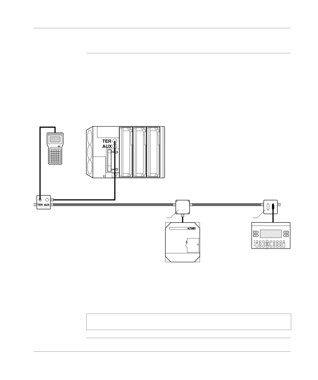
Terminal port
Master PLC, model 40, type TSX
General
A model 40, type TSX PLC can also be configured in bus master UNI-TELWAY and
can control the slaves of the TSX 37 PLC’s.
Example of a connection :
TSX 47-107
Master
FT 2100
Slave
TSX P
S1=ON
S1=ON
CU 1030
S0=ON
S0=ON
UNI-TELWAY bus
TSX P ACC 01
TSX SCA 50
TSX P ACC 01
TSX 37-••
TSX 37-10
Slave
Slave
Note: For implementing the devices: TSX SCA 50 and TSX SCA 62, consult the
manual TSX DG UTW : UNI-TELWAY Communication Bus (User guide)
TSX DM 37 xxE
333
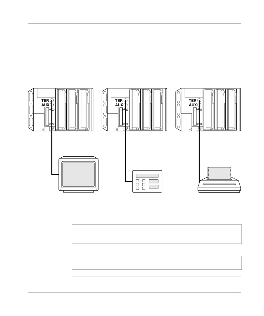
Terminal port
Character string
General points
The terminal port, configured in character mode, allows the connection of one device
from the following types: printer, display screen or application-specific console (table
regulator, for example).
Example of a connection :
TSX 37
TSX 37
TSX 37
Converter cable
Converter cable
Converter cable
RS 485/RS 232
RS 485/RS 232
RS 485/RS 232
TSX PCX 1031
TSX PCX 1031
TSX PCX 1031
Test screen
Loop
Printer
not generating
Controller
the RTS signal
Note: The converter integrated into the TSX PCX 1031 cable is supplied by the
TER port of the PLC; it is therefore impossible to use the AUX port of TSX 37-2
PLCs to connect the cable.
Note: To avoid signal conflicts, no devices should be attached to the PLC's AUX
port.
334
TSX DM 37 xxE
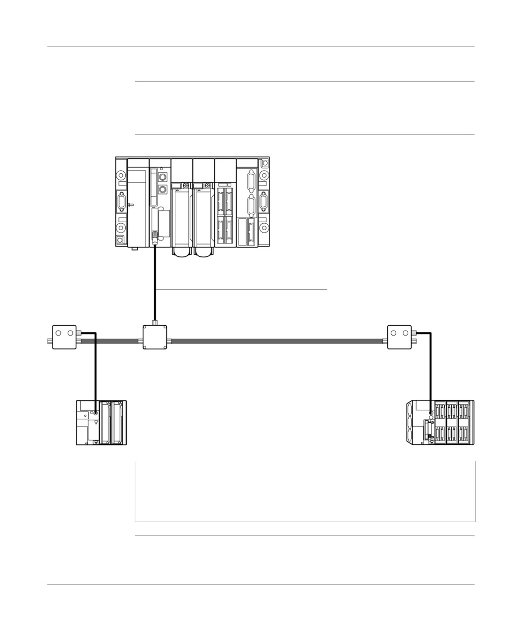
Terminal port
Modbus/JBus
General
The Modbus protocol (Modbus RTU only ) of the terminal port makes it possible to
incorporate a TSX 37 PLC onto a Modbus bus as a slave or master (TSX 37-10/21/
22).
Modbus Slave
Illustration
TSX 57
Master
PCMCIA
communication
card
TSX SCP 114
Master
TSX SCPCM 4030
S1=ON
S1=ON
S2=ON
S2=ON
Modbus/JBus
TSX P
TSX SCA 50
TSX P
ACC 01
ACC 01
TSX 37-10
TSX 37-2•
Slave
Slave
Note: To make the connection of a TSX 37 possible, it is imperative that you use
a TSX P ACC 01. The different possibilities for connecting this device are given in
the next chapter. For implementing the TSX SCA 50 and TSX SCA 62 devices,
consult the TSX DG UTW manual: UNI-TELWAY Communication Bus (User
guide)
TSX DM 37 xxE
335
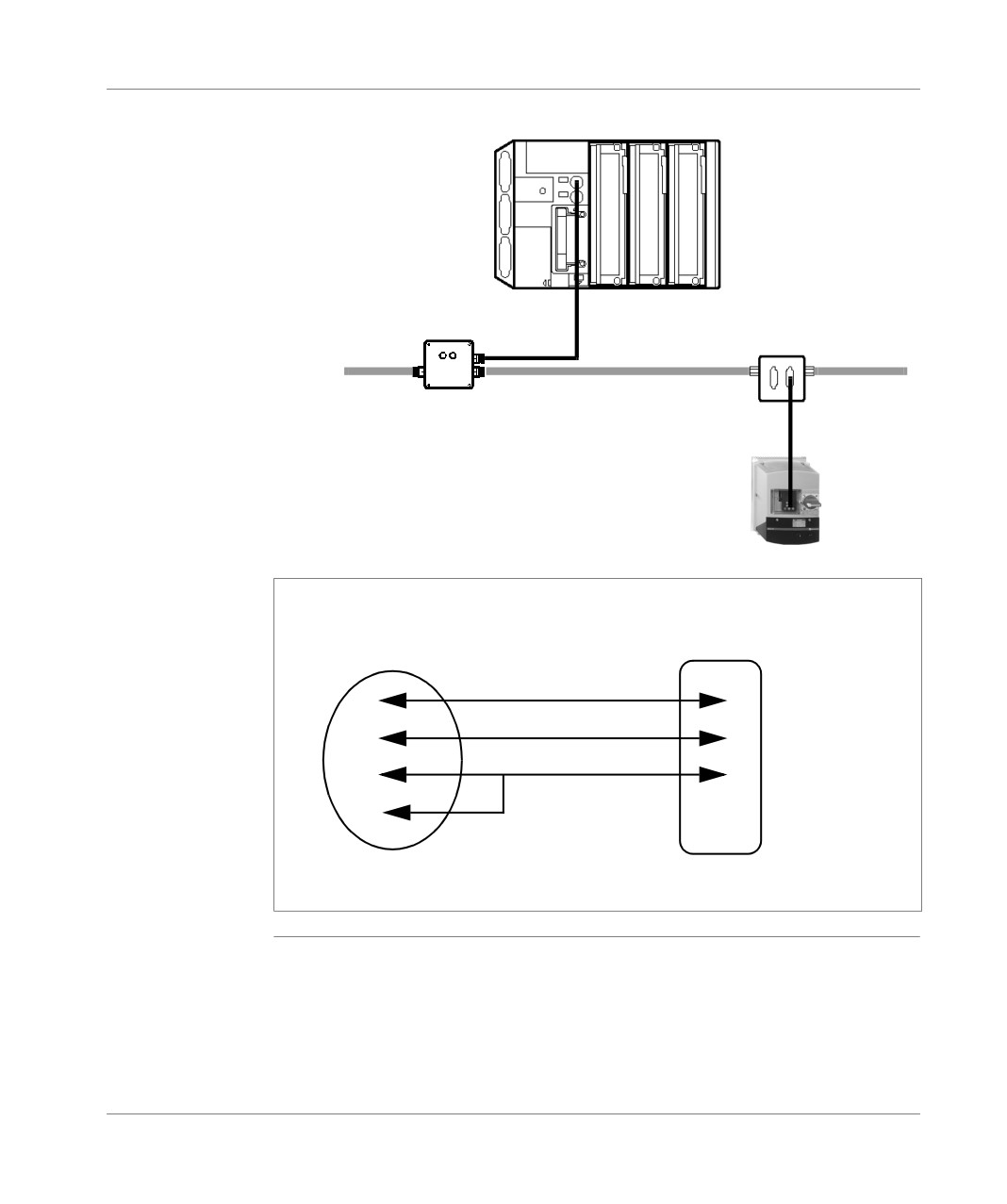
Terminal port
Modbus Master
Sample connections
TSX 37-10/21/22
Master
S1=ON
S2=ON
Modbus
TSX SCA 62
TSX P
ACC 01
vW3A58306
Altivar 58
Slave
Note: If connecting a single ATV 58 to the terminal port of a Micro Modbus master,
you can use the following wiring.
Illustration
D(A)
2
3
D(B)
1
7
0V
7
4
5
INL/DTP
8 pin Mini-Din port
SUB D 9 pins
(Micro terminal port side)
(ATV 58 side)
336
TSX DM 37 xxE

Terminal port
Summary table
General points
The table below enables us to define the cord which links the ports of the TSX 37 to
the peripheral devices.
Connection cordt
PLC port
Examples of connected devices
TER
AUX
TFTX CB 1020 or
X
FTX 117
TFTX CB 1050
X
TSX P ACC 01
TFTX CBF 020
X
X
FTX 507, FTX 417
TSX PCX 1031
X
Programming and setting terminals, printer
terminals, etc.
TSX PCX 1130
X
Devices which do not manage the DTE type RTS
signal<-> DTE : modem
XBT-Z968
X
X
CCX 17, XBT
TSX P ACC 01
X
Connecting to a UNI-TELWAY or a Modbus/JBus
The two cables TSX PCX 1031 and TSX PCX 1130 ensure the conversion of the
RS 485 and RS 232 signals. They allow the connection of the terminal port to the
RS 232 devices which do not manage the RTS.
TSX DM 37 xxE
337

Terminal port
TSX PCX
1031
This multi-function cable enables the PLC to communicate with different devices of
cable
the RS232 series.
The different functions of the series mode are defined according to the position of
the coil turret accessible via the converter unit.
The table below introduces the different functions.
Position of
Function
Status of
Managemen
coil turret
signal/DPT
t of RTS
signal
0
TER MULTI - Connection in point to point
1
Yes
or multi-point mode. UNI-telway master
PLC communication (replace the cable
reference TSX PCU 1030 (1)
1
OTHER MULTI - Connection in multi-point
0
Yes
mode. Other types of connection (replace
the cable reference TSX PCD 1030).
2
TER DIRECT - Connection in point to point
1
No
mode. Uni-telway master PLC
communication defined by the PLC
configuration (replaces the cable
references TSX PCX 1030 (2) and TSX
PCU 1030
3
OTHER DIRECT - Connection in point to
0
No
point mode. Other types of communication
defined by the PLC configuration (replaces
the cable reference TSX PCX 1030 (3)).
Legend
(1)
Replaces also the cable reference TSX PCU 1031
in multi-point mode.
In this case you must update the Uni-telway driver. Depending on your
operating system, the version to use is:
Windows 2000/98/ME/XP ≥ V1.0 IE01
Windows NT4 ≥ V1.4 IE9
Windows 95 ≥ V7.8 IE18
(2)
Switch in master position
(3)
Switch in slave position
338
TSX DM 37 xxE
Terminal port
TSX PCX 1030
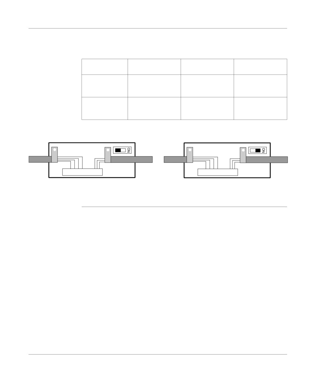
This cable is fitted with a switch which makes it possible to set the PLC in master or
cable
slave mode. The switch can be accessed internally, by removing the metal cover
which contains the electronics. Switch management is as follows :
UNI-TELWAY Master
UNI-TELWAY Slave
Character mode PL7
PL7 configuration
PL7 configuration
configuration
Switch in Master
UNI-TELWAY Master
UNI-TELWAY Master
UNI-TELWAY Master
position
with PL7 configuration
with default
with default
configuration
configuration
Switch in Slave
UNI-TELWAY Slave
UNI-TELWAY Slave
Character mode with
position
with default
with PL7 configuration
PL7 configuration
configuration
Switch adjustment :
M master mode
E slave mode
TSX DM 37 xxE
339
Terminal port
31.3
Attachments
Introduction to this Section
Aim of this
This Section describes the features of the terminal port.
Section
What's in this
This Section contains the following Maps:
Section?
Topic
Page
Properties of the terminal port
341
Connectors on the TSX 37 PLC
343
340
TSX DM 37 xxE

Terminal port
Properties of the terminal port
General
The properties of the terminal port are given in the table below:
Master or slave UNI-
Modbus/JBus mode
Character mode
TELWAY mode
(RTU)
Structure
Physical
Non-isolated RS 485.
Non-isolated RS 485.
Non-isolated RS 485.
interface
Transmission
Protocol
Master/slave multidrop.
Master/slave multidrop.
Without predefined
protocol (application)
Binary flow and
9600 default bit/s can be
9600 default bit/s can be
9600 default bit/s can be
character format
changed from 1200 to
changed from 1200 to
changed from 1200 to
9600 bit/s (1 start bit, 8
19200 bit/s.
9600 bit/s (1 start bit, 7
data bits, 1 parity bit
or 8 data bits, 1 parity bit
(even, odd, or none) and
(even, odd, or none, with
1 stop bit).
or without echo) and 1
stop bit).
Configuration
Number of
Eight maximum (eight
Addresses 1 to 98
A point-to-point device).
devices
addresses managed by
(managed by the
the master).
master).
In slave mode,
addresses 4, 5, 6 are
chosen by default.
In master mode, the
reserved addresses are:
1, 2, 3, for the
programming terminal,
4, 5 if CCX 17 is present,
the others are available.
Length
10 m maximum
10 m maximum
10 m maximum
TSX DM 37 xxE
341

Terminal port
Master or slave UNI-
Modbus/JBus mode
Character mode
TELWAY mode
(RTU)
Utilities
Messaging
Request point-to-point
Modbus standard
Character string with
UNI-TE with the report of
requests
120 bytes max.
a maximum of 128 bytes
The message-end
following the initiative of
character can be
all connected devices.
configured.
There is no broadcast on
the master’s initiative.
Other functions
Communication
transparency with all
network architecture
devices via the master.
Safety
One monitoring
a 16 bit word (CRC) from
No error returned.
character on each
each control on each
frame, possible
frame, possible
acknowledgement and
acknowledgement and
repetition.
repetition.
Monitoring
Table of bus status,
device status, error
counters can be
accessed on the slaves.
Note: Using a TSX P ACC 01 connection unit makes it possible to use the RS 485
link in isolation mode (see next chapter).
342
TSX DM 37 xxE
Terminal port
Connectors on the TSX 37 PLC
General points
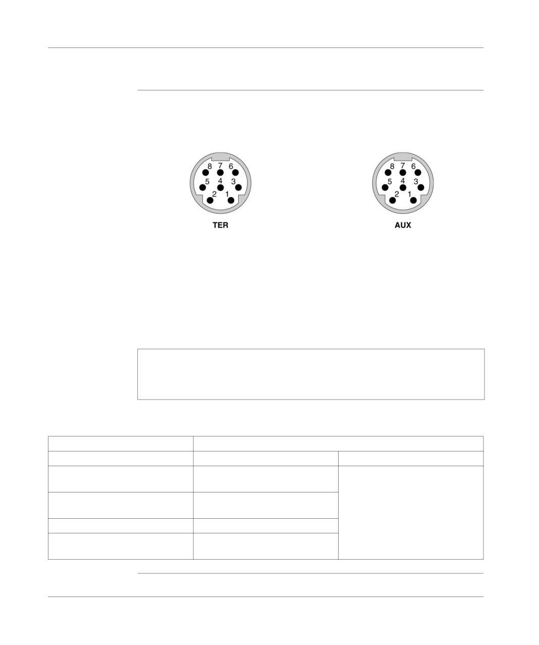
The terminal port connector is a lockable, 8-pin mini-DIN.
TSX 37-05/08/10 PLCs have a connector marked TER.
TSX 37-21 and TSX 37-22 PLCs have two connectors marked TER and AUX.
The signals are given below:
1
D(B)
1
D(B)
2
D(A)
2
D(A)
3
not connected
3
not connected
4
/DE
4
/DE
5
/DPT (1 = Uni-Telway master)
5
/DPT (1 = Uni-Telway master)
6
not connected
6
not connected
7
0V
7
0V
8
5V
8
Not connected
Note: The operation of the terminal port depends on two parameters:
the status of the signal/DPT (0 or 1), established by the wiring accessory (cable,
TSX P ACC 01),
the software configuration of the terminal port defined in PL7.
The table below defines the operating mode of the terminal port according to these
two parameters.
Configuration in PL7
Signal/DPT value
0
1
UNI-TELWAY master
Terminal port in UNI-TELWAY slave
Terminal port in UNI-TELWAY master
mode (default)
mode
UNI-TELWAY slave
Terminal port in UNI-TELWAY slave
mode
Character mode
Terminal port in character mode
Modbus/Jbus mode
Terminal port in Modbus/JBus mode
master/slave
TSX DM 37 xxE
343
Terminal port
344
TSX DM 37 xxE
TSX unit P ACC 01
32
Overview of this chapter
Aim of this
This chapter deals with the TSX unit P ACC 01.
chapter
What's in this
This Chapter contains the following Sections:
Chapter?
Section
Topic
Page
32.1
Hardware implementation
346
32.2
Examples of topology
354
TSX DM 37 xxE
345

TSX unit P ACC 01
32.1
Hardware implementation
Introduction to this Section
Aim of this
This Section describes in a general, then more detailed way, the unit
Section
TSX P ACC 01.
What's in this
This Section contains the following Maps:
Section?
Topic
Page
Standard functions
347
External appearance
348
Dimensions and settings
349
Internal view
350
Connection to UNI-TELWAY or Modbus buses
351
Connection to TSX 37 PLCs
352
Switch configuration
353
346
TSX DM 37 xxE
TSX unit P ACC 01
Standard functions
General
The TSX unit P ACC 01 is a wiring accessory which connects to the TER port of
PLC’s type TSX 37 by the intermediary of an integral cable equipped with a mini-DIN
connected at one end.
It makes it possible to :
connect several devices onto the terminal port of PLC’s type TSX 37-05/08/10. It
is therefore equipped with two mini-DIN ports, TER and AUX serigraph, they are
equivalent to those of PLC’s type TSX 37-••,
connect a TSX 37 PLC to the Modbus/Jbus bus,
insulate the UNI-TELWAY signals to extend the terminal port link of the PLC’s
type TSX 37-05/08/10 and TSX 37 2• more than 10 meters to connect the PLC
onto an UNI-TELWAY bus,
adapt the bus when the unit is connected to one end of the UNI-TELWAYou
Modbus bus,
fix the terminal port operation mode:
UNI-TELWAY master,
UNI-TELWAY slave, Modbus slave or character mode.
Note: The two ports of the unit TSX P ACC 01, TER and AUX are not insulated
from each other, nor from the TER port of thePLC which provides the supply.
TSX DM 37 xxE
347
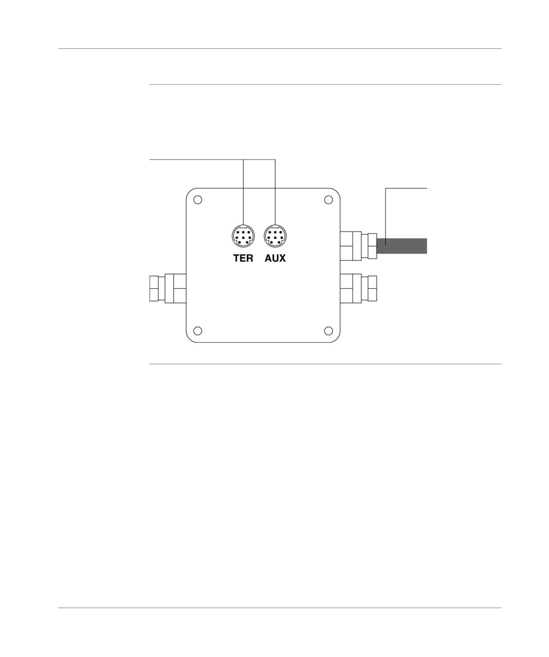
TSX unit P ACC 01
External appearance
General points
It is a zamak unit, the same type as the UNI-TELWAY connection or branching
devices (TSX SCA 50 and TSX SCA 62). It is to be mounted in a cabinet. Its
protection rating is IP20.
Terminal ports
Connection cable to TER port
for TSX 37 PLC (length 1 m)
348
TSX DM 37 xxE
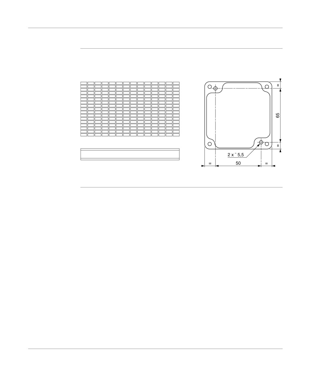
TSX unit P ACC 01
Dimensions and settings
General
The TSX P ACC 01 device is installed on a AM1-PA••• type perforated plate or on a
DIN rail with a LA9 D9976 fixing plate.
AM1-PA•••
AM1 DE/DP
TSX DM 37 xxE
349
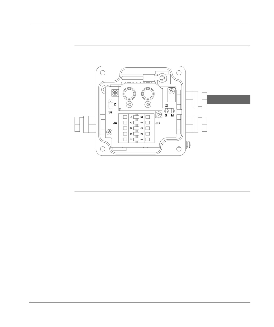
TSX unit P ACC 01
Internal view
Illustration
S1 Operating mode selection (slave or master),
S2 End of line adaptation
JA and JB Connecting terminal blocks to the UNI-TELWAY bus or to the Modbus/Jbus bus.
350
TSX DM 37 xxE
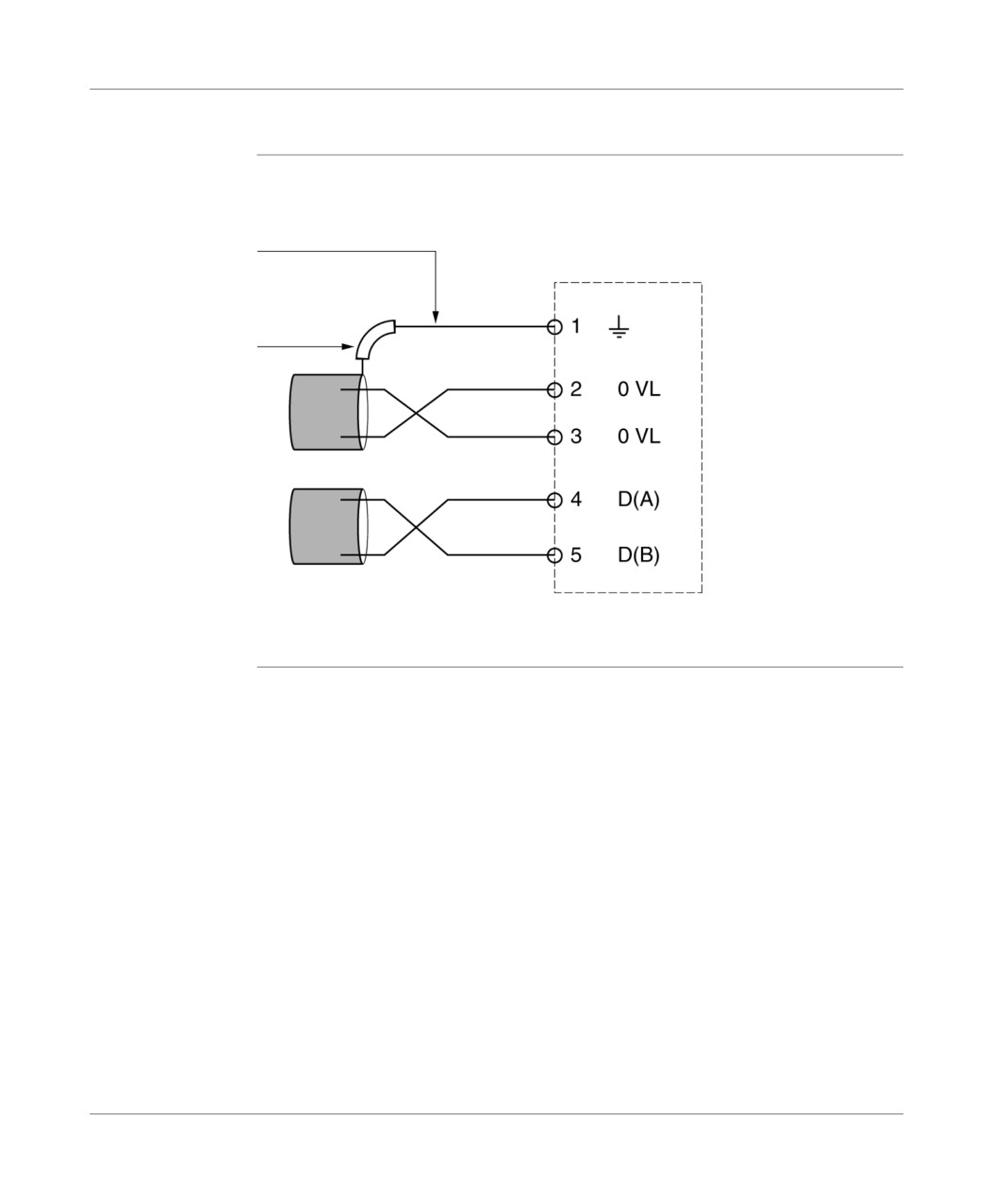
TSX unit P ACC 01
Connection to UNI-TELWAY or Modbus buses
General points
The TSX P ACC 01 device is connected to UNI-TELWAY or Modbus buses by the
connection terminal blocks JA and JB as shown below.
Shield
Insulating sleeve
(essential)
White
Red
White
Blue
TSX DM 37 xxE
351
TSX unit P ACC 01
Connection to TSX 37 PLCs
General
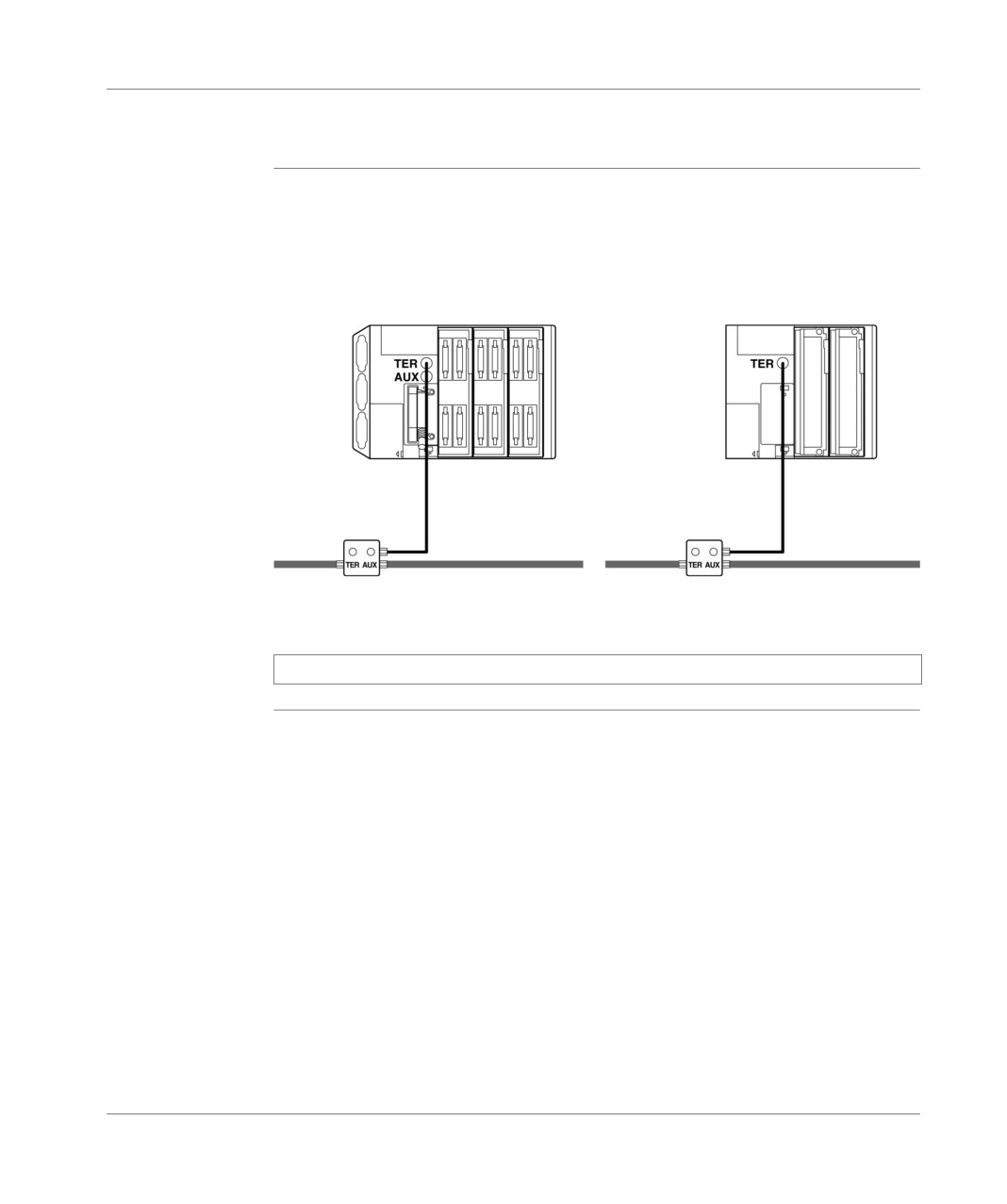
Before the TSX P ACC 01 device is supplied by the terminal port of the PLC, it must
be connected to the TER serigraph terminal port.
The device can be connected and disconnected automatically while switched on.
TSX 37-2•
TSX 37-10
TSX P ACC 01
TSX P ACC 01
Note: Only one TSX P ACC 01 device can be connected to a TSX 37 PLC.
352
TSX DM 37 xxE
TSX unit P ACC 01
Switch configuration
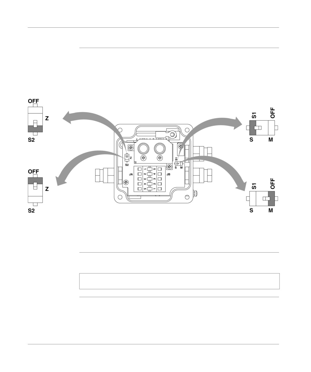
Configuration of The end of line adaptation is performed by using S2 as shown below:
line adaptation
Position of S2
UNI-TELWAY slave
if the device is located
Modbus Slave
at the end of the line
or character mode
Position of S2
UNI-TELWAY master
if the device is located in any
other position that at the end
of the line
Operating mode The operating mode is selected by using switch S1 as indicated below.
configuration
Note: The operating mode chosen only concerns the connection cable to the TER
connector of the PLC processor.
TSX DM 37 xxE
353

TSX unit P ACC 01
32.2
Examples of topology
Introduction to this Section
Aim of this
This Section contains different examples of topology.
Section
What's in this
This Section contains the following Maps:
Section?
Topic
Page
Connectable devices
355
Master UNI-TELWAY mode
356
Slave UNI-TELWAY mode
357
Modbus/JBus
358
Connection between two PLCs
359
TSX P ACC 01 connectors
360
354
TSX DM 37 xxE
TSX unit P ACC 01
Connectable devices
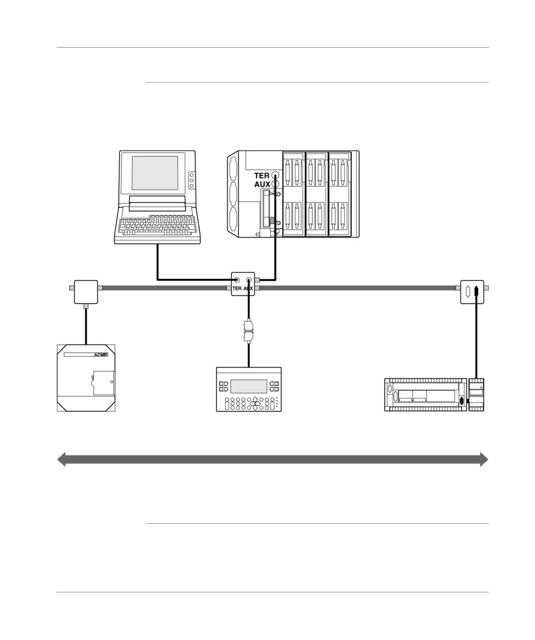
General points
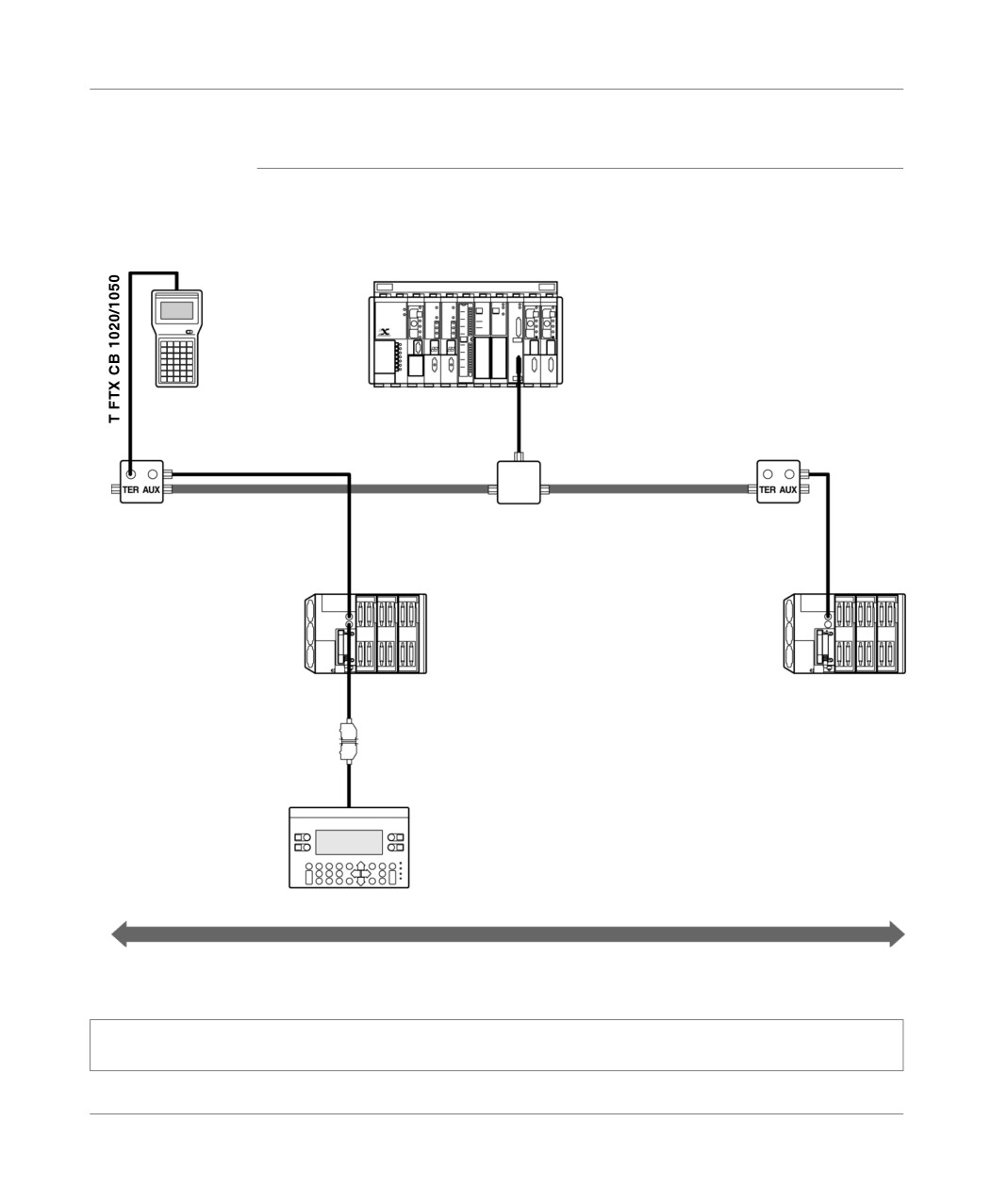
The functions of both ports on the TSX P ACC 01 device are identical to those of the
TER and AUX terminal ports on TSX 37-•• PLCs:
The device’s TER port allows all devices supporting the UNI-TELWAY protocol
to be connected, in particular devices which are not auto-supplied (programming
terminal FTX 117, converter cable RS 485/RS 232, etc.),
the device’s AUX port only allows the connection of auto-supplied devices
(operator dialog console, PLCs, third-party devices, etc.).
Note: The TSX P ACC 01 device is supplied by the TER port of the PLC to which
it is connected. Therefore, the terminal’s TER port allows the use of auto-supplied
devices (CCX 17, etc.) or devices which are not auto-supplied (programming
terminal FTX 117, converter cable RS 485/RS 232, etc.).
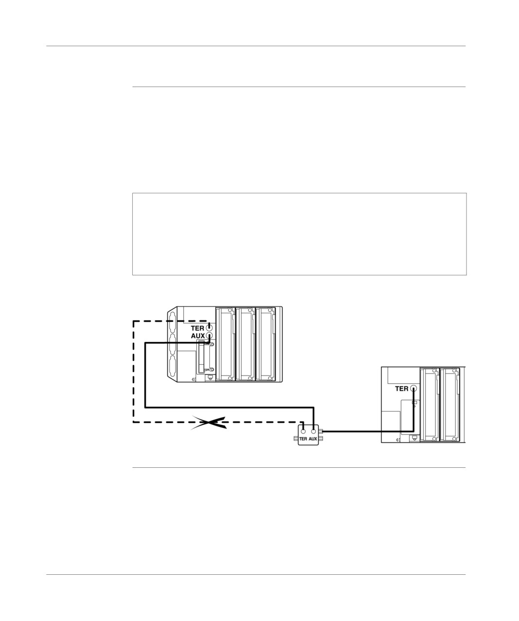
If you wish to connect the terminal port of a second PLC to one of the ports of the
TSX P ACC 01 device, you must use the AUX port (of the device and the PLC) so
as to avoid having any conflict between the power supplies of the two PLCs.
TSX 37-2• Master
TSX 37-10 Slave
T FTX CB 1020/1050
TSX P ACC 01
TSX DM 37 xxE
355
TSX unit P ACC 01
Master UNI-TELWAY mode
Example
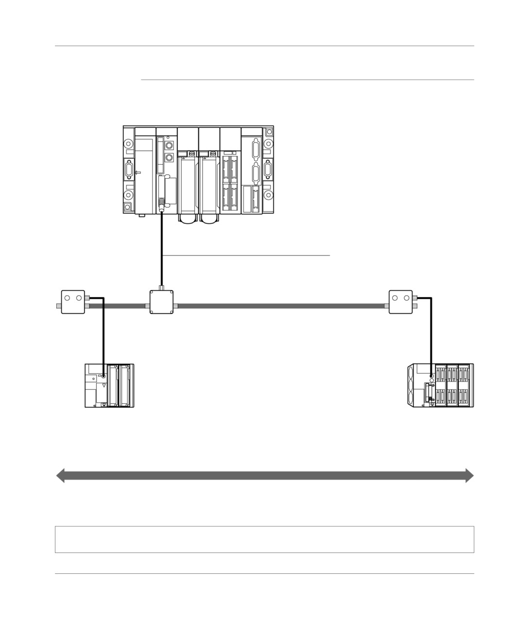
The way to connect a TSX P ACC 01 device to a master PLC of the UNI-TELWAY
link is shown in the example below:
FT 2100
TSX 37-•• Master
Address 1, 2, 3
UNI-TELWAY bus
TSX
TSX P
TSX
SCA 50
ACC 01
SCA 62
XBT-Z 968
ATV 16
T CCX CB10 002
CCX 17
TSX 17-20
Slave
Slave
Slave
Address 6
Address 4/5
Address 7/8
1000 m maximum
In this example, the S1 and S2 switches should be positioned to OFF (master mode
and device in a different position to end of line).
356
TSX DM 37 xxE
TSX unit P ACC 01
Slave UNI-TELWAY mode
Example
The way to connect a TSX P ACC 01 device to a slave PLC of the UNI-TELWAY link
is shown in the example below.
FTX 117
TSX 37-107 Master
TSX SCP CU 030
S1=ON
S1=ON
S2=ON
S2=ON
UNI-TELWAY bus
TSX P ACC 01
TSX SCA 50
TSX P ACC 01
TSX 37-••
Slave
XBT-Z 968
TSX 37-••
Slave
T CCX CB10 002
CCX 17
1000 m maximum
In this example, the S1 and S2 switches should be positioned to ON (slave mode
and device in end of line position).
Note: In order that a PLC can work in slave mode, it must be connected to a TSX P ACC 01 device by
a built-in cable.
TSX DM 37 xxE
357
TSX unit P ACC 01
Modbus/JBus
Example
The way to connect a TSX P ACC 01 device to a slave PLC of the UNI-TELWAY link
is shown in the example below:
TSX 57-••
TSX SCP 114
Master PCMCIA
communication
card
TSX SCP CM 4030
S1=ON
S1=ON
S2=ON
S2=ON
Modbus/JBus
TSX P
TSX SCA 50
TSX P ACC 01
ACC 01
TSX 37-10
TSX 37-2•
Slave
Slave
1000 m maximum
In this example, the S1 and S2 switches of the two devices should be positioned to
ON (slave mode and device in the end of line position).
Note: In order that a PLC can work in slave mode, it must be connected to a TSX P ACC 01 device by
a built-in cable.
358
TSX DM 37 xxE
TSX unit P ACC 01
Connection between two PLCs
Reminders
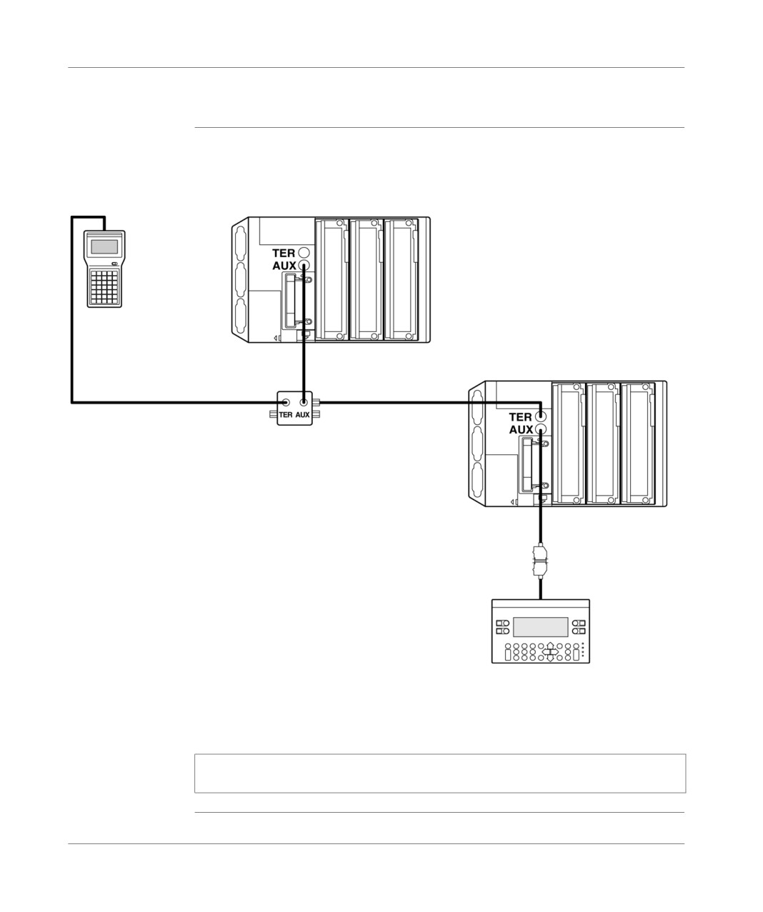
If you want to connect the terminal port of a second PLC to one of the ports of the
TSX P ACC 01 device, you must use the AUX port so as to avoid any conflict
between the power supplies of the two PLCs.
FTX 17
TSX 37-•• Maître
T FTX CB
S1=ON
1020/1050
TSX 37-•• Esclave
S2=Non significatif
T FTX CB 1020/1050
TSX P ACC 01
XBT-Z 968
T CCX CB10 002
CCX 17
In the example below, the TSX P ACC 01 device should be connected by built-in
cable to the UNI-TELWAY slave PLC. Its S1 switch should be positioned to ON.
As the S2 device is not on a UNI-TELWAY bus, the position of its switch is not
important.
Note: In order that a PLC can work in slave mode, it must be connected to a
TSX P ACC 01 device by a built-in cable.
TSX DM 37 xxE
359
TSX unit P ACC 01
TSX P ACC 01 connectors
General
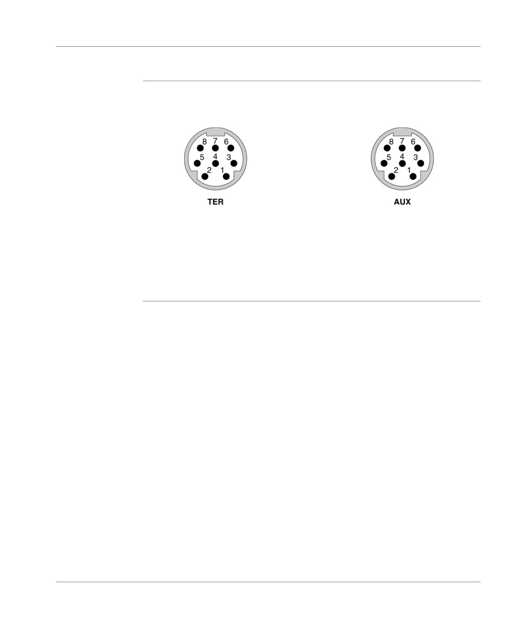
The TSX P ACC 01 device has two TER and AUX serigraph connectors.
The signals can be seen below :
1
D(B)
1
D(B)
2
D(A)
2
D(A)
3
not connected
3
not connected
4
not connected
4
not connected
5
not connected
5
not connected
6
not connected
6
not connected
7
0V
7
not connected
8
5V
8
not connected
360
TSX DM 37 xxE