Yamaha Grizzly YF70GG, YF70GPG, YF70GPSG. Service manual (2016) - part 13


  Главная      Manuals     Yamaha YF70GG, YF70GPG, YF70GPSG, YF70GPLG, YFM70GDXG, YFM70GDHG, YFM70GPXG, YFM70GPHG, YFM70GPSG, YFM70GPLG, YFM700FWAD. Service manual (2016)


Search            copyright infringement  


Content      ..     11      12      13      14     ..


Yamaha Grizzly YF70GG, YF70GPG, YF70GPSG. Service manual (2016) - part 13


-------------------------------------------------------------------------------------------------------------------------------------------------------------
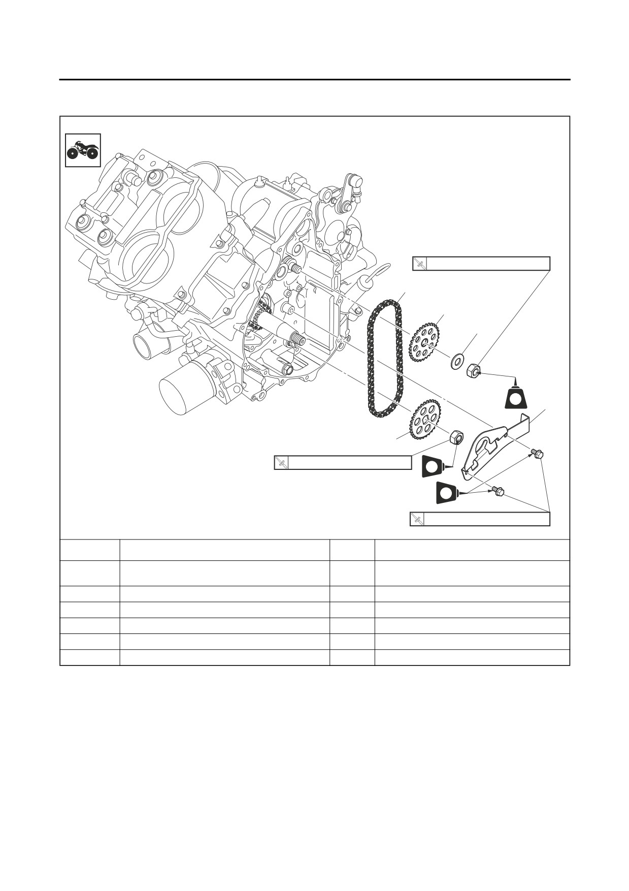
OIL PUMP SPROCKETS
EBS20114
OIL PUMP SPROCKETS
Removing the oil pump sprockets
25 Nm (2.5 mkgf, 18 ftIbf)
5
4
3
LT
1
2
25 Nm (2.5 mkgf, 18 ftIbf)
LT
LT
10 Nm (1.0 mkgf, 7.2 ftIbf)
Order
Job/Parts to remove
Qty
Remarks
Refer to “AC MAGNETO AND STARTER
AC magneto rotor
CLUTCH” on page 5-35.
1
Timing chain stopper guide (lower)
1
2
Oil pump driven sprocket
1
3
Washer
1
4
Oil pump drive sprocket
1
5
Chain
1
5-44

-------------------------------------------------------------------------------------------------------------------------------------------------------------

OIL PUMP SPROCKETS
EBS30524
TIP
REMOVING THE OIL PUMP DRIVE
Install the oil pump drive sprocket so that the
SPROCKET AND OIL PUMP DRIVEN
SPROCKET
protruding portion “a” of the sprocket is facing to-
ward the crankcase.
1. Loosen:
• Oil pump driven sprocket nut “1”
• Oil pump drive sprocket nut “2”
a
2
1
1
2. Install:
• Washer “1”
▼▼▼▼▼▼▼▼▼▼▼▼▼▼▼▼▼▼▼▼▼▼▼▼▼▼▼▼▼▼▼▼
• Oil pump drive sprocket nut
a. Temporarily install the AC magneto rotor.
TIP
Refer to “AC MAGNETO AND STARTER
CLUTCH” on page 5-35.
Install the washer with its rounded side “a” facing
b. Hold the AC magneto rotor “3” with the rotor
away from the crankcase.
holding tool “4” while loosening the oil pump
driven sprocket nut and oil pump drive
sprocket nut.
a
Rotor holding tool
90890-04166
YM-04166
1
3. Install:
• Oil pump driven sprocket “1”
• Chain “2”
• Oil pump driven sprocket nut
TIP
4
3
Install the oil pump driven sprocket with the
“23A” mark “a” facing out.
▲▲▲▲▲▲▲▲▲▲▲▲▲▲▲▲▲▲▲▲▲▲▲▲▲▲▲▲▲▲▲▲
EBS30525
CHECKING THE OIL PUMP SPROCKETS
1. Check:
1
2
• Oil pump drive sprocket
• Oil pump driven sprocket
Cracks/wear/damage → Replace.
a
EBS30526
INSTALLING THE OIL PUMP DRIVE
SPROCKET AND OIL PUMP DRIVEN
SPROCKET
4. Tighten:
1. Install:
• Oil pump drive sprocket nut “1”
• Oil pump drive sprocket “1”
• Oil pump driven sprocket nut “2”
5-45

-------------------------------------------------------------------------------------------------------------------------------------------------------------

OIL PUMP SPROCKETS
Oil pump drive sprocket nut
25 Nm (2.5 m·kgf, 18 ft·lbf)
LOCTITE®
Oil pump driven sprocket nut
25 Nm (2.5 m·kgf, 18 ft·lbf)
LOCTITE®
1
2
▼▼▼▼▼▼▼▼▼▼▼▼▼▼▼▼▼▼▼▼▼▼▼▼▼▼▼▼▼▼▼▼
a. Temporarily install the AC magneto rotor.
Refer to “AC MAGNETO AND STARTER
CLUTCH” on page 5-35.
b. Hold the AC magneto rotor “3” with the rotor
holding tool “4” while tightening the oil pump
drive sprocket nut and oil pump driven
sprocket nut.
Rotor holding tool
90890-04166
YM-04166
4
3
▲▲▲▲▲▲▲▲▲▲▲▲▲▲▲▲▲▲▲▲▲▲▲▲▲▲▲▲▲▲▲▲
5-46

-------------------------------------------------------------------------------------------------------------------------------------------------------------

SHIFT LEVER
EBS20042
SHIFT LEVER
Removing the shift levers and stopper lever
E
10 Nm (1.0 mkgf, 7.2 ftIbf)
5
2
New
LS
1
4
New
E
3
10 Nm (1.0 mkgf, 7.2 ftIbf)
LS
8
7
E
6
14 Nm (1.4 mkgf, 10 ftIbf)
Order
Job/Parts to remove
Qty
Remarks
Refer to “ENGINE REMOVAL (2)” on page
Drive select lever unit/shift arm
5-6.
1
Shift lever cover
1
2
Shift lever cover gasket
1
3
Dowel pin
1
4
Oil seal
1
5
Shift lever 1
1
6
Stopper lever spring
1
7
Shift lever 2
1
8
Stopper lever
1
5-47

-------------------------------------------------------------------------------------------------------------------------------------------------------------

SHIFT LEVER
EBS30163
CHECKING THE STOPPER LEVER
1. Check:
• Stopper lever
a
Damage/wear → Replace.
• Stopper lever spring
b
Damage/wear → Replace.
1
EBS30164
CHECKING THE SHIFT LEVERS
1. Check:
• Shift lever 1
3. Install:
• Shift lever 2
• Shift lever 1 “1”
Damage/wear → Replace.
TIP
EBS30165
When installing shift lever 1, align the alignment
INSTALLING THE SHIFT LEVERS
mark “a” on shift lever 1 with the punch marks “b”
1. Install:
on shift lever 2 “2”.
• Collar “1” (onto the stopper lever “2”)
• Shift lever 2 “3”
• Washer “4”
1
• Stopper spring “5”
TIP
a
• Make sure the projection “a” on the stopper le-
ver “2” facing toward the collar.
• Install the shift lever 2 “3” with the marks “b”
b
2
facing the stopper spring.
2
4.
Install:
1
• Oil seal “1”
New
b
(into the shift lever cover “2”)
4
Installed depth “a”
5
1.0-1.5 mm (0.04-0.06 in)
a
3
2. Install:
New
1
• Shift lever 2 assembly “1”
a
Shift lever 2 bolt
14 Nm (1.4 m·kgf, 10 ft·lbf)
2
TIP
Align the projection “a” on the shift drum with the
slit “b” in the stopper lever.
5-48

-------------------------------------------------------------------------------------------------------------------------------------------------------------

PRIMARY AND SECONDARY SHEAVES
EBS20043
PRIMARY AND SECONDARY SHEAVES
Removing the primary and secondary sheaves
New
10
10 Nm (1.0 mkgf, 7.2 ftIbf)
New
11
9
100 Nm (10.0 mkgf, 72 ftIbf)
6
8
10 Nm (1.0 mkgf, 7.2 ftIbf)
(8)
New
LS
7
4
2
New
4
5
(11)
3
1
140 Nm (14 mkgf, 100 ftlbf)
10 Nm (1.0 mkgf, 7.2 ftIbf)
LS
10 Nm (1.0 mkgf, 7.2 ftIbf)
Order
Job/Parts to remove
Qty
Remarks
Refer to “GENERAL CHASSIS (4)” on page
Footrest board (right)
4-11.
Refer to “ENGINE REMOVAL (1)” on page
V-belt cooling ducts
5-3.
1
Drive belt cover
1
2
Rubber gasket
1
3
Bearing housing
1
4
Dowel pin
2
5
Primary sheave assembly
1
6
V-belt
1
7
Primary fixed sheave
1
8
Secondary sheave assembly
1
9
Drive belt case
1
10
Rubber gasket
1
11
Rubber gasket
1
5-49

-------------------------------------------------------------------------------------------------------------------------------------------------------------

PRIMARY AND SECONDARY SHEAVES
Disassembling the primary sheave
* Apply Yamaha Grizzly grease or Yamaha grease F.
Order
Job/Parts to remove
Qty
Remarks
1
Primary sheave cap
1
2
Primary sheave slider
4
3
Primary sheave cam
1
4
Primary sheave weight
8
5
Spacer
1
6
Oil seal
2
7
Primary sliding sheave
1
8
O-ring
1
5-50

-------------------------------------------------------------------------------------------------------------------------------------------------------------

PRIMARY AND SECONDARY SHEAVES
Disassembling the secondary sheave
* Apply Yamaha grease H or POLYREX EM®
Order
Job/Parts to remove
Qty
Remarks
1
Secondary sheave spring retaining nut
1
2
Upper spring seat
1
3
Compression spring
1
4
Lower spring seat
1
5
Guide pin
4
6
Secondary sliding sheave
1
7
O-ring
2
8
Secondary fixed sheave
1
9
Oil seal
2
5-51

-------------------------------------------------------------------------------------------------------------------------------------------------------------

PRIMARY AND SECONDARY SHEAVES
EBS30167
REMOVING THE PRIMARY AND
Sheave fixed block
SECONDARY SHEAVES
90890-04135
1. Loosen:
Sheave fixed bracket
• Primary sheave assembly nut “1”
YM-04135
Locknut wrench
TIP
90890-01348
Use the rotor holding tool “2” to hold the primary
Locknut wrench
sheave.
YM-01348
Sheave spring compressor
Rotor holding tool
90890-04134
90890-04166
Sheave spring compressor
YM-04166
YM-04134
b.
Place the sheave fixed block in a vise and se-
cure it.
c.
Tighten the sheave spring compressor nut “5”
2
and compress the spring.
d.
Loosen the secondary sheave spring retain-
ing nut “1” with the locknut wrench “3”.
e.
Remove the secondary sheave spring retain-
1
ing nut “1”.
f.
Remove the sheave spring compressor and
locknut wrench.
2. Loosen:
• Secondary sheave assembly nut “1”
TIP
5
4
1
Shift the transmission into “R” (reverse), set the
parking brake, and then loosen the secondary
3
sheave assembly nut.
1
EBS30168
DISASSEMBLING THE SECONDARY
2
SHEAVE
1. Remove:
• Secondary sheave spring retaining nut “1”
▼▼▼▼▼▼▼▼▼▼▼▼▼▼▼▼▼▼▼▼▼▼▼▼▼▼▼▼▼▼▼▼
a. Attach the sheave fixed block “2”, locknut
wrench “3” and sheave spring compressor “4”
to the secondary sheave assembly.
5-52

-------------------------------------------------------------------------------------------------------------------------------------------------------------

PRIMARY AND SECONDARY SHEAVES
2. Check:
• Primary sliding sheave
• Primary fixed sheave
Cracks/damage → Replace.
EBS30171
CHECKING THE PRIMARY SHEAVE
WEIGHTS
The following procedure applies to all of the pri-
mary sheave weights.
1. Check:
▲▲▲▲▲▲▲▲▲▲▲▲▲▲▲▲▲▲▲▲▲▲▲▲▲▲▲▲▲▲▲▲
• Primary sheave weight
EBS30169
Cracks/damage/wear → Replace.
CHECKING THE V-BELT
2. Measure:
1. Check:
• Primary sheave weight outside diameter “a”
• V-belt “1”
Out of specification → Replace.
Cracks/damage/wear → Replace.
Primary sheave weight outside
Grease/oil → Clean the primary and second-
diameter
ary sheaves.
30 mm (1.18 in)
2. Measure:
Limit
• V-belt width “a”
29.5 mm (1.16 in)
Out of specification → Replace.
V-belt width limit
31.3 mm (1.23 in)
EBS30172
CHECKING THE PRIMARY SHEAVE
SLIDERS
The following procedure applies to all of the pri-
EBS30170
mary sheave sliders.
CHECKING THE PRIMARY SHEAVE
1. Check:
1. Check:
• Primary sheave slider
• Primary sliding sheave splines
Cracks/damage/wear → Replace.
Wear/cracks/damage → Replace.
• Primary sheave cam
EBS30173
Cracks/damage → Replace.
CHECKING THE SECONDARY SHEAVE
1. Check:
• Secondary fixed sheave
• Secondary sliding sheave
Cracks/damage/wear → Replace the sec-
ondary fixed and sliding sheaves as a set.
2. Check:
• Torque cam grooves “1”
Damage/wear → Replace the secondary
fixed and sliding sheaves as a set.
5-53

-------------------------------------------------------------------------------------------------------------------------------------------------------------

PRIMARY AND SECONDARY SHEAVES
3. Check:
• Guide pins “2”
Damage/wear → Replace the secondary
fixed and sliding sheaves as a set.
2. Install:
• Oil seals “1”
New
(into the primary sliding sheave “2”)
4.
Check:
Installed depth “a”
• Secondary sheave spring
0 mm (0 in)
Damage → Replace.
5.
Measure:
New
1
• Secondary sheave spring free length “a”
Out of specification → Replace the second-
ary sheave spring.
a
a
Free length
130.6 mm (5.14 in)
Limit
128.0 mm (5.04 in)
2
1
New
3. Lubricate:
• Spacer inner surface
• Primary sliding sheave inner surface
Recommended lubricant
Yamaha Grizzly grease or
Yamaha grease F
TIP
• Apply Yamaha Grizzly grease or Yamaha
EBS30174
grease F (2.5 g) to the inner surface of the
ASSEMBLING THE PRIMARY SHEAVE
spacer.
1. Clean:
• Apply Yamaha Grizzly grease or Yamaha
• Primary sliding sheave “1”
grease F (2.5 g) to the inner surface of the pri-
• Spacer “2”
mary sliding sheave.
• Primary sheave weights “3”
• Primary sheave cam
TIP
Remove any excess grease.
5-54

-------------------------------------------------------------------------------------------------------------------------------------------------------------

PRIMARY AND SECONDARY SHEAVES
4. Install:
• Primary sheave weights “1”
TIP
Apply Yamaha Grizzly grease or Yamaha
grease F (90 g) to the whole outer surface of the
weights and install.
3. Install:
• Secondary sliding sheave
4. Install:
• Guide pins “1”
EBS30175
ASSEMBLING THE SECONDARY SHEAVE
1. Install:
• Oil seals “1”
New
(into the secondary sliding sheave “2”)
Installed depth “a”
0 mm (0 in)
5. Lubricate:
• Guide pin grooves “1”
2
(with the recommended lubricant)
1
New
Recommended lubricant
Yamaha grease H or POLYREX
a
EM®
a
TIP
Apply Yamaha grease H or POLYREX EM® (5.0
New
1
g) to the guide pin grooves.
2. Lubricate:
• Secondary sliding sheave “1”
• Secondary fixed sheave “2”
(with the recommended lubricant)
Recommended lubricant
Yamaha grease H or POLYREX
EM®
TIP
Apply Yamaha grease H or POLYREX EM® (15
6. Install:
g) to the inner surfaces of the secondary
• Lower spring seat “1”
sheaves.
• Compression spring “2”
• Upper spring seat “3”
• Secondary sheave spring retaining nut “4”
5-55

-------------------------------------------------------------------------------------------------------------------------------------------------------------

PRIMARY AND SECONDARY SHEAVES
▼▼▼▼▼▼▼▼▼▼▼▼▼▼▼▼▼▼▼▼▼▼▼▼▼▼▼▼▼▼▼▼
a.
Attach the sheave fixed block “5”, locknut
a
wrench “6” and sheave spring compressor “7”
4
to the secondary sheave.
Sheave fixed block
90890-04135
Sheave fixed bracket
YM-04135
Locknut wrench
90890-01348
Locknut wrench
e. Remove the sheave spring compressor, lock-
YM-01348
nut wrench, and sheave fixed block.
Sheave spring compressor
▲▲▲▲▲▲▲▲▲▲▲▲▲▲▲▲▲▲▲▲▲▲▲▲▲▲▲▲▲▲▲▲
90890-04134
Sheave spring compressor
EBS30176
INSTALLING THE PRIMARY AND
YM-04134
SECONDARY SHEAVES
b.
Place the sheave fixed block in a vise and se-
1. Install:
cure it.
• Secondary sheave
c.
Tighten the sheave spring compressor nut “8”
• V-belt
and compress the spring.
• Primary fixed sheave
d.
Install the secondary sheave spring retaining
• Primary sheave
nut “4” and tighten it to specification using the
• Washer
locknut wrench.
• Nuts
TIP
Secondary sheave spring retain-
• Be sure to push in the primary sheave cam “1”
ing nut
when installing the primary sheave so that the
90 Nm (9.0 m·kgf, 65 ft·lbf)
primary sheave weights “2” will be properly po-
sitioned “a”.
TIP
• Install the washer “3” with its rounded side “b”
Install the secondary sheave spring retaining nut
facing away from the primary shave assembly.
“4” with its tapered side “a” facing the secondary
• Tightening the bolts “4” (90101-06016) will
sheaves.
push the secondary sliding sheave away,
causing the gap between the secondary fixed
and sliding sheaves to widen.
• Install the V-belt so that its arrow points in the
8
direction of rotation as shown in the illustration.
7
4
1
6
3
2
2
a
1
5
5-56

-------------------------------------------------------------------------------------------------------------------------------------------------------------

PRIMARY AND SECONDARY SHEAVES
A
2
b
3
4
3
1
B
2
4
4
3
1
A. Correct position
B. Incorrect position
3. Tighten:
• Primary sheave assembly nut “1”
Primary sheave assembly nut
140 Nm (14 m·kgf, 100 ft·lbf)
TIP
Use the rotor holding tool “2” to hold the primary
sheave.
2. Check:
• Primary sheave weights position
Rotor holding tool
Out of specification → Repeat step (1).
90890-04166
TIP
YM-04166
To check that the primary sheave weights “1”
are installed correctly, make sure that the sec-
ondary sheave “2”, primary sheave “3”, and V-
belt “4” are positioned as shown in the illustra-
tion.
2
1
4. Tighten:
• Secondary sheave assembly nut “1”
Secondary sheave assembly nut
100 Nm (10 m·kgf, 72 ft·lbf)
5-57

-------------------------------------------------------------------------------------------------------------------------------------------------------------

PRIMARY AND SECONDARY SHEAVES
TIP
Shift the transmission into “L” (low) or “H” (high),
set the parking brake, and then tighten the sec-
ondary sheave assembly nut.
1
5. Lubricate:
• Bearing housing bearing inner surface and
ball
(with the recommended lubricant)
Recommended lubricant
Shell Sunlight Grease 3®
TIP
Apply 2.3 g or more of Shell Sunlight Grease 3®
to the bearing inner surface and ball as shown in
the illustration.
5-58

-------------------------------------------------------------------------------------------------------------------------------------------------------------

CLUTCH
EBS20044
CLUTCH
Removing the clutch
190 Nm (19 mkgf, 137 ftlbf)
5
10 Nm (1.0 mkgf, 7.2 ftIbf)
4
New
2
1
3
3
(7)
E
E
E
LS
Order
Job/Parts to remove
Qty
Remarks
Refer to “PRIMARY AND SECONDARY
Drive belt case
SHEAVES” on page 5-49.
1
Clutch housing assembly
1
2
Clutch housing assembly gasket
1
3
Dowel pin
2
4
Clutch carrier assembly nut
1
Left-hand thread
5
Clutch carrier assembly
1
5-59

-------------------------------------------------------------------------------------------------------------------------------------------------------------

CLUTCH
Disassembling the clutch housing assembly
6
New
7
9
8
E
Order
Job/Parts to remove
Qty
Remarks
1
Oil seal
1
2
Circlip
1
3
Bearing housing
1
4
Circlip
1
5
Bearing
1
6
Seal ring
1
7
One-way clutch bearing
1
8
Bearing
1
9
Clutch housing
1
5-60

-------------------------------------------------------------------------------------------------------------------------------------------------------------

CLUTCH
EBS30177
• One-way clutch bearing
REMOVING THE CLUTCH
Chafing/wear/damage → Replace.
1. Remove:
TIP
• Clutch housing assembly
• Replace the one-way clutch bearing and clutch
TIP
housing as a set.
Working in crisscross pattern, loosen each bolt
• The one-way clutch bearing must be installed
1/4 of a turn. Remove them after all of them are
with the flange side facing inward.
loosened.
2. Check:
• One-way clutch operation
▼▼▼▼▼▼▼▼▼▼▼▼▼▼▼▼▼▼▼▼▼▼▼▼▼▼▼▼▼▼▼▼
a. Install the one-way clutch bearing and clutch
carrier assembly to the clutch housing and
hold the clutch carrier assembly.
b. When turning the clutch housing clockwise
“A”, it should turn freely; otherwise, the one-
way clutch assembly is faulty and must be re-
placed.
c. When turning the clutch housing counter-
2. Straighten:
clockwise “B”, the clutch housing and crank-
• Punched portion “a” of the clutch carrier as-
shaft should engage; otherwise, the one-way
sembly nut “1”
clutch assembly is faulty and must be re-
3. Remove:
placed.
• Clutch carrier assembly nut “1”
ECB01710
NOTICE
The clutch carrier assembly nut has left-
hand threads. To loosen the clutch carrier
assembly nut, turn it clockwise.
TIP
Use a universal clutch holder “2” to hold the
clutch carrier assembly.
▲▲▲▲▲▲▲▲▲▲▲▲▲▲▲▲▲▲▲▲▲▲▲▲▲▲▲▲▲▲▲▲
Universal clutch holder
90890-04086
EBS30179
Universal clutch holder
CHECKING THE CLUTCH SHOE
YM-91042
1. Check:
• Clutch shoe
Damage/wear → Replace.
2
Glazed areas → Sand with coarse sandpa-
a
per.
TIP
After sanding the glazed areas, clean the clutch
with a cloth.
2. Measure:
• Clutch shoe thickness
1
Out of specification → Replace.
EBS30178
Clutch shoe thickness limit
CHECKING THE CLUTCH
1.0 mm (0.04 in)
1. Check:
• Clutch housing
Damage/wear → Replace.
5-61

-------------------------------------------------------------------------------------------------------------------------------------------------------------

CLUTCH
a
1
New
2
a. Clutch shoe wear limit
EBS30181
INSTALLING THE CLUTCH
EBS30180
1. Install:
ASSEMBLING THE CLUTCH HOUSING
• Clutch carrier assembly
1. Install:
• Bearing “1”
• Clutch carrier assembly nut “1”
New
(into the clutch housing “2”)
Clutch carrier assembly nut
190 Nm (19 m·kgf, 137 ft·lbf)
Installed depth “a”
2.5-2.7 mm (0.10-0.11 in)
ECB01720
NOTICE
a
The clutch carrier assembly nut has left-
hand threads. To tighten the clutch carrier
assembly nut, turn it counterclockwise.
2
TIP
• Lubricate the threads of the clutch carrier as-
sembly nut with engine oil.
1
• Use a universal clutch holder “2” to hold the
clutch carrier assembly.
2. Install:
Universal clutch holder
• One-way clutch bearing
90890-04086
TIP
Universal clutch holder
The one-way clutch bearing should be installed
YM-91042
in the clutch housing with the “OUT SIDE” mark
2. Lock the threads with a drift punch.
“a” facing the clutch housing.
2
1 New
3. Install:
3. Install:
• Dowel pins “1”
• Oil seal “1”
New
• Gasket
New
(into the bearing housing “2”)
• Clutch housing assembly
Installed depth “a”
Clutch housing assembly bolt
0 mm (0 in)
10 Nm (1.0 m·kgf, 7.2 ft·lbf)
5-62

-------------------------------------------------------------------------------------------------------------------------------------------------------------

CLUTCH
TIP
• Tighten the bolts in stages, using a crisscross
pattern.
• After tightening the bolts, check that the clutch
housing assembly rotates smoothly.
1
5-63


Content      ..     11      12      13      14     ..