Yamaha Grizzly YF70GG, YF70GPG, YF70GPSG. Service manual (2016) - part 11
-------------------------------------------------------------------------------------------------------------------------------------------------------------
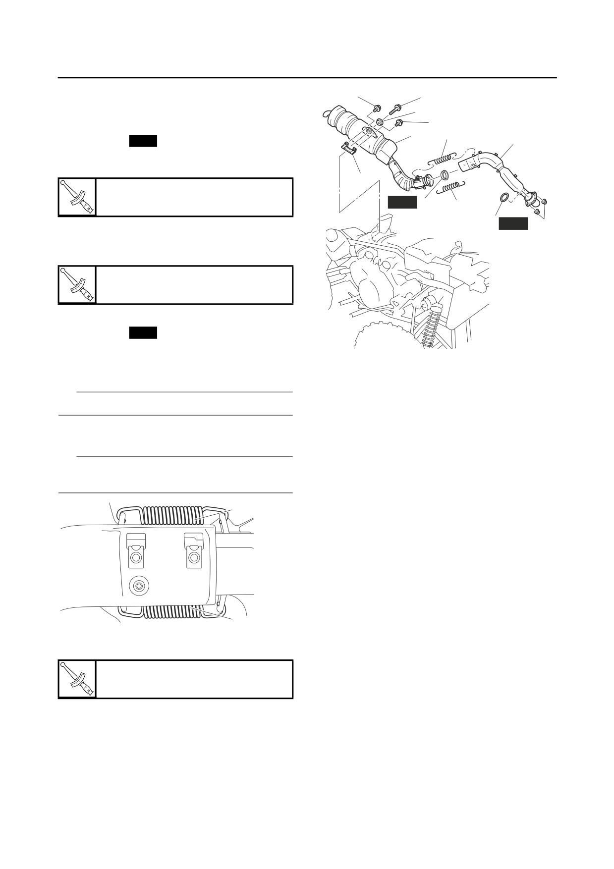
ENGINE REMOVAL (1)
EBS30127
INSTALLING THE EXHAUST PIPE AND
5
9
MUFFLER
8
1. Install:
5
7
10
• Gasket “1”
New
2
• Exhaust pipe “2”
• Exhaust pipe nuts “3”
4
Exhaust pipe nut
20 Nm (2.0 m·kgf, 14 ft·lbf)
New
6
10
1
New
3
2. Install:
• Muffler bracket “4”
• Muffler bracket bolts “5”
Muffler bracket bolt
20 Nm (2.0 m·kgf, 14 ft·lbf)
3. Install:
• Gasket “6”
New
• Muffler “7”
• Washer “8”
• Muffler bolt “9”
EBS30554
INSTALLING THE V-BELT COOLING DUCTS
TIP
1. Install:
Do not fully tighten the muffler bolt.
• V-belt cooling intake duct joint “1”
4. Install:
• V-belt cooling intake duct “2”
• Springs “10”
▼▼▼▼▼▼▼▼▼▼▼▼▼▼▼▼▼▼▼▼▼▼▼▼▼▼▼▼▼▼▼▼
a. Position the V-belt cooling intake duct joint
TIP
with its arrow mark “a” pointing toward the en-
Install the springs so that the spring ends are
gine.
pointing inward as shown in the illustration.
b. Align the projection on the V-belt cooling in-
take duct joint with the rib on the crankcase in
10
the area “b” shown in the illustration.
c. Align the screw head with the seam on the V-
belt cooling intake duct joint in the area “c”
shown in the illustration.
d. Align the projection on the V-belt cooling in-
take duct with the projection on the V-belt
cooling intake duct joint in the area “d” shown
in the illustration.
10
e. Align the bend in the screw clamp with the
5. Tighten:
projection on the V-belt cooling intake duct
• Muffler bolt “9”
joint in the area “e” shown in the illustration.
Muffler bolt
33 Nm (3.3 m·kgf, 24 ft·lbf)
5-4