Yamaha Grizzly YF70GG, YF70GPG, YF70GPSG. Service manual (2016) - part 9


  Главная      Manuals     Yamaha YF70GG, YF70GPG, YF70GPSG, YF70GPLG, YFM70GDXG, YFM70GDHG, YFM70GPXG, YFM70GPHG, YFM70GPSG, YFM70GPLG, YFM700FWAD. Service manual (2016)


Search            copyright infringement  


Content      ..     7      8      9      10     ..


Yamaha Grizzly YF70GG, YF70GPG, YF70GPSG. Service manual (2016) - part 9


-------------------------------------------------------------------------------------------------------------------------------------------------------------
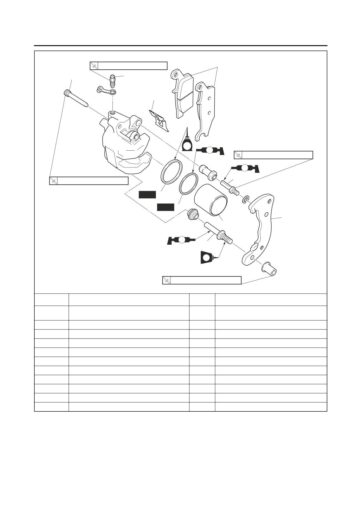
REAR BRAKE
Disassembling the rear brake calipers
5 Nm (0.5 mkgf, 3.6 ftIbf)
2
1
10
3
BF
S
17 Nm (1.7 mkgf, 12 ftIbf)
S
5
17 Nm (1.7 mkgf, 12 ftIbf)
New
9
New
8
4
7
S
6
LT
22 Nm (2.2 mkgf, 16 ftIbf)
Order
Job/Parts to remove
Qty
Remarks
The following procedure applies to both of
the rear brake calipers.
1
Brake pad holding bolt
1
2
Brake pad
2
3
Brake pad spring
1
4
Brake caliper bracket
1
5
Brake caliper guide pin
1
6
Brake caliper retaining pin
1
7
Brake caliper piston
1
8
Brake caliper dust seal
1
9
Brake caliper piston seal
1
10
Bleed screw
1
4-42

-------------------------------------------------------------------------------------------------------------------------------------------------------------

REAR BRAKE
EBS30382
Refer to “CHECKING THE FRONT BRAKE
INTRODUCTION
DISCS” on page 4-31.
EWB02930
WARNING
Brake disc thickness limit
Disc brake components rarely require disas-
3.0 mm (0.12 in)
sembly. Therefore, always follow these pre-
ventive measures:
5. Adjust:
• Never disassemble brake components un-
• Brake disc deflection
less absolutely necessary.
Refer to “CHECKING THE FRONT BRAKE
• If any connection on the hydraulic brake
DISCS” on page 4-31.
system is disconnected, the entire brake
system must be disassembled, drained,
Rear brake disc bolt
30 Nm (3.0 m·kgf, 22 ft·lbf)
cleaned, properly filled, and bled after reas-
LOCTITE®
sembly.
• Never use solvents on internal brake com-
6. Install:
ponents.
Rear wheels
• Use only clean or new brake fluid for clean-
Refer to “REAR WHEELS” on page 4-23.
ing brake components.
• Brake fluid may damage painted surfaces
EBS30384
and plastic parts. Therefore, always clean
REPLACING THE REAR BRAKE PADS
up any spilt brake fluid immediately.
The following procedure applies to both brake
• Avoid brake fluid coming into contact with
calipers.
the eyes as it can cause serious injury.
TIP
FIRST AID FOR BRAKE FLUID ENTERING
When replacing the brake pads, it is not neces-
THE EYES:
sary to disconnect the brake hose or disassem-
• Flush with water for 15 minutes and get im-
ble the brake caliper.
mediate medical attention.
1. Measure:
EBS30383
• Brake pad wear limit “a”
CHECKING THE REAR BRAKE DISCS
Out of specification → Replace the brake
The following procedure applies to both brake
pads and brake pad spring as a set.
discs.
Brake pad lining thickness limit
1. Remove:
1.0 mm (0.04 in)
• Rear wheel
Refer to “REAR WHEELS” on page 4-23.
2. Check:
• Brake disc
Damage/galling → Replace.
3. Measure:
• Brake disc deflection
a
Out of specification → Correct the brake disc
deflection or replace the brake disc.
Refer to “CHECKING THE FRONT BRAKE
DISCS” on page 4-31.
2. Install:
Brake disc deflection limit
• Brake pad spring
0.10 mm (0.0039 in)
• Brake pads
4. Measure:
TIP
• Brake disc thickness
Always install new brake pads and a new brake
Measure the brake disc thickness at a few dif-
pad spring as a set.
ferent
locations.
Out of specification → Replace.
4-43

-------------------------------------------------------------------------------------------------------------------------------------------------------------

REAR BRAKE
▼▼▼▼▼▼▼▼▼▼▼▼▼▼▼▼▼▼▼▼▼▼▼▼▼▼▼▼▼▼▼▼
• Brake lever bracket
a. Connect a clear plastic hose “1” tightly to
ECB02880
the bleed screw “2”. Put the other end of the
NOTICE
hose into an open container.
The brake lever pivot bolt and nut have left-
handed threads. To loosen the pivot bolt and
nut, turn them clockwise.
EBS30386
DISASSEMBLING THE REAR BRAKE
CALIPERS
1
The following procedure applies to both of the
brake calipers.
2
TIP
Before disassembling the brake caliper, drain
b. Loosen the bleed screw and push the brake
the brake fluid from the entire brake system.
caliper piston into the brake caliper with
1. Remove:
your finger.
• Brake caliper piston “1”
c. Tighten the bleed screw.
• Brake caliper dust seal “2”
Brake caliper bleed screw
• Brake caliper piston seal “3”
5 Nm (0.5 m·kgf, 3.6 ft·lbf)
d. Install new brake pads and a new brake pad
spring.
▲▲▲▲▲▲▲▲▲▲▲▲▲▲▲▲▲▲▲▲▲▲▲▲▲▲▲▲▲▲▲▲
3. Install:
• Brake pad holding bolt
• Brake pad holding bolt plug
3
• Brake caliper
2
1
Brake pad holding bolt
▼▼▼▼▼▼▼▼▼▼▼▼▼▼▼▼▼▼▼▼▼▼▼▼▼▼▼▼▼▼▼▼
17 Nm (1.7 m·kgf, 12 ft·lbf)
a. Blow compressed air into the brake hose
Brake pad holding bolt plug
joint opening “a” to force out the piston from
2.5 Nm (0.25 m·kgf, 1.8 ft·lbf)
the brake caliper.
Rear brake caliper bolt
EWB02890
30 Nm (3.0 m·kgf, 22 ft·lbf)
WARNING
• Cover the brake caliper piston with a rag.
4. Check:
Be careful not to get injured when the pis-
• Brake fluid level
ton is expelled from the brake caliper.
Below the minimum level mark → Add the
• Never try to pry out the brake caliper pis-
specified brake fluid to the proper level.
ton.
Refer to “CHECKING THE BRAKE FLUID
LEVEL” on page 3-14.
5. Check:
• Brake lever and pedal operation
Soft or spongy feeling → Bleed the brake sys-
tem.
Refer to “BLEEDING THE HYDRAULIC
BRAKE SYSTEM” on page 3-14.
a
EBS30385
REMOVING THE REAR BRAKE MASTER
CYLINDER
b. Remove the brake caliper dust seal and
1. Remove:
brake caliper piston seal.
• Brake lever
▲▲▲▲▲▲▲▲▲▲▲▲▲▲▲▲▲▲▲▲▲▲▲▲▲▲▲▲▲▲▲▲
4-44

-------------------------------------------------------------------------------------------------------------------------------------------------------------

REAR BRAKE
EBS30387
• Never use solvents on internal brake com-
CHECKING THE REAR BRAKE CALIPERS
ponents as they will cause the brake caliper
The following procedure applies to both of the
piston dust seals and brake caliper piston
brake calipers.
seals to swell and distort.
Recommended brake component replacement
• Whenever a brake caliper is disassembled,
schedule
replace the brake caliper piston dust seals
Brake pads
If necessary
and brake caliper piston seals.
Piston seals, dust seals
Every two years
Brake hoses
Every four years
Specified brake fluid
DOT 4
Every two years and
Brake fluid
whenever the brake is
EBS30389
disassembled
INSTALLING THE REAR BRAKE CALIPERS
1. Check:
The following procedure applies to both of the
• Brake caliper piston “1”
brake calipers.
Rust/scratches/wear → Replace the brake
1. Install:
caliper piston.
• Brake caliper assembly
• Brake caliper cylinder “2”
• Brake caliper bolts “1”
Scratches/wear → Replace the brake caliper
• Brake hose “2”
assembly.
• Copper washers “3”
New
• Brake caliper body “3”
• Brake hose union bolt “4”
Cracks/damage → Replace the brake caliper
assembly.
Rear brake caliper bolt
30 Nm (3.0 m·kgf, 22 ft·lbf)
• Brake fluid delivery passages
Brake hose union bolt
(brake caliper body)
27 Nm (2.7 m·kgf, 20 ft·lbf)
Obstruction → Blow out with compressed air.
EWB03140
EWB02870
WARNING
WARNING
Whenever a brake caliper is disassembled,
Proper brake hose routing is essential to in-
replace the brake caliper piston dust seals
sure safe vehicle operation.
and brake caliper piston seals.
Refer to “CABLE ROUTING” on page 2-33.
ECB02330
3
NOTICE
When installing the brake hose onto the
brake caliper, make sure the brake pipe
touches the projection “a” on the brake cali-
per.
2
1
2
EBS30388
ASSEMBLING THE REAR BRAKE CALIPERS
1
The following procedure applies to both of the
brake calipers.
a
EWB03150
4
WARNING
1
3
New
• Before installation, all internal brake com-
ponents should be cleaned and lubricated
2. Fill:
with clean or new brake fluid.
• Brake master cylinder reservoir
(with the specified amount of the specified
brake fluid)
4-45

-------------------------------------------------------------------------------------------------------------------------------------------------------------

REAR BRAKE
3. Check:
Specified brake fluid
• Brake master cylinder reservoir
DOT 4
Cracks/damage → Replace.
• Brake master cylinder reservoir diaphragm
EWB02790
Cracks/damage → Replace.
WARNING
4. Check:
• Use only the designated brake fluid. Other
• Brake hoses
brake fluids may cause the rubber seals to
Cracks/damage/wear → Replace.
deteriorate, causing leakage and poor
brake performance.
EBS30391
• Refill with the same type of brake fluid that
ASSEMBLING THE REAR BRAKE MASTER
is already in the system. Mixing brake fluids
CYLINDER
EWB03590
may result in a harmful chemical reaction,
WARNING
leading to poor brake performance.
• Before installation, all internal brake com-
• When refilling, be careful that water does
ponents should be cleaned and lubricated
not enter the brake fluid reservoir. Water
with clean or new brake fluid.
will significantly lower the boiling point of
• Never use solvents on internal brake com-
the brake fluid and could cause vapor lock.
ponents.
ECB01320
• Whenever a master cylinder is disassem-
NOTICE
bled, replace the brake master cylinder kit.
Brake fluid may damage painted surfaces
and plastic parts. Therefore, always clean up
Specified brake fluid
any spilt brake fluid immediately.
DOT 4
3. Bleed:
• Brake system
EBS30392
Refer to “BLEEDING THE HYDRAULIC
INSTALLING THE REAR BRAKE MASTER
BRAKE SYSTEM” on page 3-14.
CYLINDER
4. Check:
1. Install:
• Brake fluid level
• Brake master cylinder “1”
Below the minimum level mark → Add the
• Brake master cylinder holder “2”
specified brake fluid to the proper level.
Rear brake master cylinder hold-
Refer to “CHECKING THE BRAKE FLUID
er bolt
LEVEL” on page 3-14.
7 Nm (0.7 m·kgf, 5.1 ft·lbf)
5. Check:
• Brake lever and pedal operation
TIP
Soft or spongy feeling → Bleed the brake sys-
• Align the end of the brake master cylinder hold-
tem.
er with the punch mark “a” on the handlebar.
Refer to “BLEEDING THE HYDRAULIC
• Install the brake master cylinder holder with the
BRAKE SYSTEM” on page 3-14.
“UP” mark “b” facing up.
EBS30390
• First, tighten the upper bolt, then the lower bolt.
CHECKING THE REAR BRAKE MASTER
CYLINDER
1
1. Check:
• Brake master cylinder
Damage/scratches/wear → Replace.
• Brake fluid delivery passages
(brake master cylinder body)
Obstruction → Blow out with compressed air.
a
2. Check:
2
• Brake master cylinder kit
b
Damage/scratches/wear → Replace.
2. Install:
• Brake hose
4-46

-------------------------------------------------------------------------------------------------------------------------------------------------------------

REAR BRAKE
EWB02880
• Copper washers
New
WARNING
• Brake hose union bolt
• Use only the designated brake fluid. Other
Brake hose union bolt
brake fluids may cause the rubber seals to
27 Nm (2.7 m·kgf, 20 ft·lbf)
deteriorate, causing leakage and poor
brake performance.
EWB02870
• Refill with the same type of brake fluid that
WARNING
is already in the system. Mixing brake fluids
Proper brake hose routing is essential to in-
may result in a harmful chemical reaction,
sure safe vehicle operation.
leading to poor brake performance.
Refer to “CABLE ROUTING” on page 2-33.
• When refilling, be careful that water does
not enter the brake master cylinder reser-
TIP
voir. Water will significantly lower the boil-
• While holding the brake hose, tighten the union
ing point of the brake fluid and could cause
bolt as shown.
vapor lock.
• Turn the handlebar to the left and right to make
ECB01320
sure the brake hose does not touch other parts
NOTICE
(e.g., wire harness, cables, leads). Correct if
Brake fluid may damage painted surfaces
necessary.
and plastic parts. Therefore, always clean up
any spilt brake fluid immediately.
5.
Bleed:
• Brake system
Refer to “BLEEDING THE HYDRAULIC
BRAKE SYSTEM” on page 3-14.
45-50˚
6.
Check:
• Brake fluid level
Below the minimum level mark → Add the
specified brake fluid to the proper level.
Refer to “CHECKING THE BRAKE FLUID
3. Install:
LEVEL” on page 3-14.
• Brake lever bracket
7.
Check:
• Brake lever
• Brake lever and pedal operation
Rear brake lever pivot bolt
Soft or spongy feeling → Bleed the brake sys-
6 Nm (0.6 m·kgf, 4.3 ft·lbf)
tem.
Rear brake lever pivot nut
Refer to “BLEEDING THE HYDRAULIC
6 Nm (0.6 m·kgf, 4.3 ft·lbf)
BRAKE SYSTEM” on page 3-14.
ECB02890
NOTICE
The brake lever pivot bolt and nut have left-
handed threads. To tighten the pivot bolt and
nut, turn them counterclockwise.
4. Fill:
• Brake master cylinder reservoir
(with the specified amount of the specified
brake fluid)
Specified brake fluid
DOT 4
4-47

-------------------------------------------------------------------------------------------------------------------------------------------------------------

HANDLEBAR
EBS20099
HANDLEBAR
Removing the handlebar
1
7 Nm (0.7 mkgf, 5.1 ftIbf)
4
1.5 Nm (0.15 mkgf, 1.1 ftIbf)
New
2
3
8
6
4
5
LS
0.5 Nm (0.05 mkgf, 0.36 ftIbf)
7
4.0 Nm (0.40 mkgf, 2.9 ftIbf)
7 Nm (0.7 mkgf, 5.1 ftIbf)
3.5 Nm (0.35 mkgf, 2.5 ftIbf)
20 Nm (2.0 mkgf, 14 ftIbf)
7 Nm (0.7 mkgf, 5.1 ftIbf)
Order
Job/Parts to remove
Qty
Remarks
1
Handle mounted light cover
1
2
Multi-function meter
1
3
Handlebar cover
1
4
Plastic band
2
On-Command four-wheel-drive motor switch
5
1
and differential gear lock switch
6
Throttle cable
1
Disconnect.
7
Throttle lever assembly holder
1
8
Throttle lever assembly
1
4-48

-------------------------------------------------------------------------------------------------------------------------------------------------------------

HANDLEBAR
Removing the handlebar
7 Nm (0.7 mkgf, 5.1 ftIbf)
17
1.5 Nm (0.15 mkgf, 1.1 ftIbf)
New
10
LS
0.5 Nm (0.05 mkgf, 0.36 ftIbf)
12
19
18
13
9
18
16
15
14
4.0 Nm (0.40 mkgf, 2.9 ftIbf)
7 Nm (0.7 mkgf, 5.1 ftIbf)
11
3.5 Nm (0.35 mkgf, 2.5 ftIbf)
20 Nm (2.0 mkgf, 14 ftIbf)
7 Nm (0.7 mkgf, 5.1 ftIbf)
16
Order
Job/Parts to remove
Qty
Remarks
9
Front brake master cylinder holder
1
10
Front brake master cylinder
1
11
Rear brake master cylinder holder
1
12
Rear brake light switch connector
2
Disconnect.
13
Rear brake master cylinder
1
14
Handlebar switch (left)
1
15
Horn switch
1
Except for CDN
16
Handlebar grip
2
17
Handle mounted light assembly
1
18
Handlebar holder
2
19
Handlebar
1
4-49

-------------------------------------------------------------------------------------------------------------------------------------------------------------

HANDLEBAR
EBS30393
REMOVING THE HANDLEBAR
1. Place the vehicle on a level surface.
2. Remove:
• Handlebar grips “1”
TIP
Blow compressed air between the handlebar
end and the handlebar grip, and gradually push
the grip off the handlebar.
EBS30394
CHECKING THE HANDLEBAR
1. Check:
• Handlebar
Bends/cracks/damage → Replace.
EWB03680
WARNING
Do not attempt to straighten a bent handle-
bar as this may dangerously weaken it.
EBS30395
INSTALLING THE HANDLEBAR
1. Place the vehicle on a level surface.
2. Install:
• Handlebar
• Handlebar holders
• Handle mounted light assembly
Handlebar holder bolt
20 Nm (2.0 m·kgf, 14 ft·lbf)
TIP
b
• Install the handlebar within 15° from the hori-
3. Install:
zontal line shown in the illustration.
• Handlebar grips “1”
• The handlebar holders should be installed with
▼▼▼▼▼▼▼▼▼▼▼▼▼▼▼▼▼▼▼▼▼▼▼▼▼▼▼▼▼▼▼▼
the punch mark “a” forward “A”.
a. Wipe off grease or oil on the handlebar sur-
• Align the punch mark “b” on the handlebar with
face “a” with a lacquer thinner.
the lower surface of the right handlebar holder.
b. Apply a thin coat of rubber adhesive onto the
• First tighten the bolts “1” on the front side of the
left and right ends of the handlebar.
handlebar holders, and then tighten the bolts
c. Install the handlebar grips to the handlebar so
“2” on the rear side.
that arrow mark “L” faces up on the left han-
dlebar grip and the arrow mark “R” faces up
on the right handlebar.
4-50

-------------------------------------------------------------------------------------------------------------------------------------------------------------

HANDLEBAR
d. Wipe off any excess rubber adhesive with a
TIP
clean rag.
Be sure to fit the projection “a” on the handlebar
EWB03690
“2” between the ends of the horn switch.
WARNING
Do not touch the handlebar grip until the rub-
2
ber adhesive has fully dried.
1
a
2
a
1
6. Install:
• Front brake master cylinder “1”
• Front brake master cylinder holder “2”
▲▲▲▲▲▲▲▲▲▲▲▲▲▲▲▲▲▲▲▲▲▲▲▲▲▲▲▲▲▲▲▲
4. Install:
Front brake master cylinder hold-
• Handlebar switch (left)
er bolt
• Rear brake master cylinder “1”
7 Nm (0.7 m·kgf, 5.1 ft·lbf)
• Rear brake master cylinder holder “2”
TIP
Rear brake master cylinder hold-
• Align the end of the brake master cylinder hold-
er bolt
er with the punch mark “a” on the handlebar.
7 Nm (0.7 m·kgf, 5.1 ft·lbf)
• The “UP” mark “b” on the brake master cylinder
holder should face up.
TIP
• First tighten the bolt “3” on the upper side of the
• Align the end of the brake master cylinder hold-
brake master cylinder holder, and then tighten
er with the punch mark “a” on the handlebar.
the bolt “4” on the lower side.
• The “UP” mark “b” on the brake master cylinder
holder should face up.
• First tighten the bolt on the upper side of the
brake master cylinder holder, and then tighten
1
2
the bolt on the lower side.
1
a
3
b
4
7. Install:
• Throttle lever assembly “1”
a
• Throttle lever assembly holder
2
b
TIP
Align the projection “a” on the throttle lever as-
5. Install (except for CDN):
sembly with the end of the brake master cylinder
• Horn switch “1”
holder “b”.
Horn switch holder screw (except
for CDN)
0.5 Nm (0.05 m·kgf, 0.36 ft·lbf)
4-51

-------------------------------------------------------------------------------------------------------------------------------------------------------------

HANDLEBAR
1
b
a
8. Connect:
• Throttle cable
TIP
Lubricate the end of the throttle cable with a thin
coat of lithium-soap-based grease.
Throttle lever assembly cover
bolt
1.5 Nm (0.15 m·kgf, 1.1 ft·lbf)
9. Adjust:
• Rear brake lever free play
Refer to “ADJUSTING THE REAR DISC
BRAKE” on page 3-12.
10.Adjust:
• Throttle lever free play
Refer to “ADJUSTING THE THROTTLE LE-
VER FREE PLAY” on page 3-33.
4-52

-------------------------------------------------------------------------------------------------------------------------------------------------------------

STEERING STEM
EBS20101
STEERING STEM
Removing the steering stem (except for EPS models)
51 Nm (5.1 mkgf, 37 ftIbf)
LS
LS
4
3
New
1
2
3
5
4
LT
23 Nm (2.3 mkgf, 17 ftIbf)
LS
New
34 Nm (3.4 mkgf, 25 ftIbf)
40 Nm (4.0 mkgf, 29 ftIbf)
LS
New
(4)
LS
LT
New
25 Nm (2.5 mkgf, 18 ftIbf)
New
190 Nm (19 mkgf, 137 ftlbf)
Order
Job/Parts to remove
Qty
Remarks
Front skid plate/Battery cover/Seat/Top cov-
Refer to “GENERAL CHASSIS (1)” on page
er/Side panels
4-1.
Refer to “GENERAL CHASSIS (2)” on page
Front carrier/Front guard
4-6.
Refer to “GENERAL CHASSIS (3)” on page
Front fender
4-8.
Refer to “GENERAL CHASSIS (4)” on page
Electrical components tray
4-11.
Refer to “GENERAL CHASSIS (5)” on page
Storage compartment
4-17.
Handlebar
Refer to “HANDLEBAR” on page 4-48.
1
Lock washer
1
2
Cable guide
1
3
Steering stem bushing holder
2
4
Steering stem bushing
2
5
Collar
2
4-53

-------------------------------------------------------------------------------------------------------------------------------------------------------------

STEERING STEM
Removing the steering stem (except for EPS models)
10
11
51 Nm (5.1 mkgf, 37 ftIbf)
LS
17
LS
New
LT
23 Nm (2.3 mkgf, 17 ftIbf)
LS
New
12
34 Nm (3.4 mkgf, 25 ftIbf)
40 Nm (4.0 mkgf, 29 ftIbf)
14
LS
New
15
(4)
6
16
LS
6
7
LT
New
13
9
25 Nm (2.5 mkgf, 18 ftIbf)
8
New
190 Nm (19 mkgf, 137 ftlbf)
Order
Job/Parts to remove
Qty
Remarks
6
Tie-rod nut
2
7
Tie-rod
2
Disconnect.
8
Pitman arm nut
1
9
Pitman arm
1
10
Steering stem
1
11
Plug
1
12
Oil seal
1
13
Oil seal
1
14
Bearing retainer
1
15
Bearing
1
16
Steering stem support
1
17
Steering stem bracket
1
4-54

-------------------------------------------------------------------------------------------------------------------------------------------------------------

STEERING STEM
Removing the steering stem (for EPS models)
51 Nm (5.1 mkgf, 37 ftIbf)
LS
23 Nm (2.3 mkgf, 17 ftIbf)
LS
4
3
New
1
2
3
5
4
LT
35 Nm (3.5 mkgf, 25 ftIbf)
LT
(4)
30 Nm (3.0 mkgf, 22 ftIbf)
LT
7 Nm (0.7 mkgf, 5.1 ftIbf)
New
25 Nm (2.5 mkgf, 18 ftIbf)
210 Nm (21.0 mkgf, 152 ftlbf)
New
Order
Job/Parts to remove
Qty
Remarks
Front skid plate/Battery cover/Seat/Top cov-
Refer to “GENERAL CHASSIS (1)” on page
er/Side panels
4-1.
Refer to “GENERAL CHASSIS (2)” on page
Front carrier/Front guard
4-6.
Refer to “GENERAL CHASSIS (3)” on page
Front fender
4-8.
Refer to “GENERAL CHASSIS (4)” on page
Electrical components tray
4-11.
Refer to “GENERAL CHASSIS (5)” on page
Storage compartment
4-17.
Handlebar
Refer to “HANDLEBAR” on page 4-48.
1
Lock washer
1
2
Cable guide
1
3
Steering stem bushing holder
2
4
Steering stem bushing
2
5
Collar
2
4-55

-------------------------------------------------------------------------------------------------------------------------------------------------------------

STEERING STEM
Removing the steering stem (for EPS models)
51 Nm (5.1 mkgf, 37 ftIbf)
11
12
LS
23 Nm (2.3 mkgf, 17 ftIbf)
15
LS
New
LT
35 Nm (3.5 mkgf, 25 ftIbf)
13
10
LT
(4)
30 Nm (3.0 mkgf, 22 ftIbf)
LT
14
7 Nm (0.7 mkgf, 5.1 ftIbf)
New
6
7
25 Nm (2.5 mkgf, 18 ftIbf)
9
8
210 Nm (21.0 mkgf, 152 ftlbf)
New
Order
Job/Parts to remove
Qty
Remarks
6
Tie-rod nut
2
7
Tie-rod
2
Disconnect.
8
Pitman arm nut
1
9
Pitman arm
1
10
Steering stem pinch bolt
1
11
Steering stem
1
12
Plug
1
13
EPS motor cover
1
14
EPS unit
1
15
Steering stem bracket
1
4-56

-------------------------------------------------------------------------------------------------------------------------------------------------------------

STEERING STEM
EBS30396
EBS30109
REMOVING THE BEARING RETAINER
INSTALLING THE STEERING STEM (except
(except for EPS models)
for EPS models)
1. Remove:
• Bearing retainer “1”
TIP
Remove the bearing retainer with the damper
6
11
New
14
rod holder “2”.
13
10
9
8
7
8
9
Damper rod holder (30 mm)
90890-01327
Damper rod holder (30 mm)
YM-01327
12
New
3
2
2
5
1
1
4
(4)
3
1. Install:
EBS30397
• Bearing “1”
CHECKING THE STEERING STEM
• Bearing retainer “2”
1. Check:
• Steering stem
• Oil seals “3”
New
Bends → Replace.
EWB03780
Bearing retainer (steering stem)
WARNING
40 Nm (4.0 m·kgf, 29 ft·lbf)
Do not attempt to straighten a bent stem; this
may dangerously weaken the stem.
TIP
Install the bearing retainer with the damper rod
2. Check:
holder.
• Steering stem bushings
Wear/damage → Replace.
Damper rod holder (30 mm)
90890-01327
Damper rod holder (30 mm)
YM-01327
2. Install:
• Steering stem support “4”
• Steering stem support bolts “5”
(temporarily tighten)
3. Install:
• Steering stem “6”
4. Install:
• Collars “7”
• Steering stem bushings “8”
• Steering stem bushing holders “9”
• Cable guide “10”
• Lock washer “11” New
4-57

-------------------------------------------------------------------------------------------------------------------------------------------------------------

STEERING STEM
EBS30398
• Steering stem bolts “12”
INSTALLING THE STEERING STEM (for EPS
(temporarily tighten)
models)
TIP
Apply lithium-soap-based grease to the steering
stem bushings.
5. Install:
10
5
New
12
• Steering stem bracket “13”
6
4
3
2
1
2
3
• Steering stem bracket bolts “14”
(temporarily tighten)
6. Tighten:
• Steering stem bolts “12”
7
11
Steering stem bolt
23 Nm (2.3 m·kgf, 17 ft·lbf)
9
TIP
(4)
• Bend the lock washer tabs “a” along a flat side
of the bolts.
8
• Pass the brake hoses through the cable guide.
Refer to “CABLE ROUTING” on page 2-33.
1. Install:
• Collars “1”
a
• Steering stem bushings “2”
• Steering stem bushing holders “3”
• Cable guide “4”
a
• Lock washer “5”
New
• Steering stem bracket “6”
• Steering stem bolts “7”
7.
Tighten:
(temporarily tighten)
• Steering stem support bolts “5”
TIP
Steering stem support bolt (ex-
Apply lithium-soap-based grease to the steering
cept for EPS models)
stem bushings.
34 Nm (3.4 m·kgf, 25 ft·lbf)
2. Install:
LOCTITE®
• EPS unit “8”
8.
Tighten:
• EPS unit bolts “9”
• Steering stem bracket bolts “14”
(temporarily tighten)
3. Install:
Steering stem bracket bolt
• Steering stem “10”
51 Nm (5.1 m·kgf, 37 ft·lbf)
• Steering stem pinch bolt “11”
LOCTITE®
(temporarily tighten)
TIP
Align the punch mark “a” on the EPS unit with
the groove “b” in the steering stem.
4-58

-------------------------------------------------------------------------------------------------------------------------------------------------------------

STEERING STEM
EBS30399
INSTALLING THE PITMAN ARM (except for
b
EPS models)
1. Install:
a
• Pitman arm “1”
• Washer
• Pitman arm nut
• Cotter pin
New
Pitman arm nut (except for EPS
models)
4.
Install:
190 Nm (19 m·kgf, 137 ft·lbf)
• Steering stem bracket bolts “12”
(temporarily tighten)
TIP
5.
Tighten:
• Align the groove “a” in the pitman arm with the
• EPS unit bolts “9”
steering stem spline “b” that is indented.
• Steering stem pinch bolts “11”
• Install the washer so that the rubber side “c” of
the washer faces towards the pitman arm.
EPS unit bolt (for EPS models)
30 Nm (3.0 m·kgf, 22 ft·lbf)
LOCTITE®
b
Steering stem pinch bolt (for EPS
a
models)
35 Nm (3.5 m·kgf, 25 ft·lbf)
LOCTITE®
1
6.
Tighten:
• Steering stem bolts “7”
Steering stem bolt
23 Nm (2.3 m·kgf, 17 ft·lbf)
TIP
• Bend the lock washer tabs “c” along a flat side
of the bolts.
• Pass the brake hoses through the cable guide.
Refer to “CABLE ROUTING” on page 2-33.
c
New
EBS30400
c
INSTALLING THE PITMAN ARM (for EPS
models)
1. Install:
• Pitman arm “1”
c
• Washer
• Pitman arm nut
7. Tighten
• Cotter pin
New
• Steering stem bracket bolts “12”
Pitman arm nut (for EPS models)
Steering stem bracket bolt
210 Nm (21 m·kgf, 152 ft·lbf)
51 Nm (5.1 m·kgf, 37 ft·lbf)
LOCTITE®
4-59

-------------------------------------------------------------------------------------------------------------------------------------------------------------

STEERING STEM
TIP
Align the punch mark “a” on the EPS unit with
the groove “b” in the pitman arm.
1
b
a
4-60

-------------------------------------------------------------------------------------------------------------------------------------------------------------

TIE-RODS AND STEERING KNUCKLES
EBS20100
TIE-RODS AND STEERING KNUCKLES
Removing the tie-rods and steering knuckles
New
25 Nm (2.5 mkgf, 18 ftIbf)
15 Nm (1.5 mkgf, 11 ftIbf)
4
3
25 Nm (2.5 mkgf, 18 ftIbf)
5
3
4
7
2
11
New
New
7 Nm (0.7 mkgf, 5.1 ftIbf)
6
10
New
30 Nm (3.0 mkgf, 22 ftIbf)
9
New
1
New
6
8
30 Nm (3.0 mkgf, 22 ftIbf)
LS
New
7 Nm (0.7 mkgf, 5.1 ftIbf)
Order
Job/Parts to remove
Qty
Remarks
The following procedure applies to both of
the tie-rods and steering knuckles.
Front wheel hub
Refer to “FRONT WHEELS” on page 4-20.
1
Brake disc guard
1
2
Front arm protector
1
3
Tie-rod end locknut
2
4
Tie-rod end
2
5
Tie-rod
1
6
Nut
2
7
Steering knuckle
1
8
Circlip
1
9
Ball joint
1
10
Circlip
1
11
Wheel bearing
1
4-61


Content      ..     7      8      9      10     ..