Yamaha Grizzly YF70GG, YF70GPG, YF70GPSG. Service manual (2016) - part 12


  Главная      Manuals     Yamaha YF70GG, YF70GPG, YF70GPSG, YF70GPLG, YFM70GDXG, YFM70GDHG, YFM70GPXG, YFM70GPHG, YFM70GPSG, YFM70GPLG, YFM700FWAD. Service manual (2016)


Search            copyright infringement  


Content      ..     10      11      12      13     ..


Yamaha Grizzly YF70GG, YF70GPG, YF70GPSG. Service manual (2016) - part 12


-------------------------------------------------------------------------------------------------------------------------------------------------------------
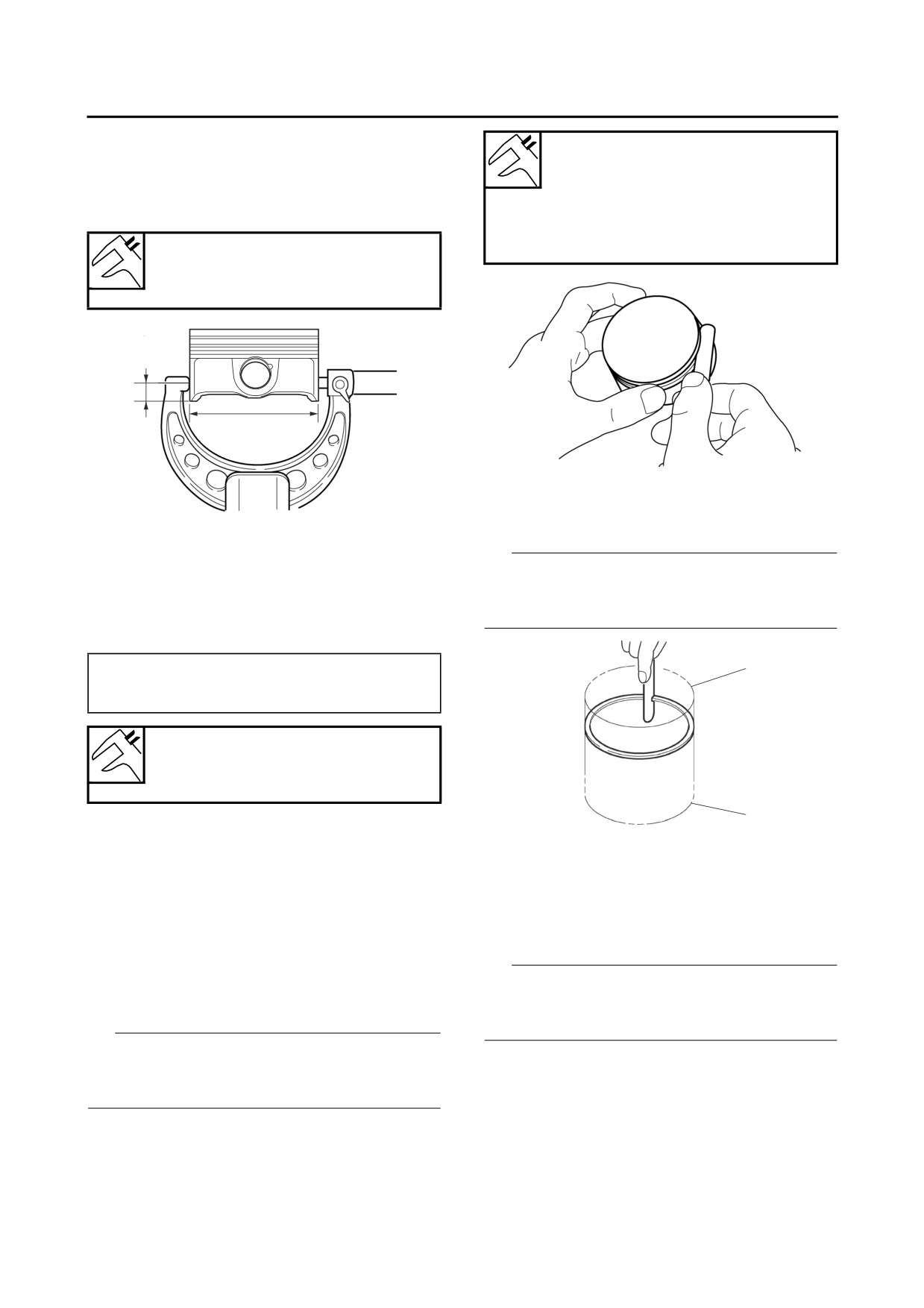
CYLINDER HEAD, CYLINDER, AND PISTON
b. If out of specification, replace the cylinder,
Top ring
and replace the piston and piston rings as a
Ring side clearance limit
set.
0.12 mm (0.0047 in)
c. Measure piston skirt diameter “P” with a mi-
2nd ring
crometer.
Ring side clearance limit
0.12 mm (0.0047 in)
Diameter
102.960-102.975 mm (4.0535-
4.0541 in)
a
P
2. Install:
• Piston ring
(into the cylinder)
a.
11.0 mm (0.43 in) from the bottom edge of the
piston
TIP
Use the piston crown to level the piston ring near
d. If out of specification, replace the piston and
bottom of cylinder “a”, where cylinder wear is
piston rings as a set.
lowest.
e. Calculate the piston-to-cylinder clearance
with the following formula.
• Piston-to-cylinder clearance =
a
Cylinder bore “C” -
Piston skirt diameter “P”
Piston-to-cylinder clearance
0.040-0.075 mm (0.0016-0.0030
in)
b
f. If out of specification, replace the cylinder,
and replace the piston and piston rings as a
b. Upper of cylinder
set.
3. Measure:
▲▲▲▲▲▲▲▲▲▲▲▲▲▲▲▲▲▲▲▲▲▲▲▲▲▲▲▲▲▲▲▲
• Piston ring end gap
EBS30148
Out of specification → Replace the piston
CHECKING THE PISTON RINGS
ring.
1. Measure:
• Piston ring side clearance
TIP
Out of specification → Replace the piston
The oil ring expander end gap cannot be mea-
and piston rings as a set.
sured. If the oil ring rail gap is excessive, replace
TIP
all three piston rings.
Before measuring the piston ring side clearance,
eliminate any carbon deposits from the piston
ring grooves and piston rings.
5-24

-------------------------------------------------------------------------------------------------------------------------------------------------------------

CYLINDER HEAD, CYLINDER, AND PISTON
EBS30150
INSTALLING THE PISTON AND CYLINDER
Top ring
End gap (installed) limit
1. Install:
0.50 mm (0.0197 in)
• Oil ring expander “1”
2nd ring
• Lower oil ring rail “2”
End gap (installed) limit
• Upper oil ring rail “3”
0.70 mm (0.0276 in)
• 2nd ring “4”
Oil ring
• Top ring “5”
End gap (installed) limit
TIP
1.0 mm (0.04 in)
Be sure to install the piston rings so that the
EBS30149
manufacturer’s marks or numbers face up.
CHECKING THE PISTON PIN
1.
Check:
• Piston pin
Blue discoloration/grooves → Replace the
piston pin, and then check the lubrication sys-
tem.
2.
Measure:
• Piston pin outside diameter “a”
1
Out of specification → Replace the piston pin.
2
Piston pin outside diameter limit
22.974 mm (0.9045 in)
2. Install:
• Piston “1”
• Piston pin “2”
• Piston pin clips “3”
New
TIP
• Apply engine oil to the piston pin.
• Make sure the manufacturer’s mark “a” on the
piston points towards the AC magneto side.
• Install the piston pin from the side of the piston
that has the manufacturer’s mark “a”.
• Before installing the piston pin clips, cover the
crankcase opening with a clean rag to prevent
3.
Measure:
the clips from falling into the crankcase.
• Piston pin bore diameter “b”
Out of specification → Replace the piston.
1 a
Piston pin bore inside diameter
limit
23.035 mm (0.9069 in)
3 New
2
3. Install:
• Cylinder gasket
New
• Dowel pins
4. Lubricate:
b
• Piston
• Piston rings
• Cylinder
(with the recommended lubricant)
5-25

-------------------------------------------------------------------------------------------------------------------------------------------------------------

CYLINDER HEAD, CYLINDER, AND PISTON
Recommended lubricant
Engine oil
5. Install:
×4
• Cylinder “1”
FWD
• Timing chain guide (exhaust side)
×4
TIP
• While compressing the piston rings with one
1
hand, install the cylinder with the other hand.
• Pass the timing chain and timing chain guide
4
(exhaust side) through the timing chain cavity.
6
8
1
7
5
2
3
▼▼▼▼▼▼▼▼▼▼▼▼▼▼▼▼▼▼▼▼▼▼▼▼▼▼▼▼▼▼▼▼
a. Temporarily tighten the cylinder head bolts
EBS30440
(M6) and cylinder bolts (M6).
INSTALLING THE CYLINDER HEAD
b. Tighten the cylinder head bolts (M11) to 30
1. Install:
Nm (3.0 m·kgf, 22 ft·lbf) in the proper tighten-
• Cylinder head
ing sequence.
• Cylinder head bolt (M11) (×4)
New
c. Tighten the cylinder head bolts (M11) to 70
• Cylinder head bolt (M6) (×2)
Nm (7.0 m·kgf, 51 ft·lbf) in the proper tighten-
• Cylinder bolt (M6) (×2)
ing sequence.
TIP
d. Loosen the cylinder head bolts (M11) 360°.
• Pass the timing chain through the timing chain
e. Tighten the cylinder head bolts (M11) to 30
cavity.
Nm (3.0 m·kgf, 22 ft·lbf) in the proper tighten-
• Lubricate the cylinder head bolt (M11) threads
ing sequence.
and mating surface with engine oil.
f. Tighten the cylinder head bolts (M11) to the
specified angle 85-90° in the proper tighten-
2. Tighten:
ing sequence.
• Cylinder head bolts (M11) “1”-“4”
g. Tighten the cylinder head bolts (M11) to the
• Cylinder head bolts (M6) “5”, “6”
specified angle 85-90° in the proper tighten-
• Cylinder bolts (M6) “7”, “8”
ing sequence again.
h. Tighten the cylinder head bolts (M6) and cyl-
Cylinder head bolt (M11)
inder bolts (M6) to 10 Nm (1.0 m·kgf, 7.2
1st: 30 Nm (3.0 m·kgf, 22 ft·lbf)
ft·lbf) in the proper tightening sequence.
2nd: 70 Nm (7.0 m·kgf, 51 ft·lbf)
3rd: Loosen 360°
▲▲▲▲▲▲▲▲▲▲▲▲▲▲▲▲▲▲▲▲▲▲▲▲▲▲▲▲▲▲▲▲
4th: 30 Nm (3.0 m·kgf, 22 ft·lbf)
3. Install:
5th: Specified angle 85-90°
• Oil hose (crankcase to cylinder) “1”
6th: Specified angle 85-90°
• Clamps “2”
(again)
• Oil hose joint “3”
Cylinder head bolt (M6)
• Gaskets
New
10 Nm (1.0 m·kgf, 7.2 ft·lbf)
Cylinder bolt (M6)
• Oil hose union bolt (crankcase to cylinder) “4”
10 Nm (1.0 m·kgf, 7.2 ft·lbf)
5-26

-------------------------------------------------------------------------------------------------------------------------------------------------------------

CYLINDER HEAD, CYLINDER, AND PISTON
Oil hose union bolt (crankcase to
cylinder)
18 Nm (1.8 m·kgf, 13 ft·lbf)
TIP
Tighten the clamp screw of each clamp “2” until
6 slots are visible in the area “a” of the clamp as
shown in the illustration.
3
4
2
a
1
5-27

-------------------------------------------------------------------------------------------------------------------------------------------------------------

VALVES AND VALVE SPRINGS
EBS20037
VALVES AND VALVE SPRINGS
Removing the valves and valve springs
1
E
E
2
3
1
4
E
8
New
2
New
8
5
3
4
5
9
New
10
11
New
10
E
11
New
E
E
New
New
9
E
E
New
E
E
7
E
E
6
13 Nm (1.3 mkgf, 9.4 ftIbf)
Order
Job/Parts to remove
Qty
Remarks
Refer to “CYLINDER HEAD, CYLINDER,
Cylinder head
AND PISTON” on page 5-19.
1
Valve lifter
4
2
Valve pad
4
3
Valve cotter
8
4
Valve spring retainer
4
5
Valve spring
4
6
Intake valve
2
7
Exhaust valve
2
8
Valve stem seal (intake)
2
Gray
9
Valve stem seal (exhaust)
2
Light green
10
Valve spring seat
4
11
Valve guide
4
5-28

-------------------------------------------------------------------------------------------------------------------------------------------------------------

VALVES AND VALVE SPRINGS
EBS30141
TIP
REMOVING THE VALVES
Remove the valve cotters by compressing the
The following procedure applies to all of the
valves and related components.
valve spring with the valve spring compressor
“1” and the valve spring compressor attachment
TIP
“2”.
Before removing the internal parts of the cylinder
head (e.g., valves, valve springs, valve seats),
Valve spring compressor
make sure the valves properly seal.
90890-04019
1. Remove:
Valve spring compressor
• Valve lifter “1”
YM-04019
• Valve pad “2”
Valve spring compressor attach-
ment
TIP
90890-01243
Make a note of the position of each valve lifter
Valve spring compressor adapt-
and valve pad so that they can be reinstalled in
er (26 mm)
their original place.
YM-01253-1
2
1
2. Check:
4. Remove:
• Valve sealing
• Valve spring retainer “1”
Leakage at the valve seat → Check the valve
• Valve spring “2”
face, valve seat, and valve seat width.
• Valve “3”
Refer to “CHECKING THE VALVE SEATS”
• Valve stem seal “4”
on page 5-31.
• Valve spring seat “5”
▼▼▼▼▼▼▼▼▼▼▼▼▼▼▼▼▼▼▼▼▼▼▼▼▼▼▼▼▼▼▼▼
a. Pour a clean solvent “a” into the intake and
TIP
exhaust ports.
Identify the position of each part very carefully so
b. Check that the valves properly seal.
that it can be reinstalled in its original place.
TIP
1
There should be no leakage at the valve seat “1”.
4
2
3
5
EBS30142
CHECKING THE VALVES AND VALVE
GUIDES
▲▲▲▲▲▲▲▲▲▲▲▲▲▲▲▲▲▲▲▲▲▲▲▲▲▲▲▲▲▲▲▲
The following procedure applies to all of the
3. Remove:
valves and valve guides.
• Valve cotters
5-29

-------------------------------------------------------------------------------------------------------------------------------------------------------------

VALVES AND VALVE SPRINGS
1. Measure:
• Valve-stem-to-valve-guide clearance
Out of specification → Replace the valve
guide.
• Valve-stem-to-valve-guide clearance =
Valve guide inside diameter “a” -
Valve stem diameter “b”
Valve-stem-to-valve-guide clear-
ance (intake) limit
0.080 mm (0.0032 in)
b. Install the new valve guide with the valve
Valve-stem-to-valve-guide clear-
guide installer “2” and valve guide remover
ance (exhaust) limit
“1”.
0.100 mm (0.0039 in)
c. After installing the valve guide, bore the valve
guide with the valve guide reamer “3” to ob-
tain the proper valve-stem-to-valve-guide
clearance.
3
2. Replace:
• Valve guide
TIP
TIP
To ease valve guide removal and installation,
After replacing the valve guide, reface the valve
and to maintain the correct fit, heat the cylinder
seat.
head to 100 °C (212 °F) in an oven.
▼▼▼▼▼▼▼▼▼▼▼▼▼▼▼▼▼▼▼▼▼▼▼▼▼▼▼▼▼▼▼▼
a. Remove the valve guide with the valve guide
remover “1”.
5-30

-------------------------------------------------------------------------------------------------------------------------------------------------------------

VALVES AND VALVE SPRINGS
1.
Eliminate:
Valve guide remover & installer
• Carbon deposits
set (ø5.5)
(from the valve face and valve seat)
90890-04016
2.
Check:
Valve guide remover (5.5 mm)
• Valve seat
YM-01122
Pitting/wear → Replace the cylinder head.
Valve guide remover & installer
3.
Measure:
set (ø5.5)
• Valve seat width “a”
90890-04016
Valve guide installer (5.5 mm)
Out of specification → Replace the cylinder
YM-04015
head.
Valve guide remover & installer
set (ø5.5)
Valve seat contact width (intake)
90890-04016
1.34-1.48 mm (0.0528-0.0583 in)
Valve guide reamer (5.5 mm)
Valve seat contact width (ex-
YM-01196
haust)
1.34-1.48 mm (0.0528-0.0583 in)
▲▲▲▲▲▲▲▲▲▲▲▲▲▲▲▲▲▲▲▲▲▲▲▲▲▲▲▲▲▲▲▲
3. Eliminate:
• Carbon deposits
(from the valve face and valve seat)
4. Check:
• Valve face
Pitting/wear → Grind the valve face.
• Valve stem end
Mushroom shape or diameter larger than the
body of the valve stem → Replace the valve.
5. Measure:
▼▼▼▼▼▼▼▼▼▼▼▼▼▼▼▼▼▼▼▼▼▼▼▼▼▼▼▼▼▼▼▼
• Valve stem runout
a. Apply blue layout fluid “b” onto the valve face.
Out of specification → Replace the valve.
TIP
• When installing a new valve, always replace
the valve guide.
• If the valve is removed or replaced, always re-
place the valve stem seal.
Valve stem runout
0.040 mm (0.0016 in)
b. Install the valve into the cylinder head.
c. Press the valve through the valve guide and
onto the valve seat to make a clear impres-
sion.
d. Measure the valve seat width.
TIP
Where the valve seat and valve face contacted
one another, the blueing will have been re-
moved.
EBS30143
▲▲▲▲▲▲▲▲▲▲▲▲▲▲▲▲▲▲▲▲▲▲▲▲▲▲▲▲▲▲▲▲
CHECKING THE VALVE SEATS
4. Lap:
The following procedure applies to all of the
• Valve face
valves and valve seats.
• Valve seat
5-31

-------------------------------------------------------------------------------------------------------------------------------------------------------------

VALVES AND VALVE SPRINGS
TIP
After replacing the cylinder head or replacing the
valve and valve guide, the valve seat and valve
face should be lapped.
▼▼▼▼▼▼▼▼▼▼▼▼▼▼▼▼▼▼▼▼▼▼▼▼▼▼▼▼▼▼▼▼
a. Apply a coarse lapping compound “a” to the
valve face.
ECB01360
NOTICE
Do not let the lapping compound enter the
h. Install the valve into the cylinder head.
gap between the valve stem and the valve
i. Press the valve through the valve guide and
guide.
onto the valve seat to make a clear impres-
sion.
j. Measure the valve seat width “c” again. If the
valve seat width is out of specification, reface
and lap the valve seat.
b. Apply engine oil onto the valve stem.
c. Install the valve into the cylinder head.
d. Turn the valve until the valve face and valve
seat are evenly polished, then clean off all of
the lapping compound.
▲▲▲▲▲▲▲▲▲▲▲▲▲▲▲▲▲▲▲▲▲▲▲▲▲▲▲▲▲▲▲▲
TIP
EBS30144
For the best lapping results, lightly tap the valve
CHECKING THE VALVE SPRINGS
seat while rotating the valve back and forth be-
The following procedure applies to all of the
tween your hands.
valve springs.
1. Measure:
• Valve spring tilt “a”
Out of specification → Replace the valve
spring.
Spring tilt (intake)
1.7 mm (0.07 in)
Spring tilt (exhaust)
1.7 mm (0.07 in)
e. Apply a fine lapping compound to the valve
face and repeat the above steps.
f. After every lapping procedure, be sure to
clean off all of the lapping compound from the
valve face and valve seat.
g. Apply blue layout fluid “b” onto the valve face.
5-32

-------------------------------------------------------------------------------------------------------------------------------------------------------------

VALVES AND VALVE SPRINGS
EBS30441
TIP
CHECKING THE VALVE LIFTERS
• Make sure each valve is installed in its original
The following procedure applies to all of the
valve lifters.
place.
• Install the valve springs with the larger pitch “a”
1. Check:
facing up.
• Valve lifter
Damage/scratches → Replace the valve lift-
5
ers and cylinder head.
2 New
EBS30145
INSTALLING THE VALVES
The following procedure applies to all of the
4
valves and related components.
1. Deburr:
3
1
• Valve stem end
(with an oil stone)
2.
Lubricate:
• Valve stem “1”
b. Smaller pitch
• Valve stem end
• Valve stem seal “2”
4. Install:
(with the recommended lubricant)
• Valve cotters
TIP
Recommended lubricant
Install the valve cotters by compressing the
Engine oil
valve spring with the valve spring compressor
“1” and the valve spring compressor attachment
“2”.
2
Valve spring compressor
E
90890-04019
Valve spring compressor
1
YM-04019
Valve spring compressor attach-
E
ment
90890-01243
Valve spring compressor adapt-
3.
Install:
er (26 mm)
• Valve spring seat “1”
YM-01253-1
(into the cylinder head)
• Valve stem seal “2”
New
• Valve “3”
• Valve spring “4”
• Valve spring retainer “5”
5-33

-------------------------------------------------------------------------------------------------------------------------------------------------------------

VALVES AND VALVE SPRINGS
5. To secure the valve cotters onto the valve
stem, lightly tap the valve tip with a soft-face
hammer.
ECB01370
NOTICE
Hitting the valve tip with excessive force
could damage the valve.
6. Lubricate:
• Valve pad
• Valve lifter
(with the recommended lubricant)
Recommended lubricant
Engine oil
7. Install:
• Valve pad
• Valve lifter
TIP
• The valve lifter must move smoothly when ro-
tated with a finger.
• Each valve lifter and valve pad must be rein-
stalled in their original position.
5-34

-------------------------------------------------------------------------------------------------------------------------------------------------------------

AC MAGNETO AND STARTER CLUTCH
EBS20039
AC MAGNETO AND STARTER CLUTCH
Removing the AC magneto and starter clutch
3.0 Nm (0.30 mkgf, 2.2 ftIbf)
18 Nm (1.8 mkgf, 13 ftIbf)
LT
18 Nm (1.8 mkgf, 13 ftIbf)
10 Nm (1.0 mkgf, 7.2 ftIbf)
1
5
New
New
(3)
LT
New
4
E
New
E
E
2
3
(9)
New
10 Nm (1.0 mkgf, 7.2 ftIbf)
New
11 Nm (1.1 mkgf, 8.0 ftIbf)
E
4.0 Nm (0.40 mkgf, 2.9 ftIbf)
(8)
E
E
160 Nm (16 mkgf, 116 ftlbf)
14 Nm (1.4 mkgf, 10 ftIbf)
E
Order
Job/Parts to remove
Qty
Remarks
Drain.
Coolant
Refer to “CHANGING THE COOLANT” on
page 3-29.
Drain.
Engine oil
Refer to “CHANGING THE ENGINE OIL” on
page 3-24.
Refer to “GENERAL CHASSIS (4)” on page
Footrest board (left)
4-11.
Refer to “ENGINE REMOVAL (2)” on page
Drive select lever unit
5-6.
Water pump housing
Refer to “WATER PUMP” on page 6-10.
1
Oil pipe (AC magneto cover)
1
2
Lead holder bracket
1
3
AC magneto cover
1
4
AC magneto cover gasket
1
AC magneto/crankshaft position sensor lead
5
1
holder
5-35

-------------------------------------------------------------------------------------------------------------------------------------------------------------

AC MAGNETO AND STARTER CLUTCH
Removing the AC magneto and starter clutch
3.0 Nm (0.30 mkgf, 2.2 ftIbf)
18 Nm (1.8 mkgf, 13 ftIbf)
LT
18 Nm (1.8 mkgf, 13 ftIbf)
6
10 Nm (1.0 mkgf, 7.2 ftIbf)
New
New
(3)
LT
7
New
E
New
E
E
9
8
13
(9)
11
New
10
10 Nm (1.0 mkgf, 7.2 ftIbf)
15
New
11 Nm (1.1 mkgf, 8.0 ftIbf)
E
4.0 Nm (0.40 mkgf, 2.9 ftIbf)
14
12
(8)
E
E
160 Nm (16 mkgf, 116 ftlbf)
14 Nm (1.4 mkgf, 10 ftIbf)
16
E
Order
Job/Parts to remove
Qty
Remarks
6
Crankshaft position sensor
1
7
Stator coil
1
8
Starter idle gear 1
1
9
Starter idle gear shaft 1
1
10
Starter idle gear 2
1
11
Starter idle gear shaft 2
1
12
AC magneto rotor
1
13
Woodruff key
1
14
Starter wheel gear
1
15
Bushing
1
16
Starter clutch
1
5-36

-------------------------------------------------------------------------------------------------------------------------------------------------------------

AC MAGNETO AND STARTER CLUTCH
EBS30151
• Make sure the flywheel puller is centered over
REMOVING THE AC MAGNETO ROTOR
the AC magneto rotor.
1. Remove:
• AC magneto cover
Flywheel puller (M38 X P1.5)
TIP
90890-04178
Loosen each bolt 1/4 of a turn at a time, in stag-
Flywheel puller (M38 X P1.5)
es and in a crisscross pattern. After all of the
YM-04178
bolts are fully loosened, remove them.
1
2
EBS30152
2. Remove:
REMOVING THE STARTER CLUTCH
• AC magneto rotor nut “1”
1. Remove:
• Washer
• Starter clutch bolts “1”
TIP
TIP
Hold the AC magneto rotor “2” with the rotor
holding tool “3” while loosening the AC magneto
holding tool “3” while removing the starter clutch
rotor nut.
bolts.
Rotor holding tool
Rotor holding tool
90890-04166
90890-04166
YM-04166
YM-04166
1
1
1
3
2
3
1
2
3. Remove:
EBS30153
• AC magneto rotor “1”
CHECKING THE STARTER CLUTCH
(with the starter clutch)
1. Check:
• Woodruff key
• Starter clutch rollers
ECB01390
Damage/wear → Replace.
NOTICE
2. Check:
To protect the end of the crankshaft, place an
• Starter idle gear
appropriate sized socket between the fly-
• Starter wheel gear
wheel puller set center bolt and the crank-
Burrs/chips/roughness/wear → Replace the
shaft.
defective part(s).
TIP
• Use the flywheel puller “2”.
5-37

-------------------------------------------------------------------------------------------------------------------------------------------------------------

AC MAGNETO AND STARTER CLUTCH
3. Check:
Starter clutch bolt
• Starter clutch gear contact surfaces
14 Nm (1.4 m·kgf, 10 ft·lbf)
Damage/pitting/wear → Replace the defec-
tive part(s).
TIP
4. Check:
• Starter clutch operation
While holding the AC magneto rotor “2” with the
▼▼▼▼▼▼▼▼▼▼▼▼▼▼▼▼▼▼▼▼▼▼▼▼▼▼▼▼▼▼▼▼
rotor holding tool “3”, tighten the starter clutch
a. Install the starter clutch and stater wheel gear
bolts.
“1” onto the AC magneto rotor “2”, and hold
the AC magneto rotor.
Rotor holding tool
b. When turning the starter wheel gear clock-
90890-04166
wise “A”, the starter clutch and the starter
YM-04166
wheel gear should engage; otherwise, the
starter clutch is faulty and must be replaced.
1
c. When turning the starter wheel gear counter-
3
clockwise “B”, it should turn freely; otherwise,
the starter clutch is faulty and must be re-
placed.
1
1
A
1
2
EBS30156
INSTALLING THE AC MAGNETO ROTOR
1. Install:
B
• Woodruff key
2
• AC magneto rotor “1”
▲▲▲▲▲▲▲▲▲▲▲▲▲▲▲▲▲▲▲▲▲▲▲▲▲▲▲▲▲▲▲▲
• Washer “2”
• AC magneto rotor nut “3”
EBS30155
INSTALLING THE STARTER CLUTCH
TIP
1. Install:
• Clean the tapered portion of the crankshaft and
• Bushing “1”
the AC magneto rotor hub.
(into the starter wheel gear “2”)
• When installing the AC magneto rotor, make
sure the woodruff key is properly seated in the
Installed depth
keyway of the crankshaft.
0.7 mm (0.03 in)
• Lubricate the threads of the crankshaft and
washer mating surfaces with engine oil.
• Install the washer “2” with its rounded side “a”,
2
facing away from the AC magneto rotor.
• After installing the AC magneto rotor, check
1
that the AC magneto rotor rotates smoothly. If
not, reinstall the woodruff key and AC magneto
rotor.
a
a
a. Installed depth
2. Install:
• Starter clutch
• Starter clutch bolts “1”
5-38

-------------------------------------------------------------------------------------------------------------------------------------------------------------

AC MAGNETO AND STARTER CLUTCH
b
2
a
3
a
2
3
1
1
2. Tighten:
10
• AC magneto rotor nut “1”
4
AC magneto rotor nut
6
8
160 Nm (16 m·kgf, 116 ft·lbf)
1
3
TIP
2
Hold the AC magneto rotor “2” with the rotor
7
holding tool “3” while tightening the AC magneto
5
9
rotor nut.
11
Rotor holding tool
90890-04166
YM-04166
3
1
2
3. Install:
• AC magneto cover “1”
AC magneto cover bolt
10 Nm (1.0 m·kgf, 7.2 ft·lbf)
TIP
• Align the slot “a” in the impeller shaft “2” with
the projection “b” on the oil pump shaft “3”.
• Tighten the AC magneto cover bolts in the
proper tightening sequence as shown.
5-39

-------------------------------------------------------------------------------------------------------------------------------------------------------------

ELECTRIC STARTER
EBS20040
ELECTRIC STARTER
Removing the starter motor
10 Nm (1.0 mkgf, 7.2 ftIbf)
11 Nm (1.1 mkgf, 8.0 ftIbf)
1
2
3
Order
Job/Parts to remove
Qty
Remarks
Refer to “ENGINE REMOVAL (1)” on page
Muffler
5-3.
1
Starter motor lead
1
Disconnect.
2
Engine ground lead
1
Disconnect.
3
Starter motor
1
5-40

-------------------------------------------------------------------------------------------------------------------------------------------------------------

ELECTRIC STARTER
Disassembling the starter motor
11 Nm (1.1 mkgf, 8.0 ftIbf)
New
2
3
New
5
(4)
New
New
New
LS
New
LS
4
1
New
New
5 Nm (0.5 mkgf, 3.6 ftIbf)
Order
Job/Parts to remove
Qty
Remarks
1
Starter motor front cover
1
2
Starter motor rear cover
1
3
Brush set
1
4
Armature assembly
1
5
Starter motor yoke
1
5-41

-------------------------------------------------------------------------------------------------------------------------------------------------------------

ELECTRIC STARTER
EBS30157
CHECKING THE STARTER MOTOR
1. Check:
M
• Commutator
Dirt → Clean with 600-grit sandpaper.
2
2. Measure:
• Mica undercut “a”
1
Out of specification → Cut the mica to the
proper measurement with a hacksaw blade
that has been grounded to fit the commutator.
Mica undercut (depth)
▲▲▲▲▲▲▲▲▲▲▲▲▲▲▲▲▲▲▲▲▲▲▲▲▲▲▲▲▲▲▲▲
0.70 mm (0.03 in)
4. Measure:
• Brush length “a”
TIP
Out of specification → Replace the brush set.
The mica of the commutator must be undercut to
Brush overall length limit
ensure proper operation of the commutator.
6.50 mm (0.26 in)
a
a
3. Measure:
• Armature assembly resistances (commutator
5. Check:
and insulation)
• Gear teeth
Out of specification → Replace the starter
Damage/wear → Replace the gear.
motor.
6. Check:
▼▼▼▼▼▼▼▼▼▼▼▼▼▼▼▼▼▼▼▼▼▼▼▼▼▼▼▼▼▼▼▼
• Bearing
a. Measure the armature assembly resistances
• Oil seal
with the digital circuit tester.
Damage/wear → Replace the defective
part(s).
Digital circuit tester
90890-03174
EBS30158
Model 88 Multimeter with ta-
ASSEMBLING THE STARTER MOTOR
chometer
1. Install:
YU-A1927
• Starter motor yoke “1”
• Starter motor front cover “2”
• Starter motor rear cover “3”
Armature coil
Commutator resistance “1”
Starter motor cover bolt
0.0050-0.0150 Ω at 20 °C (68 °F)
5 Nm (0.5 m·kgf, 3.6 ft·lbf)
Insulation resistance “2”
Above 1 MΩ at 20 °C (68 °F)
TIP
Align the match marks “a” on the starter motor
b. If any resistance is out of specification, re-
yoke with the match marks “b” on the starter mo-
place the starter motor.
tor front and rear covers.
5-42

-------------------------------------------------------------------------------------------------------------------------------------------------------------

ELECTRIC STARTER
b
a
b
2
1
3
5-43


Content      ..     10      11      12      13     ..