Doosan DX255LC. Operation and Maintenance Manual (2006) - page 3
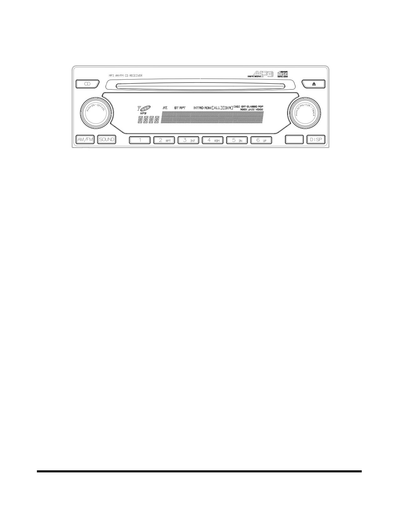
CD Player (Optional)
AST/DIR
FG000109
Figure 123
Operating Controls
OP000482
2-56
MISCELLANEOUS ELECTRICAL
DEVICES
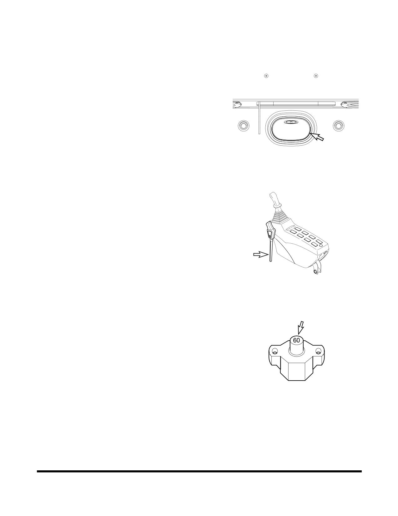
Cabin Light
A light is installed on the top of the operator's compartment.
The light will work despite starter switch position.
NOTE:
If light is left "ON" for a long time while the engine is
not running, the battery will be discharged.
FG000417
Figure 124
Pilot Cutoff Switch
When the safety lever is put into the "LOCK" position, the
switch deactivates the work and travel levers. With the work
and travel levers deactivated, no digging/operational work
can be done.
FG000211
Figure 125
Circuit Breaker
A main circuit breaker is in the battery box. It will
automatically cut off in case of an electrical short circuit or
overload. This will prevent the electric wiring and
components from being burned or damaged.
If the circuit breaker is cut off, check all related circuits, this
means something is wrong in the electric circuit.
After maintenance, press the red button for normal operation
of circuit breaker.
HAAE2110
Figure 126
OP000482
Operating Controls
2-57
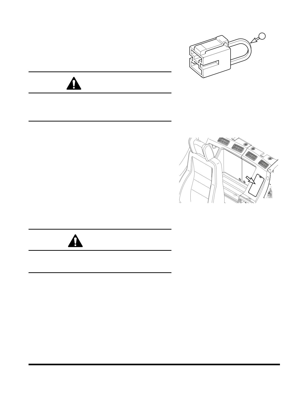
Fusible Link
A fusible link is in the battery box.
A
If the engine does not crank, first check that the starter
switch is turned "ON" and that no power is available (No
indicator lights will light.). Check that the "A" portion (Figure
127) of the fusible link is not broken or burned through.
Replace the fusible link if damage and investigate cause.
HAAE2120
WARNING!
Figure 127
When changing the fusible link, replace the fusible link
with the same capacity part. Otherwise, a fire could
break out in the wiring harness and/or other components
of the circuit. Always use original DOOSAN parts.
Fuse Boxes
There are two fuse boxes (Figure 128) on the left side of
the heater box. The fuses prevent electrical devices from
overloading or shorting.
A decal attached to the inside of the fuse box access cover
indicates the function and amperage of each fuse.
NOTE:
For a further explanation see “Fuse Boxes” on
page 4-73.
Spare fuses are mounted on the inside of fuse box access
FG000110
cover.
Figure 128
Change a fuse if the element separates. If the element of a
new fuse separates, check the circuit and repair the circuit.
CAUTION!
Always replace fuses with the same type and capacity
fuse that was removed. Otherwise, electrical damage
could result.
Operating Controls
OP000482
2-58
SEAT ADJUSTMENT
WARNING!
Adjust the seat position before starting operations or
after changing the operator.
Always fasten your seat belt while operating machine.
Adjust the seat so that the control levers and pedals
can be operated freely and easily with the operator back
against the backrest.
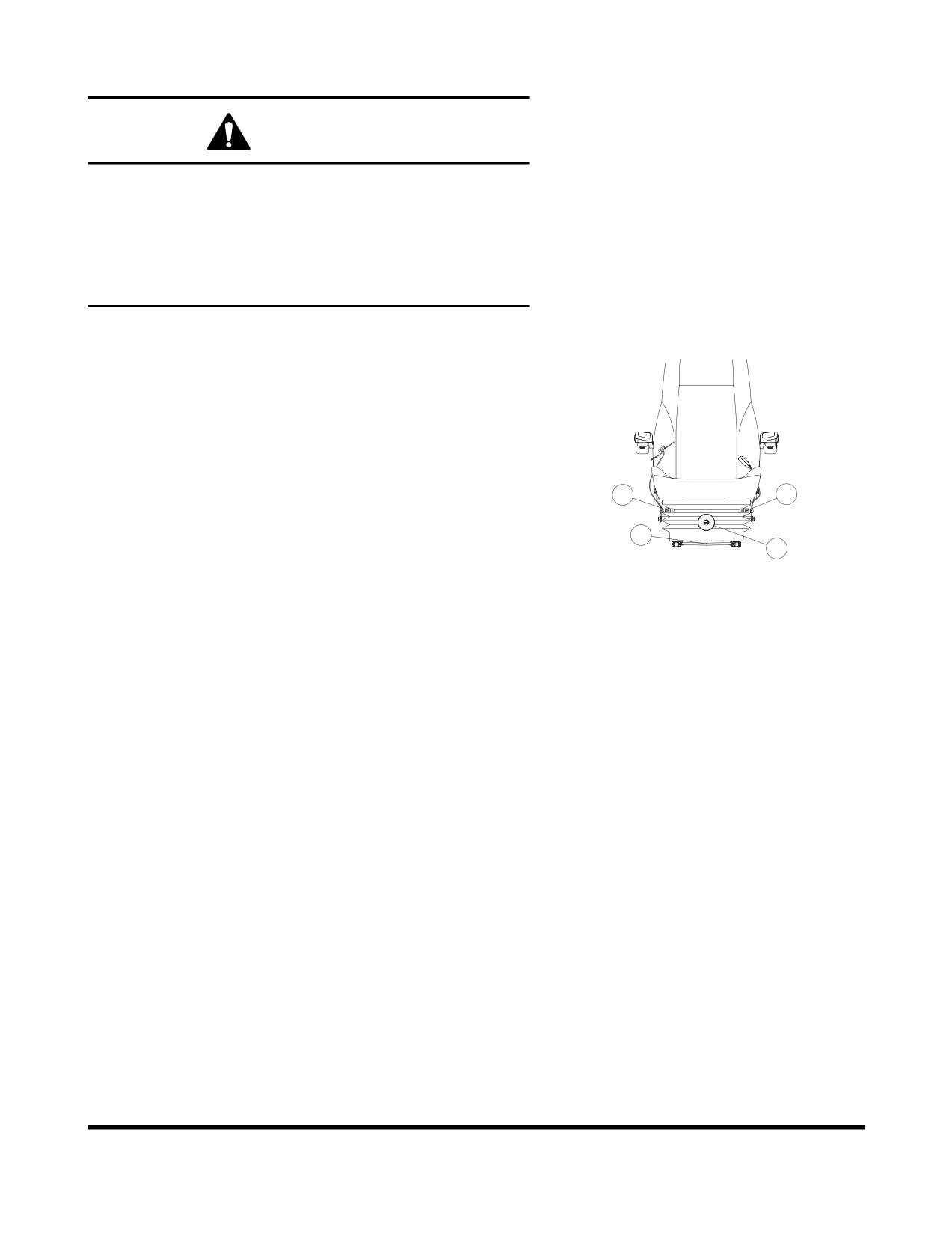
1. Forward / Backward Adjustment
Holding lever (1, Figure
129), raise it up, move the
seat to the desired position. Release lever to lock the
seat in the selected position. Adjustment range is
200 mm (7.9 in).
4
2
2. Seat Tilt and Height Adjustment
1
3
FG000183
Forward Tilt
Figure 129
Push lever (2, Figure 129) down to adjust the angle of
the front of the seat. There are four positions that it
can be set at.
Rear Tilt
Pull lever (2, Figure 129) up to adjust the angle of the
rear of the seat. There are four positions that it can be
set at.
Seat Height
It is possible to move the seat up or down by
combining adjustments forward and rear tilt. Adjust the
seat according to operator's size and work conditions.
Height adjustment is 60 mm (2.4 in).
3. Suspension Adjustment
Turning knob
(3, Figure
129) to right makes the
suspension harder. Turning knob to left makes the
suspension softer. Adjust according to operator's weight
by checking the weight indicator dial. Adjustment range
is from 50 - 120 kg (110 - 265 lb).
OP000482
Operating Controls
2-59
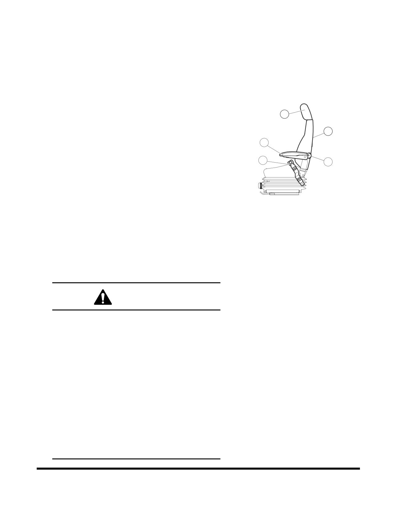
4. Reclining Position Adjustment
Pulling up the right lever (4,Figure 129) allows the seat
backrest to be moved forward or backward.
Sit with your back against the seat back when
adjusting it. If your back is not touching the seat back,
the seat back may suddenly move forward.
5. Armrest Angle Adjustment
The angle of each armrest can be adjusted by turning
7
a dial
(5, Figure
130) on bottom of armrest. When
adjusting the angle, manually raise the armrest before
9
turning the dial.
5
8
6
6. Lumbar Support Adjustment
A lumbar support is located in the seat back.
Turn the dial
(6, Figure
130) counterclockwise to
FG000778
increase the force of the lumbar support
Figure 130
7. Headrest
The headrest (7, Figure 130) can be adjusted forward/
backward and up/down. Move it by holding both sides.
8. Seat Belt
WARNING!
The seat belt is for the operator's safety and
should always be worn. Before driving the machine,
adjust the seat to the desired position for maximum
comfort and machine control, then fasten the seat
belt. Seat belts must be worn across the pelvic
region and adjusted snugly to lessen the chance
and severity of injury in case of an accident. Never
fasten a seat belt across the abdomen.
Under no circumstances should the operator be
standing in the cabin when operating the excavator.
Do not adjust the seat position while the vehicle is
moving because a loss of control may result. Stop
the machine, apply the parking brake, and then
adjust the seat.
Always, check the condition of seat belt and belt
bracket before fastening it. Do not use it with twists
in it. Replace belt or bracket if damaged or worn.
Operating Controls
OP000482
2-60
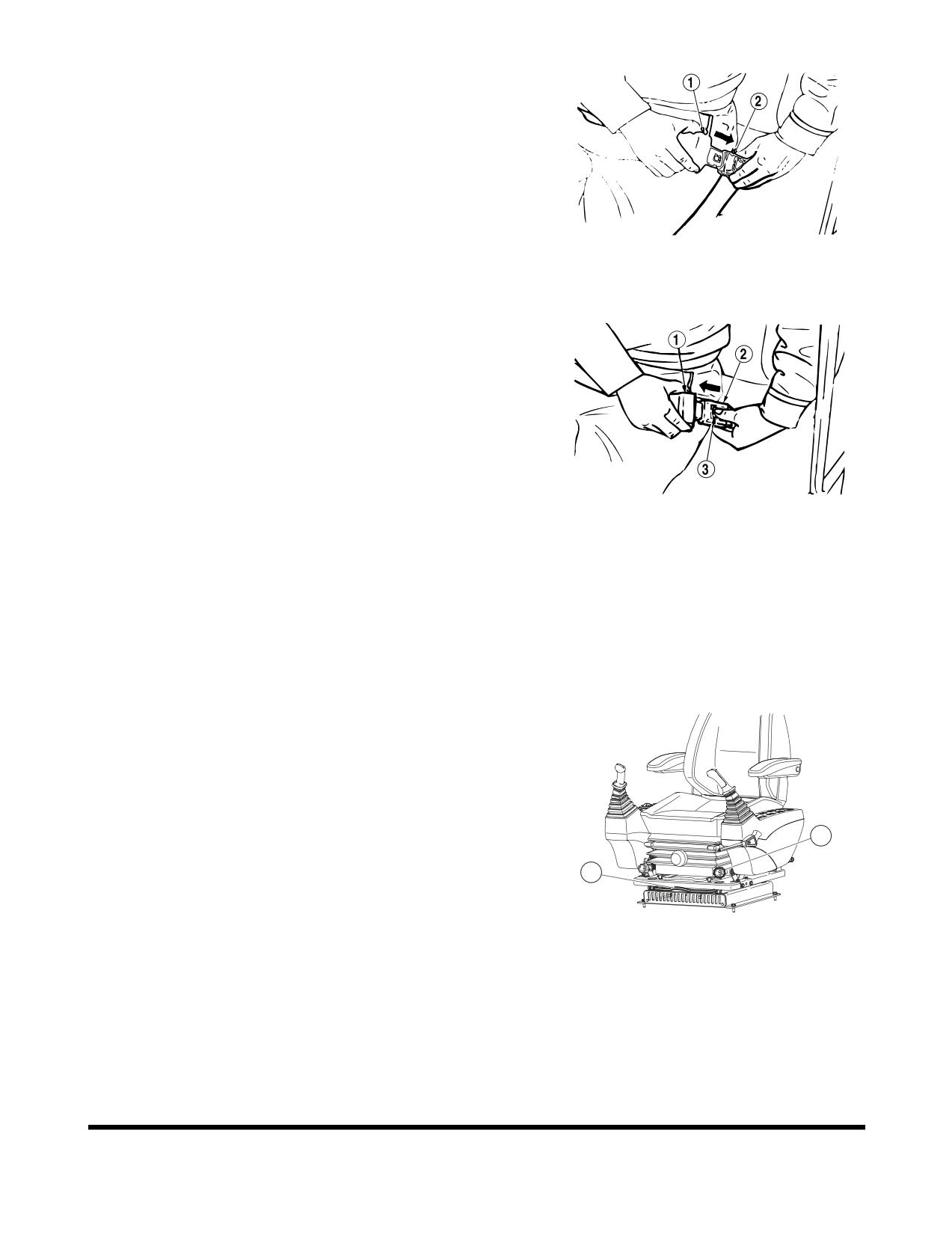
Seat Belt Locking and Unlocking
Insert belt end (1, Figure 131) into the buckle (2). Pull
the belt to check that belt end is locked into buckle.
Adjust belt length so that it comfortably tight against
the operator's pelvic region (hipbone).
HAOB140L
Figure 131
Press the button (3, Figure 132) in the center of buckle
(2) and pull out belt (1) to unlock.
HAOB150L
Figure 132
9. Seat Back-pocket
The seat has a seat back pocket. It is used for storing
the operation and maintenance manual.
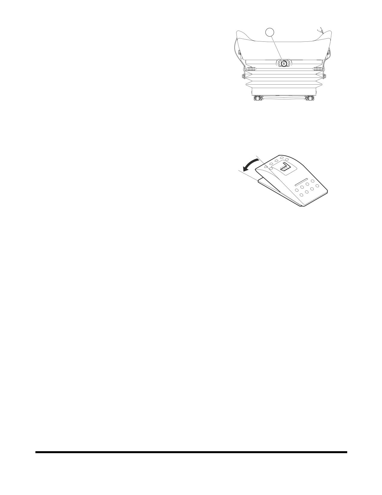
10. Left and Right Control Stand
Adjustment
For operator's convenience, the right and left control
stands and seat can slide together, within a 160 mm
(6.3 in) forward or backward travel distance.
11
Holding lever (10, Figure 133), raise it up, set the seat
to desired position. Release lever to lock the seat in
10
the selected position.
FG000185
Figure 133
11. Left and Right Control Stand Height
Adjustment
The left and right dials (11, Figure 133) at the lower
part of the seat can be turned to adjust the elevation
height of each control stand.
It can be used to adjust the height of the control
joystick.
OP000482
Operating Controls
2-61
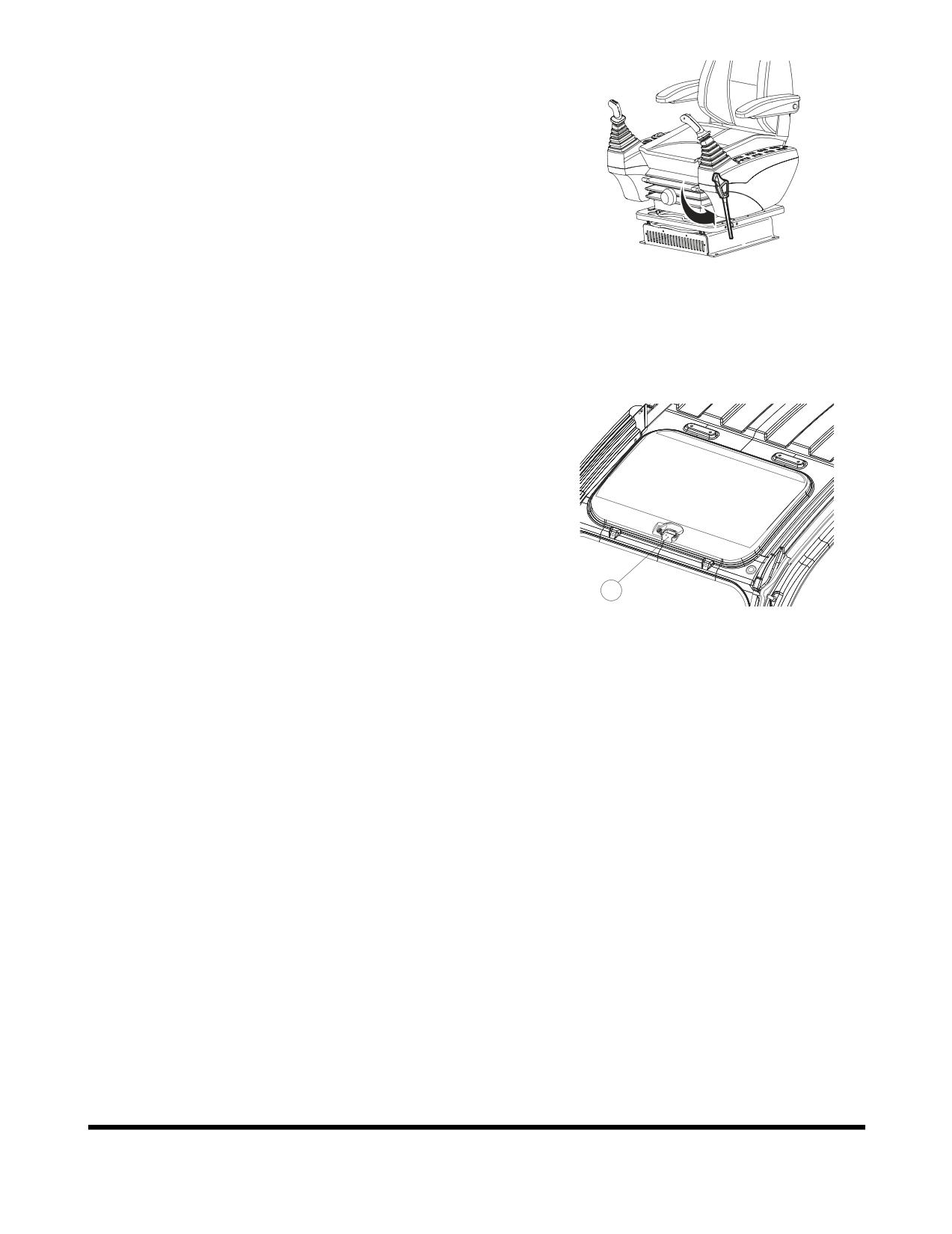
12. Air Suspension Seat (Optional)
12
The operator seat is also available with air suspension
for even better comfort. The switch (12, Figure 134) in
the middle of the seat can be used to adjust the air
cushion. If the switch is pressed, the seat become
harder, and pulling it out makes the seat softer, when
the air is bleed out.
FG000187
Figure 134
13. Heating the Operator's Seat
(Optional)
O
The air suspension seat can be heated. The switch on
I
the left control stand is used to warm the seat. When
heating is not needed or seat is warmed, turn the
switch to "OFF" position.
FG000034
Figure 135
Operating Controls
OP000482
2-62
CEILING COVER
NOTE:
If the machine is equipped with the optional
transparent ceiling cover never use any chemical
cleaners on its surface. Only use warm water to wash
dust and dirt from its surfaces, and after that, dry it
with a soft fabric towel.
Opening the Ceiling Cover
FG000189
1.
Lower bucket to ground.
Figure 136
2.
Set safety lever (Figure 136) on "LOCK."
3.
Pull the lock (1, Figure 137) in front center of ceiling
cover and push it up with handle.
Closing the Ceiling Cover
1.
Lower bucket to ground.
2.
Set safety lever (Figure 136) on "LOCK."
3.
Pull down cover with the handle (Figure 137) so that
the lock (1) can be locked in the bracket in the ceiling
frame.
1
FG000190
Figure 137
OP000482
Operating Controls
2-63
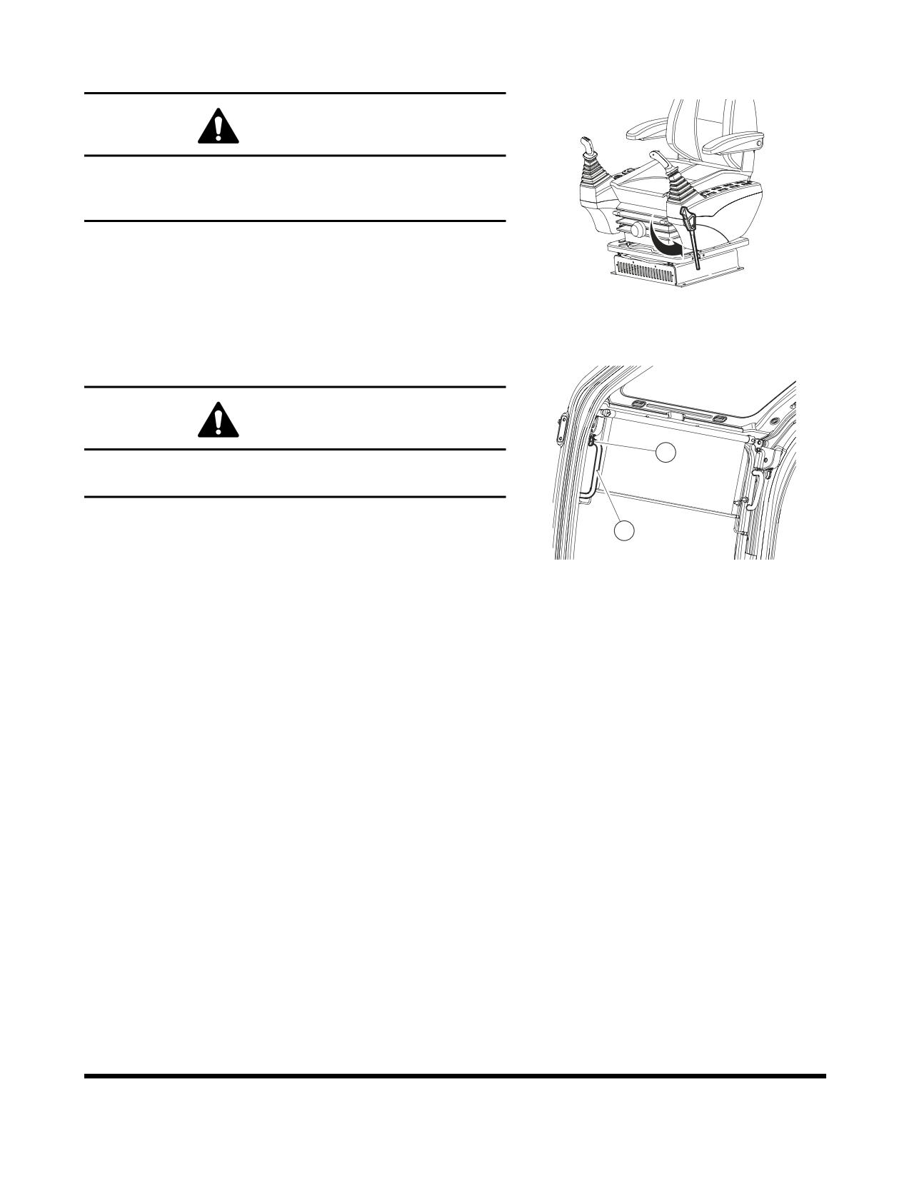
FRONT WINDOWS
WARNING!
When leaving operator's seat, set the safety lever to
"LOCK" position (Figure 138), if not a serious accident
could occur by accidentally moving the work levers.
Front Upper Window
FG000189
The front upper window can be housed in the cabin's
Figure 138
ceiling.
Opening the Window
WARNING!
2
When stowing front window in the cabin roof, make
sure both release levers (1, Figure 139) are latched.
1.
Lower bucket to ground.
1
2.
Set safety lever (Figure 138) on "LOCK."
FG000192
3.
Set engine speed control dial to "LOW IDLE." Allow
Figure 139
engine to idle for three - five minutes.
4.
Shut down engine by turning key to "O" (OFF) position.
5.
Hold the window handles (1, Figure 139), then pull the
lock levers (2) to release the lock. The top of the front
window will come out.
6.
Pull window up, and push it against lock pin at the
rear of the cabin. Make sure that it is securely latched.
7.
Check that lock levers are securely latched in the lock
position.
NOTE:
When the front upper window is open, never
extend your head or body through the window
frame.
NOTE:
If the window happens to fall with a strong
impact against the machine, while some part of
your body is extended out of the cabin, it may
result in bodily injury.
Operating Controls
OP000482
2-64
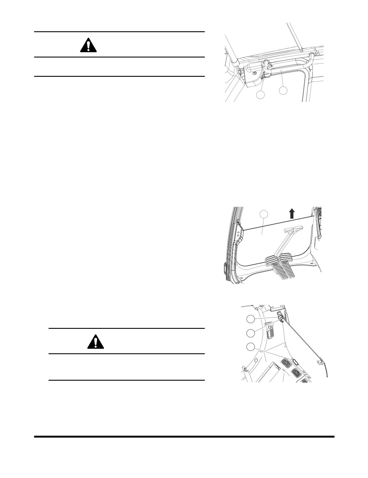
Closing the Window
WARNING!
Be careful that your hands are not caught in window
frame.
1.
Lower bucket to ground.
1
2
2.
Set safety lever (Figure
138) on "LOCK," and shut
FG000193
down engine.
Figure 140
3.
Holding upper handles (1, Figure 140) of front window
with left and right-hand, pull lock levers (2, Figure 140)
to release the lock.
4.
Push window forward, and lower it slowly.
5.
When the bottom of the window, reaches the top of the
front bottom window, push the front window to engage
the lock (2, Figure 139).
6.
Check that lock levers are securely latched in the lock
position.
Front Bottom Window
1
The front bottom window can be removed and stored in the
rear of the cabin.
1.
After stowing the front upper window in the cabin
ceiling, remove bottom window
(1, Figure
141) from
cabin in direction of the arrow.
FG000194
Figure 141
2.
Set bottom window in rubber holders (2, Figure
142)
behind operator's seat. Secure window with left and
right knobs (3) with push button (4).
3
4
WARNING!
2
Never have wet hands when handling a window.
Never drop window or let it come into contact with
other parts of the machine.
FG001345
Figure 142
OP000482
Operating Controls
2-65
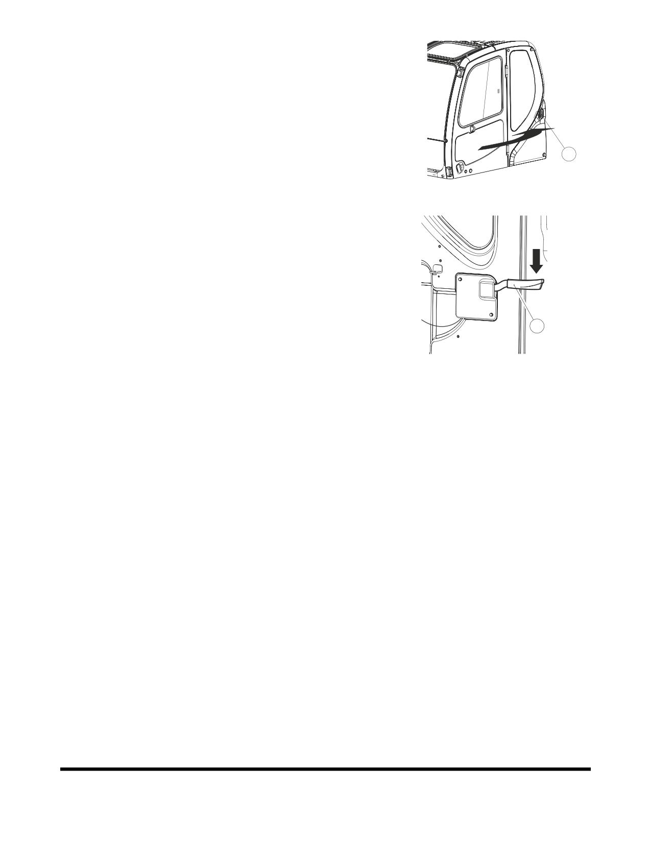
DOOR SIDE LATCH
1.
The door side latch (1, Figure 143) is used to secured
the door to the side of the cabin when it is opened.
NOTE:
Keep the door closed and locked when machine
is not in use.
1
FG000196
Figure 143
2.
To release door from side of cabin, push the latch
lever (2, Figure 144) down. The latch lever is to the
left of the operator's seat.
2
FG000673
Figure 144
Operating Controls
OP000482
2-66
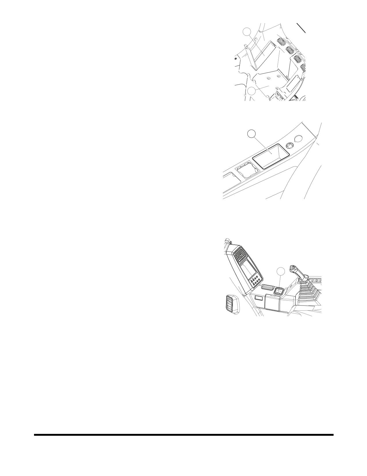
CABIN STORAGE
2
COMPARTMENTS
There are two storage compartments behind the operator's
seat.
The large compartment
(1, Figure
145) is for storing
nonperishable items.
The covered other one (2, Figure 145) is interconnected with
1
the air conditioner. So, it can be supplied with either warm
FG000209
or cool air when air conditioner is turned "ON."
Figure 145
There is a separate small tray (3, Figure 146) on the right
side of operator's seat.
3
FG000675
Figure 146
ASHTRAY
An ashtray
(1, Figure
147) is to the right side of the
operator's seat on the side of the cabin. Always close
ashtray after putting out a cigarette.
1
FG000200
Figure 147
OP000482
Operating Controls
2-67
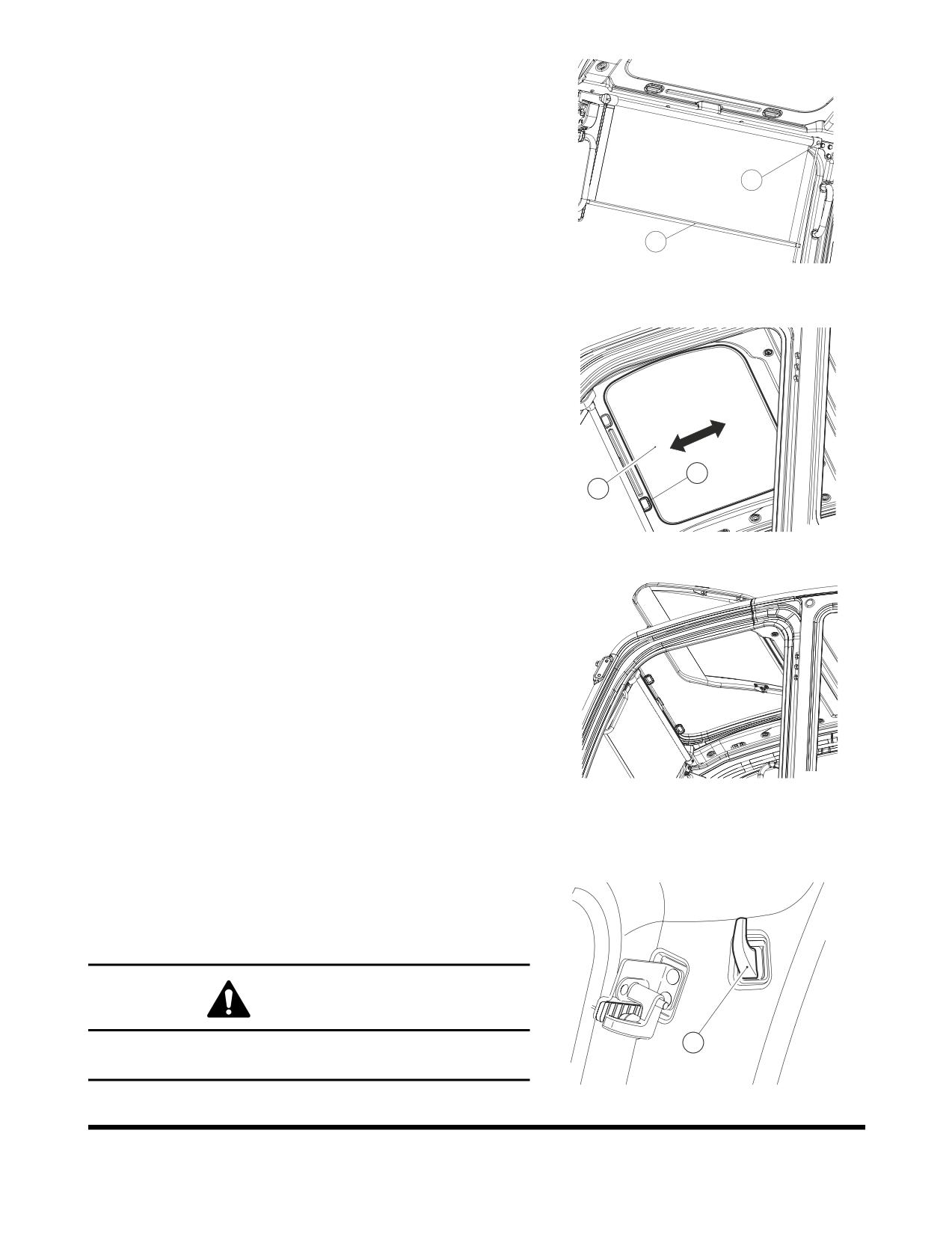
SUN VISOR
The sun visor can be used to reduce the amount of sunlight
coming through the front window and ceiling.
When wanting to reduce the amount of sunlight coming in
the front window, pull bar (1, Figure 148) down.
2
When not wanting protection, hold the bar with left-hand and
push the release button (2, Figure 148) with right-hand. This
will allow the visor to retract.
1
F
G0
00201
NOTE:
Do not allow the visor to roll back up without holding
Figure 148
it. Not holding it may result in damage to the visor and
retract mechanism.
Ceiling sun visor
(3, Figure
149) slides forward and
backwards.Move it with handle (4) on each side.
4
3
FG000676
Figure 149
When opening the ceiling cover (if equipped), push the sun
visor into its compartment (Figure 150).
FG000204
Figure 150
HANGER
A hanger (1, Figure 151) is located on the upper left side of
the operator's compartment.
WARNING!
1
Do not hang anything that will easily fall down, or will
impair your view out of the cabin.
FG000210
Figure 151
Operating Controls
OP000482
2-68
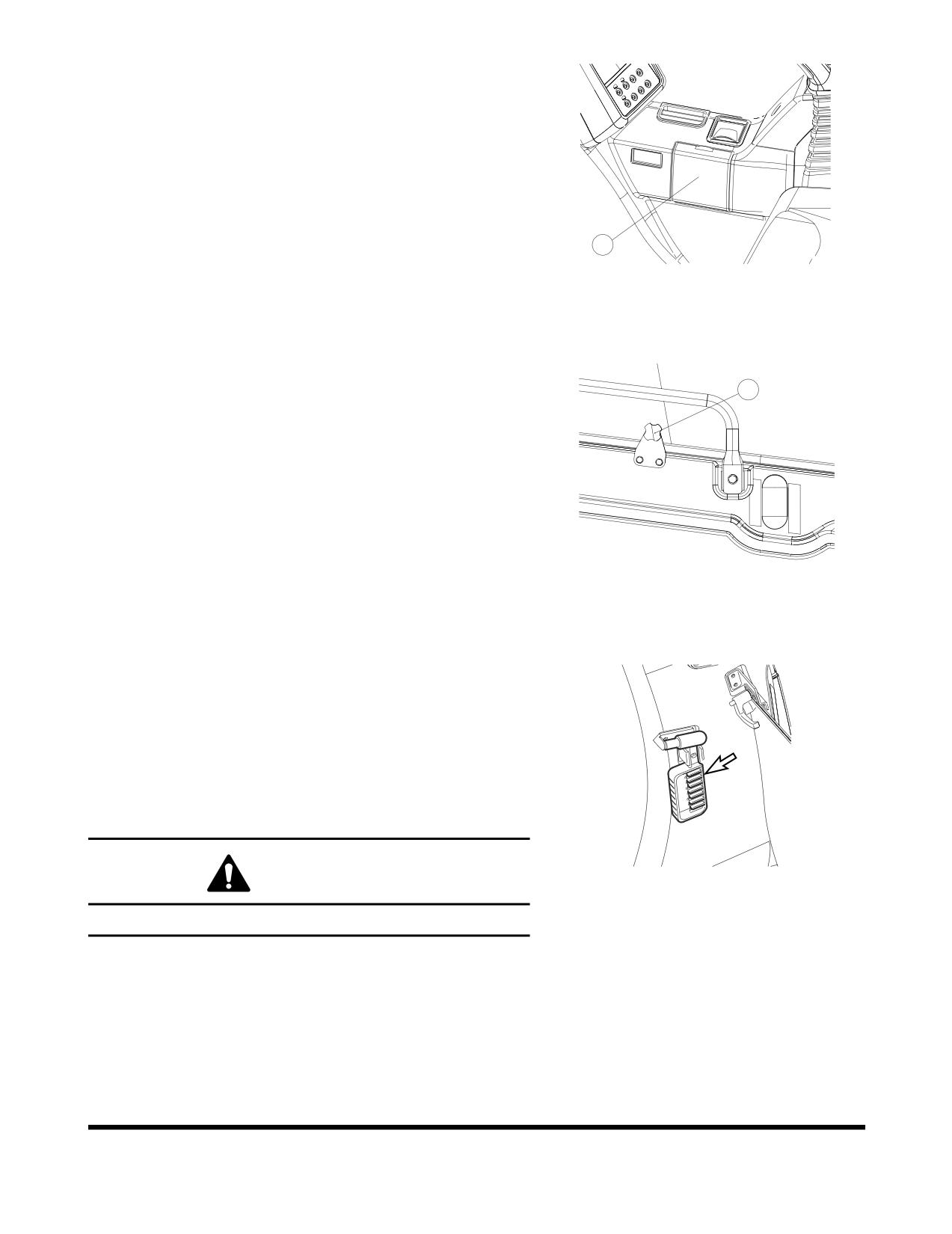
CUP HOLDER
There is a cup holder on the right side of the compartment
(1, Figure 152). Open the access cover and lower it to a
horizontal position.
1
FG000205
Figure 152
DOOR WINDOW HOLDER
1
When the machine is being operated with the cabin door
window opened, window vibration can be reduced by
tightening knob (1, Figure 153) against the window.
FG000206
Figure 153
EMERGENCY GLASS
BREAKING TOOL
The excavator is equipped with a glass breaking tool. It is to
the upper right corner of the cabin. This tool can be used in
case of an emergency situation which requires the breaking
of glass to exit from the cabin. Grip the handle firmly and
use the sharp point to break the glass.
FG000178
WARNING!
Figure 154
Protect your eyes when breaking the glass.
OP000482
Operating Controls
2-69
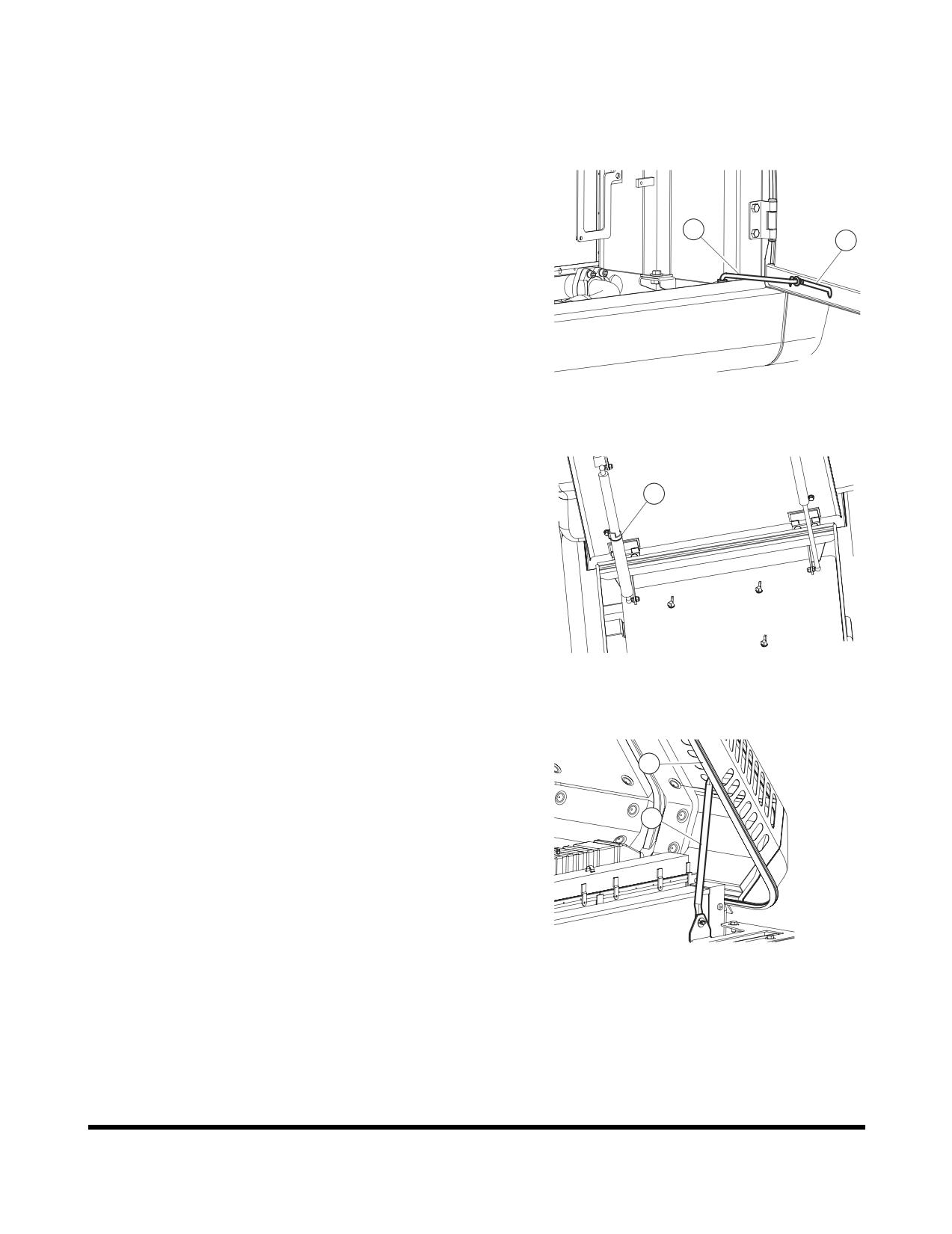
MISCELLANEOUS ACCESS
COVERS AND DOORS
Side Door
Open the side access door and slide prop rod (1, Figure
155) in slot (2) until it locks at the end of slot.
1
2
FG000165
Figure 155
Battery Box Door
1
Opening
Open door until locking device (1, Figure 156) latches.
Closing
While holding door, press locking device to release lock and
close door.
FG000166
Figure 156
Engine Cover
2
Open the cover and slide prop rod (1, Figure 157) in the
slot (2) until it locks in notch at the end of slot to support
the cover.
1
To close cover, move end of prop rod out of notch so it can
slide in slot.
FG000167
Figure 157
Operating Controls
OP000482
2-70
OP000483
3Operation
TO HANDLE A NEW
EXCAVATOR
All DOOSAN Daewoo excavators are inspected and adjusted
before leaving the factory. However, it is required that the
operator follow these steps during the initial break-in period.
Failure to follow these steps may result in damage to the
equipment or reduced performance.
Hour
Load
For first 50 hours of opera-
Maintain about 80% load of
tion.
full capacity (Engine rpm:
80% of rated rpm)
After first 50 hours of opera-
Full load
tion.
If machine is used at full load before it is broken in, it may affect
the life cycle and safe running operations. This could lead to
problems later.
NOTE:
1.
Check daily for leakage of coolant, fuel, engine
oil and hydraulic oil.
2.
Inspect all lubricants daily, add appropriate
lubricants as required.
3.
During operation, monitor all instruments and
gauges from time to time.
4.
Avoid an extreme engine load.
5.
Operate unit at 80% load until engine and all
other components are at operating temperature.
6.
Check that work equipment is operating
normally during operation.
7.
Check machine for loose parts or for damage
that may have occurred during shipping.
8.
Check for loose wiring or terminals, check
gauge operation and battery electrolyte level.
OP000483
Operation
3-1
Lubrication and Filters
1.
Change engine oil and replace oil filter after first 50 hours
of operation.
2.
Change swing reduction device oil after first 250 hours of
operation.
3.
Change hydraulic oil return filter after first 250 hours of
operation.
4.
Replace travel and reduction gear oil after first 250 hours
of operation.
NOTE:
For the replenishment of oil or grease, refer to
“Inspection, Maintenance and Adjustment” on
page 4-1 of this manual.
STARTING AND STOPPING THE
ENGINE
Inspection Before Starting Engine
WARNING!
If a flammable materials such as leaves, paper, etc. are
allowed to accumulate on high temperature components,
such as the engine muffler and turbo, a fire may occur. Fuel,
lubricant and hydraulic oil leaks, may cause a fire. If there is
anything wrong, perform the appropriate corrective action.
Before starting engine, inspect the following items;
1.
Electric system - Check for damaged electric cables, and
loose or missing connectors.
2.
Fuel system - Drain water and sediment from fuel tank and
water separator.
3.
Hydraulic system - Check for hydraulic oil leaks, damaged
tubing and hoses, and interference points of components.
4.
Lubrication - Perform all daily and periodic maintenance
services. Perform services according to reading shown on
hour meter.
5.
Safety - Perform a machine walk-around. Make sure that
no one is under the machine or performing any
maintenance on it, before starting engine.
6.
After starting machine - Check that all operational controls
and components, are in proper operating condition, and
are functioning correctly. Stop operation and correct any
malfunction before continuing work.
Operation
OP000483
3-2
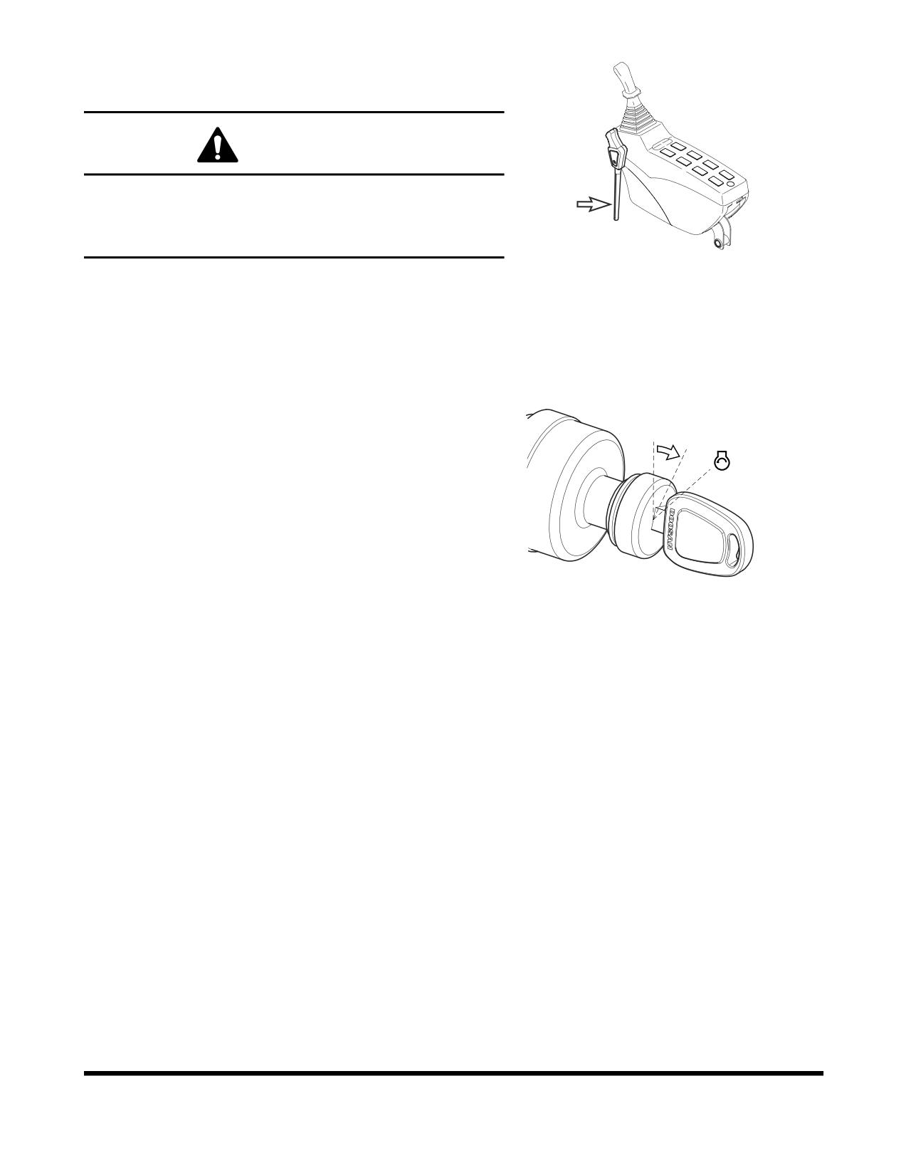
Operational Checks Before Starting
Engine
WARNING!
When leaving operator's seat, set the safety lever to
"LOCK" (Figure
1) position, if not a serious accident
could occur by accidentally moving the travel or work
levers.
FG000211
Figure 1
1.
Set safety lever on "LOCK" (Figure 1).
2.
Fasten seat belt. Check for proper operation and condition.
3.
Set all operation levers in "NEUTRAL."
NOTE:
Be careful not to touch any switches when
starting engine.
4.
Rotate the starter switch to the "I" (ON) position
(Figure 2). Check all indicator lights. A warning buzzer
will sound for about two seconds. After two seconds,
O I
all lights except the following will turn "OFF."
•
Charging warning light
•
Engine oil pressure warning light
•
Engine coolant temperature gauge
•
Fuel gauge
•
Hydraulic oil temperature gauge
FG000084
Figure 2
•
Engine rpm (0 rpm) digital readout
NOTE:
If all of the indicator lights do not come "ON"
when the key is first turned, there is a problem.
OP000483
Operation
3-3
Engine Start
WARNING!
Start the engine after sounding horn and making sure that
there are no people or obstacles in the area.
1.
Perform all steps in “Operational Checks Before
Starting Engine” on page 3-3.
2.
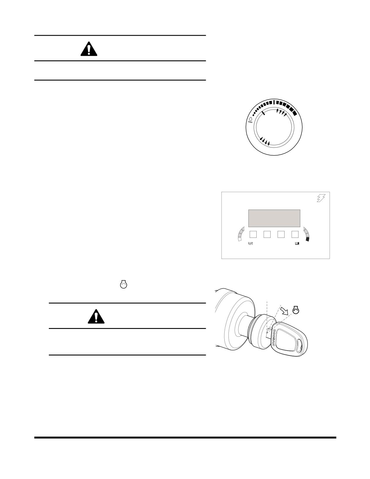
Set engine speed control dial slightly above "LOW
IDLE" (Figure 3).
3.
Sound horn.
HAOB34L
Figure 3
4.
Enter password.
NOTE:
If the security system is "LOCKED," a four-digit
02/05 [MO]
11:30
password will be required to start the engine. If the
system is "UNLOCKED," no password will be
ENTER
required and this display screen will not appear.
PASSWORD
C
H
E/G SPEED
0 RPM
FG001445
Figure 4
" "
5.
Turn starter switch to
(START) position (Figure
5). Engine should start in approximately five seconds.
O I
WARNING!
If the engine does not start after approximately fifteen
seconds of cranking, release the starter switch. Wait
about five minutes and repeat above step.
FG000085
6.
After engine has started, release key. Key will return to the
"I" (ON) position (Figure 5).
Figure 5
7.
Follow procedures in “Hydraulic System Warm-up” on
page 3-9.
Operation
OP000483
3-4
8.
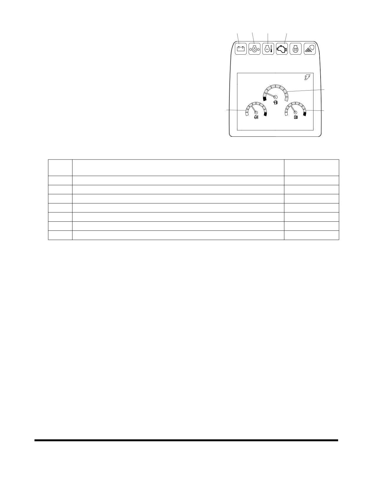
After warming unit, check all operating indicators to make
sure that all engine systems (oil pressure, coolant, etc.) are
4
5
6
7
in the normal operating range. If any problems are noticed,
shut down engine. Normal indicators are:
CHECK
02/05 [MO] 11:30
2
1
3
E/G SPEED
1700 RPM
FG000092
Figure 6
INDICATOR
No.
INSTRUMENT PANEL LIGHT OR GAUGE
READING
1
Engine Coolant Temperature Gauge
Blue Range
2
Fuel Gauge
Blue Range
3
Hydraulic Oil Temperature Gauge
Blue Range
4
Charging Warning Light
OFF
5
Engine Oil Pressure Warning Light
OFF
6
Engine Coolant Temperature Warning Light
OFF
7
Engine Check Warning Light
OFF
9.
Check color of exhaust smoke.
•
No color or light blue - Engine is running in good
condition.
•
Black - Incomplete combustion. Check cause.
•
White or dark blue - Engine is burning engine oil.
Check cause.
10.
Check for usual engine vibration and noises. If any are
heard or felt, investigate cause.
NOTE:
If engine coolant temperature gauge pointer
moves into the red zone, the engine coolant
temperature warning light will turn "ON," a
warning buzzer will sound, and the engine
speed will be automatically reduced. Allow the
engine to run at low idle speed until the
temperature gauge registers in the blue zone
again. When the blue zone is reached, allow the
engine to idle for an additional three - five
minutes before shutting down the engine. If not
allowed to idle, heat surge may develop which
will damage the engine. Allowing the engine to
idle will dissipate heat. Check the coolant level,
look for a loose fan belt, inspect for debris
around radiator, and so on.
OP000483
Operation
3-5
Cold Weather Starting
WARNING!
DO NOT USE STARTING FLUIDS. The preheat system could
cause the starting fluid to explode. Starting fluids should
never be used.
1.
Perform all steps in "Operational Checks Before Starting
Engine."
2.
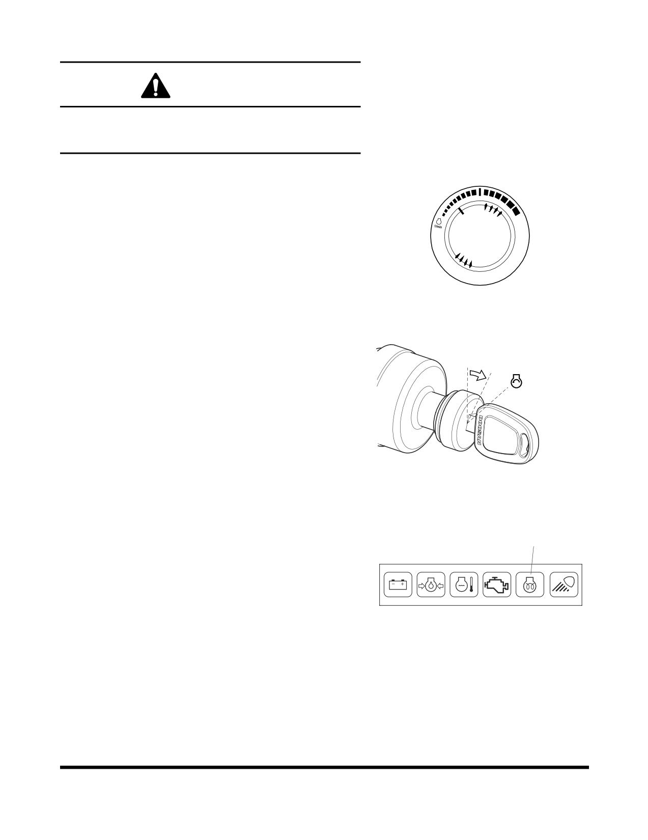
Set engine speed control dial slightly above "LOW
IDLE" (Figure 7).
3.
Sound horn.
HAOB34L
Figure 7
4.
Turn starter switch to the "I" (ON) position (Figure
8).
When preheat cycle is completed, the preheat indicator
light
(1, Figure 9) will turn "OFF."
O I
FG000084
Figure 8
1
CHECK
FG000217
Figure 9
Operation
OP000483
3-6
5.
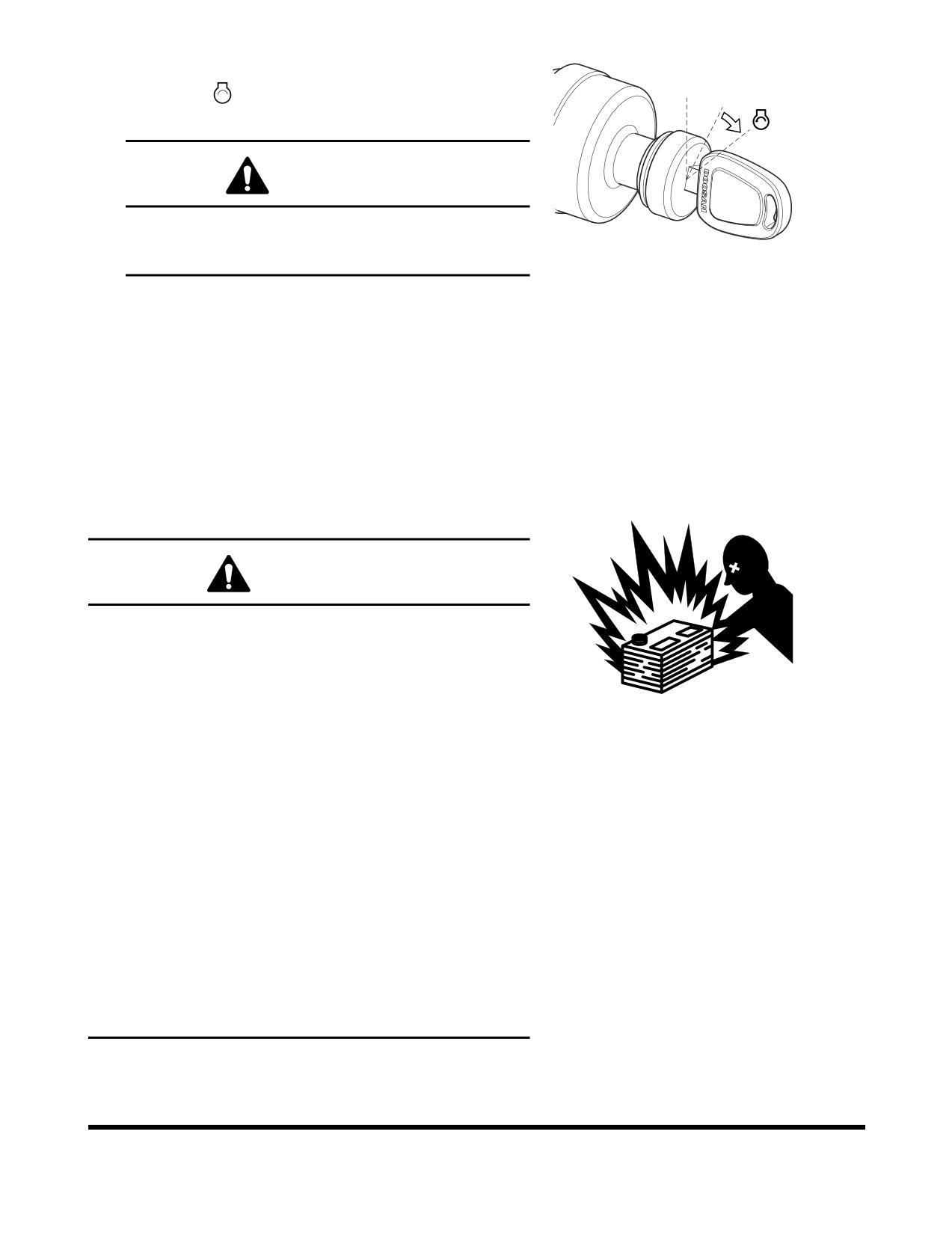
After the preheat completion, immediately turn starter
" "
switch to
(START) position (Figure 10). Engine
O I
should start in approximately five seconds.
WARNING!
If the engine does not start after approximately fifteen
seconds of cranking, release the starter switch. Wait
FG000085
about five minutes and repeat above step.
Figure 10
6.
After engine has started, release key. Key will return to
the "I" (ON) position (Figure 10).
7.
After the engine starts, check all operating indicators to
make sure that all engine systems (oil pressure,
coolant, etc.) are in the normal operating range. If any
problems are noticed, shut down engine.
8.
Follow "Hydraulic System Warm-up" procedures in this
section. (See page 3-9)
Starting Engine With a Booster Cable
WARNING!
1.
An explosive gas is produced while batteries are in
use or being charged. Keep flames or sparks away
from the battery area.
2.
Charge batteries in a well ventilated area.
HAOA440L
3.
Always wear eye protection when starting a machine
Figure 11
with jumper cables.
4.
Improper jump starting procedures can cause an
explosion resulting in personal injury.
5.
Jump start vehicles on dry ground or concrete. Do not
jump start the machine on a steel floor, because the
floor is always grounded.
6.
When starting from another machine, make sure the
machines do not touch.
7.
Always connect the auxiliary battery positive
(+)
terminal too depleted battery positive (+) terminal first.
Then connect auxiliary battery negative (-) terminal to
the frame of the depleted battery machine second.
8.
Connect positive cable first when installing cables and
disconnect the negative cable first when removing.
OP000483
Operation
3-7
IMPORTANT
The machine has a
24V (-) negative ground electrical
system. Use the same capacity 24V booster batteries when
jump starting engine.
If the batteries are drained during starting procedures, jump
start engine using auxiliary or booster batteries according to
the following procedure;
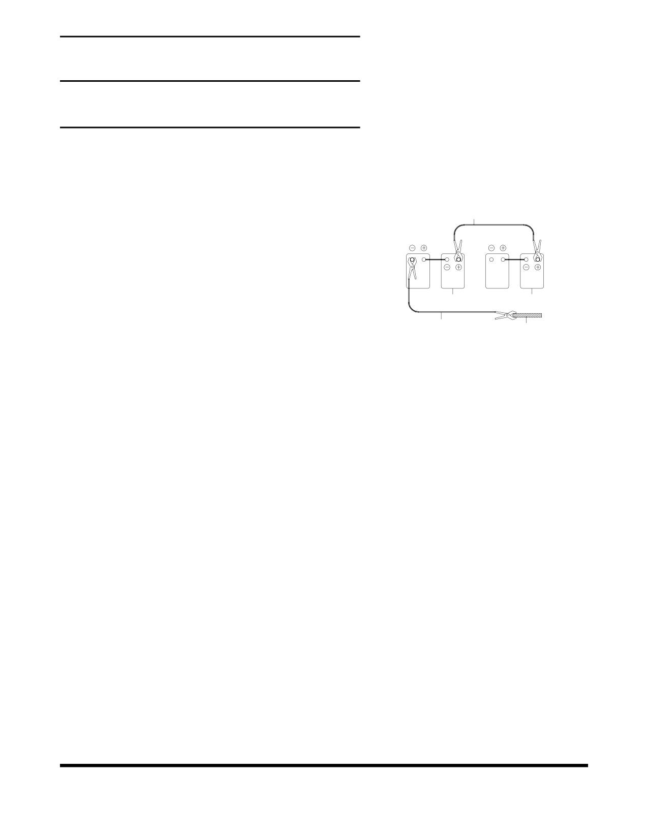
Connecting the Booster Batteries
1
1.
Shut down engine of the machine on which booster
RED
batteries (3, Figure 12) are mounted.
2.
Connect one end of red cable (1, Figure 12) to the
positive (+) terminal of the machine batteries (4), and
the other end to the positive (+) terminal of the booster
batteries.
3
4
3.
Connect one end of black cable (2, Figure 12) to the
BLACK
negative (-) terminal of the booster batteries (3), and
2
5
then make ground connection to the upper frame (5) of
ARO0440L
the machine to be started with the other end of black
Figure 12
(-) cable
(2, Figure
12). When making the last
connection to upper frame, be sure to connect the
cable end as far away from the machine batteries as
possible. DO NOT CONNECT DIRECTLY TO THE
NEGATIVE BATTERY TERMINAL.
4.
Start the engine.
Disconnecting the Booster Batteries
1.
Disconnect black negative (-) cable (2, Figure 12) from
the machine frame (5) first.
2.
Disconnect the other end of black negative (-) cable (2,
Figure 12) from the booster batteries (3).
3.
Disconnect red positive (+) cable (1, Figure 12) from
the booster batteries (3).
4.
Disconnect red positive (+) cable (1, Figure 12) from
the machine batteries (4).
Operation
OP000483
3-8
Hydraulic System Warm-up
WARNING!
If a problem or abnormal operation occurs, immediately
shut down engine. Allow excavator to reach normal
operating temperature before starting work, especially in
cold weather.
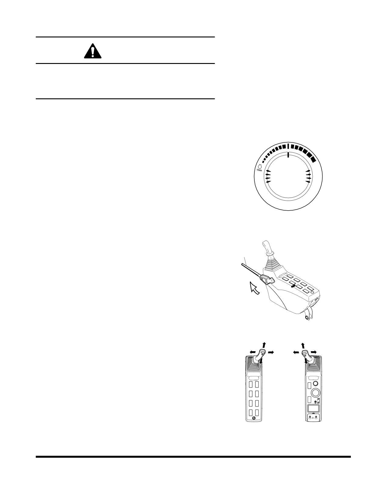
The correct operating temperature of the hydraulic oil is 50°
- 80°C (120° - 175°F). Make sure to follow the procedures
listed here for hydraulic fluid warm-up.
1.
Run engine for approximately five minutes set at the
middle of the speed range, without a load.
HAOB410L
Figure 13
2.
Set safety lever (1, Figure 14) on "UNLOCK" position.
1
FG000093
Figure 14
3.
Slowly cycle boom, arm and bucket cylinders about five
times without a load to circulate the oil through the
system. Do this for five minutes.
4.
Check for clearance and fully raise the front
attachment. Swing clockwise
3 revolutions. Swing
counterclockwise 3 revolutions.
5.
Travel forward and reverse at low speed for two
revolutions of the drive sprocket.
FG000380
Figure 15
OP000483
Operation
3-9
Hydraulic System Warm-up - Cold
Weather
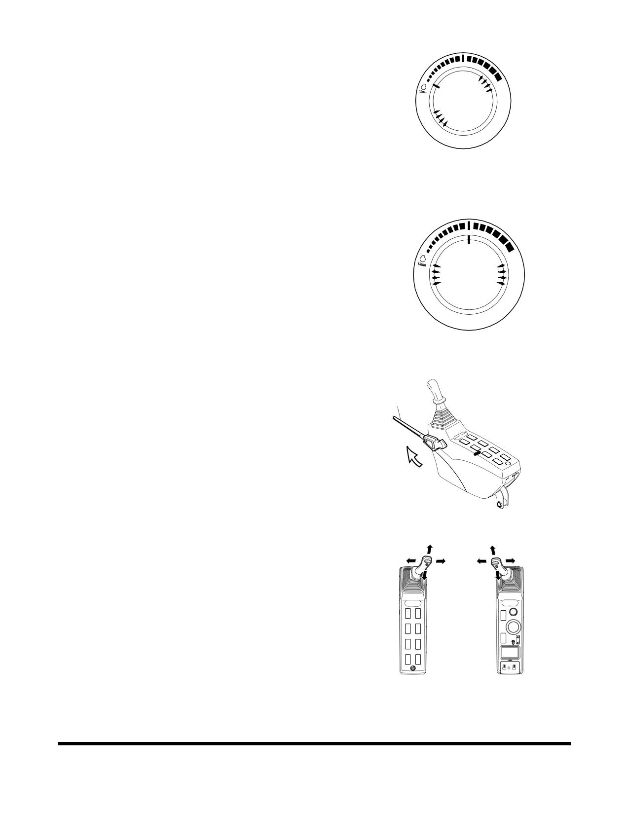
1.
Run engine at "LOW IDLE" (no load) for five minutes
(Figure 16).
HAOB290L
Figure 16
2.
Run engine for approximately five minutes set at the
middle of the speed range, without a load (Figure 17).
HAOB410L
Figure 17
3.
Set safety lever (1, Figure 18) on "UNLOCK" position.
1
FG000093
Figure 18
4.
Slowly cycle boom, arm and bucket cylinders about five
times without a load to circulate the oil through the
system. Do this for five minutes.
FG000380
Figure 19
Operation
OP000483
3-10
5.
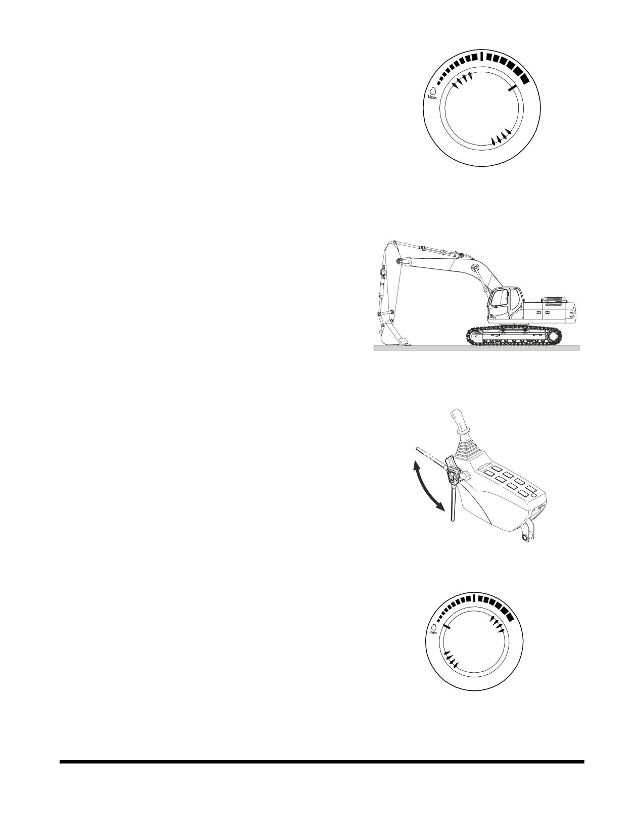
Set engine speed control dial to "HIGH IDLE" (Figure
20).
6.
Repeat Step
4 for five minutes. If working speeds
continue to be slow, continue to operate, but use
extreme caution because the machine function may be
erratic.
7.
Check for clearance and fully raise the front
attachment. Slowly swing clockwise
3 revolutions.
Slowly swing counterclockwise 3 revolutions.
8.
Travel forward and reverse at low speed for two
HAOB550L
revolutions of the drive sprocket.
Figure 20
Engine Shut Down
NOTE:
Allow engine to idle for three - five minutes before
shutting down the engine. If not allowed to idle, heat
surge may develop which will damage the engine.
Allowing the engine to idle will dissipate heat.
1.
Park excavator on level and firm ground.
2.
Lower front end attachment to ground and make sure
all operating controls are in "NEUTRAL."
FG006915
Figure 21
3.
Set safety lever on "LOCK" position (Figure 22).
Unlock
lock
FG001091
Figure 22
4.
Set engine speed control dial to "LOW IDLE" (Figure
23). Allow engine to idle for three - five minutes.
HAOB290L
Figure 23
OP000483
Operation
3-11
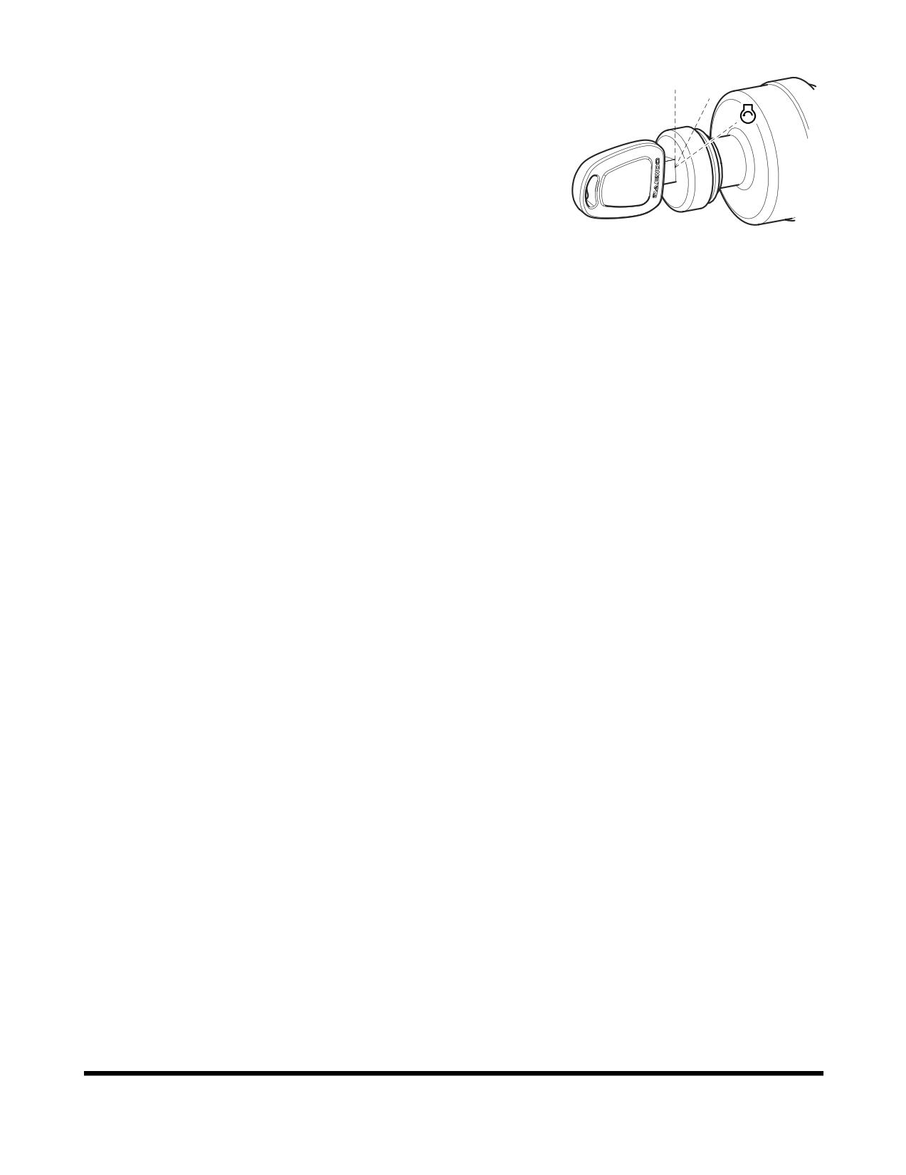
5.
Shut down engine by turning key to "O" (OFF) position
(Figure 24).
O I
6.
Remove key from starter switch.
Check and Confirmation After Stopping
Engine
1.
Repair excavator, if there are any coolant or oil leaks.
2.
Inspect front attachment and under carriage for
FG000390
abnormal appearances. Correct any problems.
Figure 24
3.
Fill fuel tank.
4.
Get rid of any accumulated flammable materials such
as leaves and paper etc. in engine compartment.
5.
Clean all mud, etc. from undercarriage and tracks.
Make sure that all steps and hand holds are clean,
and that the operator's compartment is clean.
Operation
OP000483
3-12
SAFETY LEVER
WARNING!
When stopping engine or leaving the operator's seat,
"LOCK" the safety lever, otherwise, a serious accident may
occur by accidental movement of travel and work levers.
Whenever leaving the operator's seat, make sure the engine
is shut down and the safety lever is "LOCKED."
Especially, when adjusting the seat, control stands, or
raising the front window, lower window, or ceiling cover,
never forget to lock the safety lever in its "LOCKED"
position.
Be careful not to move the work levers (joysticks) when
moving safety lever.
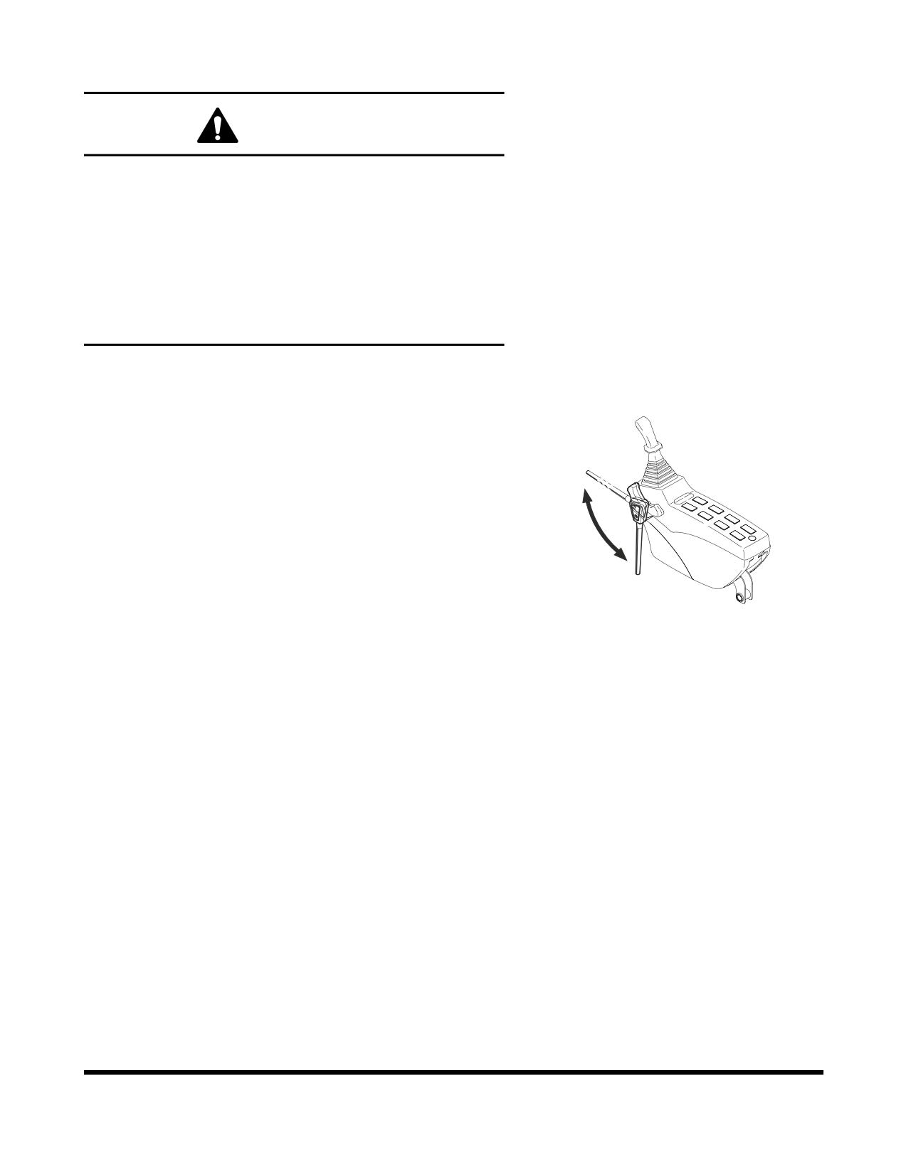
1.
Push safety lever (Figure 25) down into the "LOCKED"
position. When safety lever is in the "LOCKED"
position, the front attachment, swing and travel
movement will be disabled even though a lever is
Unlock
moved.
NOTE:
Lower bucket (front attachment) to ground.
Place all control levers in "NEUTRAL" and shut
down engine, before using the safety lever.
2.
Set safety lever (Figure
25) on "RELEASE/UNLOCK"
lock
position, by pulling it up before starting work.
FG001091
NOTE:
When the engine is not running, but the safety
Figure 25
lever is "RELEASED" and the starter key is
tuned "ON," moving the work levers (joysticks)
may result in movement. The charged
accumulators in the system will provide pilot
pressure for control valve spool movement.
OP000483
Operation
3-13
TRAVEL
WARNING!
1.
Before operating the travel levers, make sure that
you know in which direction the machine is
pointing. Look at the end of the track assemblies. If
the drive motors are visible while sitting in the
operator's seat, you are looking at the back end of
the track assembly (therefore, you are looking
backwards). In this case, the response of the travel
levers will be the reverse of normal operation.
2.
Before moving, make sure that there are no
personnel in the way or on the machine. Sound the
horn to alert workers that you are about to move
the machine.
3.
Be sure the path is clear during travel.
4.
Use extreme caution when reversing travel. Be sure
there is a clear path behind the machine.
5.
Make sure to operate the travel control levers
smoothly to avoid sudden starts or stops.
6.
Before leaving the operator's seat, make sure to
lock out all control systems and shut down the
engine to avoid accidental activation.
Automatic Travel Speed Control
WARNING!
Do not change the travel mode while traveling. Always use
speed mode "O" when traveling down a slope. It is very
dangerous to change to speed modes indicated "I" or "II"
while going down a slope. Only change travel mode after
coming to a complete stop.
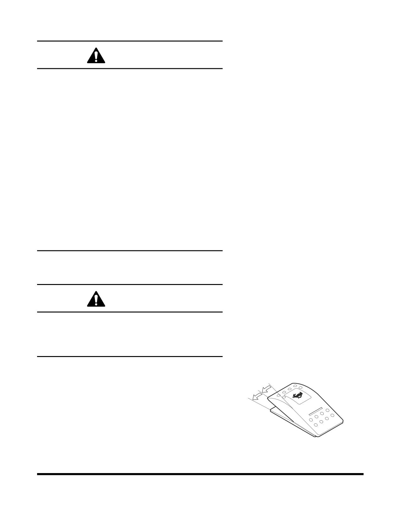
Two travel speed ranges can be selected by using the travel
speed selector switch on the control panel (Figure 26).
O
"O" (LOW) - In this position low travel speed and a higher
I
torque are selected.
II
"I" (HIGH) - In this position high travel speed and a lower
torque are selected.
"II" (AUTOMATIC) - Setting the control at the "II" position
enables the machine to change to a different speed range
automatically. This change happens automatically depending
on the hydraulic oil pressure in the travel circuit. When
FG000023
hydraulic oil pressure rises, the travel speed is automatically
Figure 26
set to low. An example is if the machine is traveling on a
Operation
OP000483
3-14
flat, solid surface, the higher speed range would be used.
When a slope is encountered, the speed drops and the
travel circuit hydraulic pressure rises, causing the control
circuit to shift to the higher torque, lower speed range.
OP000483
Operation
3-15
Travel Control Lever Operation
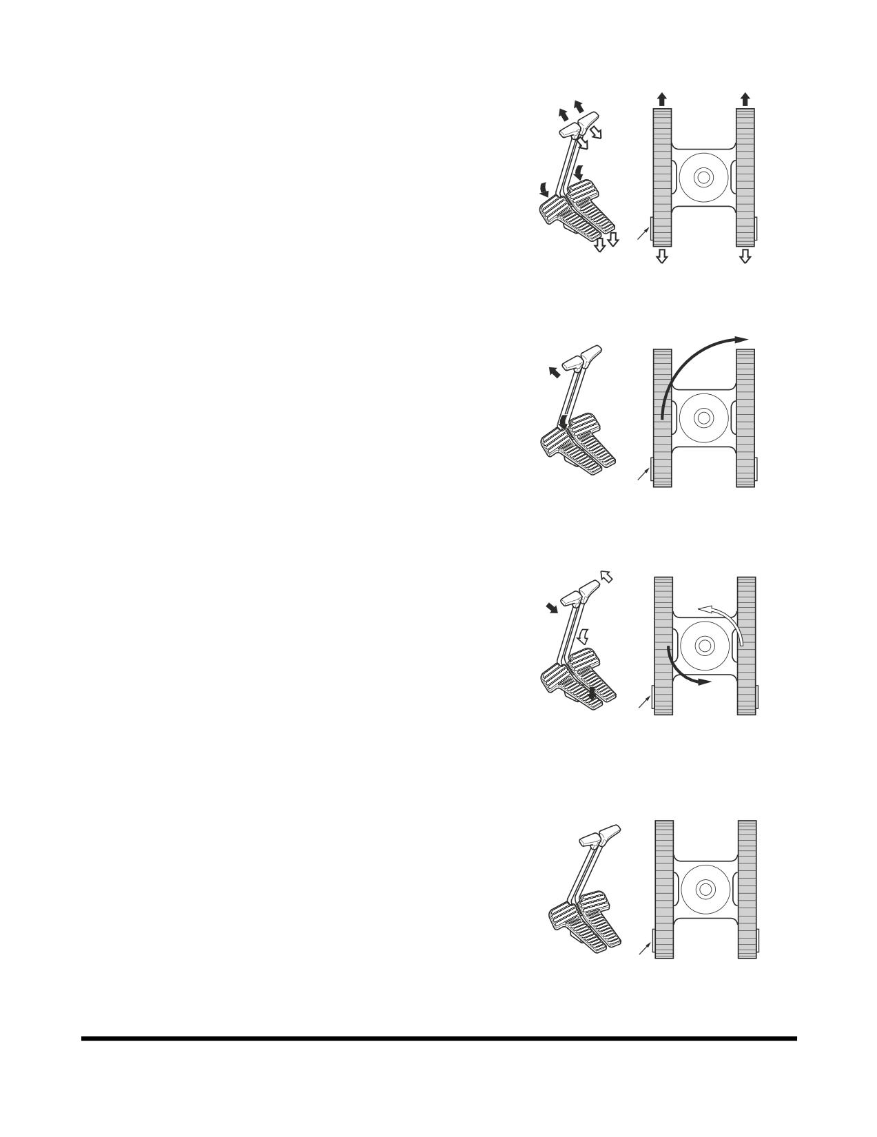
1.
To travel straight (Figure 27), push both travel control
levers/pedals fully forward or backwards. The farther
the levers/pedals are pressed, the faster the travel
speed.
NOTE:
"X" is the sprocket end of the track.
"X"
FG000303
Figure 27
2.
Pivot turns (Figure 28) are made by rotating only one
track forward or backward. The machine will pivot on
the nonmoving track.
NOTE:
"X" is the sprocket end of the track.
"X"
FG000304
Figure 28
3.
Spin turns (Figure 29) are made by rotating one track
forward and one track backward. The machine will spin
around its center point, thus counterrotating.
NOTE:
"X" is the sprocket end of the track.
"X"
FG000305
Figure 29
4.
Stopping travel (Figure 30) - Returning travel levers to
"NEUTRAL" position will automatically apply brakes and
stop excavator.
NOTE:
"X" is the sprocket end of the track.
"X"
FG000306
Figure 30
Operation
OP000483
3-16
General Travel Instructions
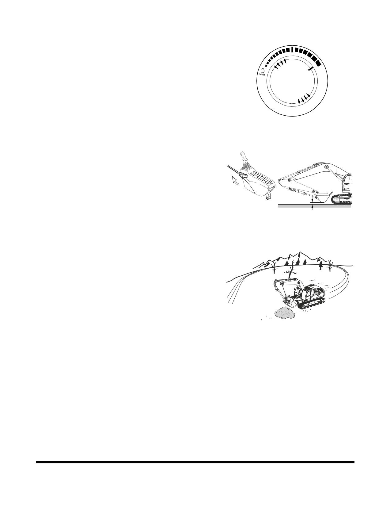
1.
Set engine speed control dial (Figure 31) on desired
speed.
HAOB550L
Figure 31
2.
Set safety lever on "UNLOCK" position, and folding the
front, raise it 40 - 50 cm (16 - 20 in) above ground.
See Figure 32.
40 ~ 50 cm
FG000123
Figure 32
3.
When possible, travel on firm, level ground. Avoid
sudden movements and sharp turns.
4.
When traveling on rough ground, travel at a slow
speed [1.0 - 1.5 km/h
(0.62
- 0.93 MPH)]. Reduced
engine speed, to avoid shock loading the equipment.
Be careful that an excessive force is not added to
equipment by touching or climbing on rocks.
FG000423
Figure 33
OP000483
Operation
3-17
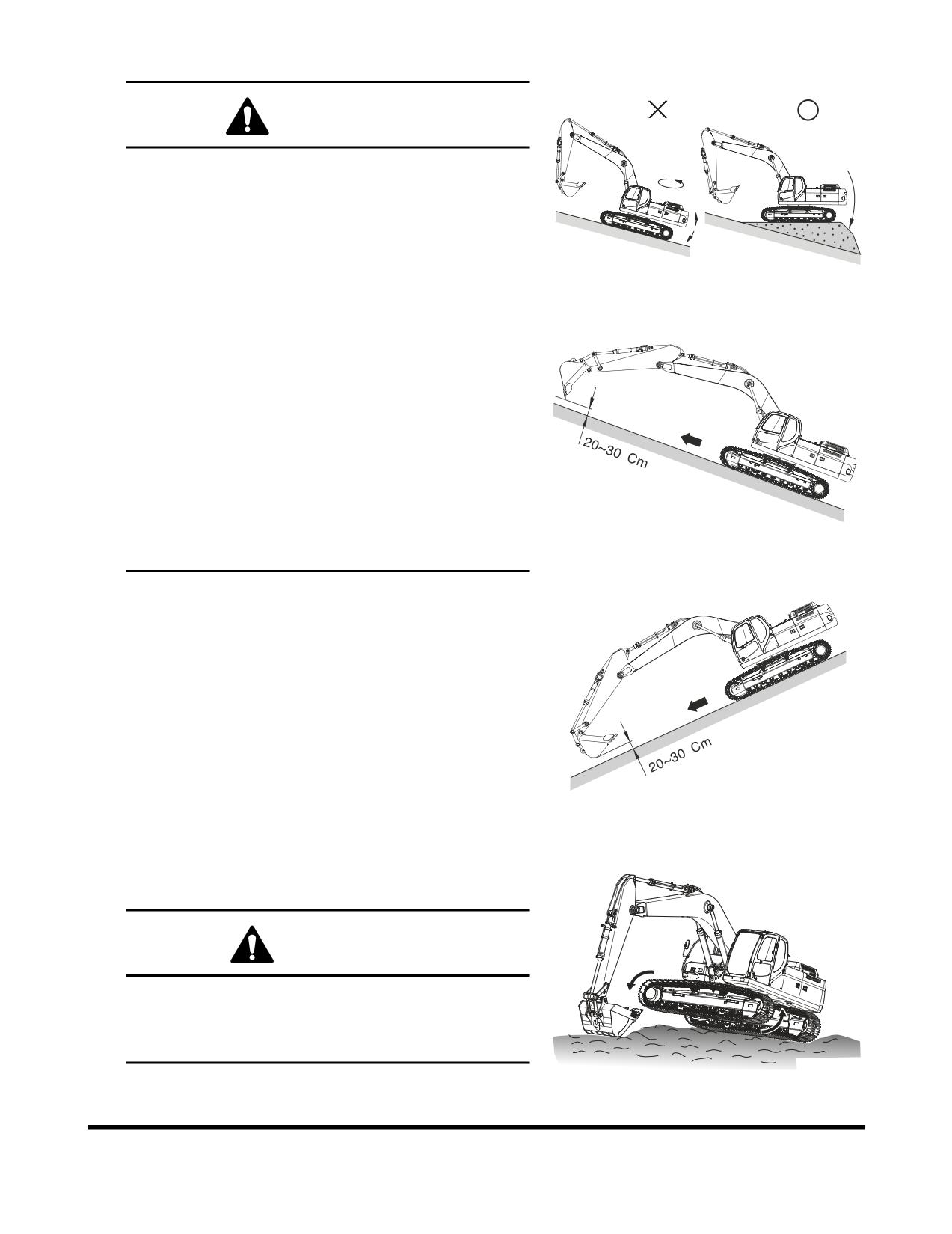
5.
On rough, frozen or uneven terrain, travel slowly.
WARNING!
When traveling, keep bucket from 20 - 30 cm (8 - 12 in)
above ground.
Do not travel backward on a slope.
Never turn or travel crosswise on a slope.
Choose a safe alternate route before climbing a slope.
FG006916
If excavator starts to slip or becomes unstable, lower
Figure 34
the bucket immediately into the ground, using it as a
brake.
Avoid working on slopes, because there is a danger of
overturning by becoming unbalance while swinging
and performing front attachment operations.
It is very dangerous to swing towards bottom of slope
with a loaded bucket.
In unavoidable cases level the slope with fill soil,
to make the vehicle as horizontal as possible. See
Figure 34.
FG006917
Do not travel on slopes more than 30° due to turnover
danger.
Figure 35
6.
Travel straight up or down slopes, never diagonally
across the slope. See Figure 35 and Figure 36. Extend
the arm and lower the boom to keep the bucket about
20 - 30 cm (8 - 12 in) off the ground. If the machine
starts to slide or becomes unstable, lower the bucket to
regain control. If the engine stalls, lower the bucket,
make sure that all controls are in the neutral position
and restart the engine.
NOTE:
Even though engine stops on a slope, do not
operate swing control. The hydraulic
accumulators may cause the unit to swing.
FG006918
Figure 36
NOTE:
Do not open or close operator's door on a slope.
Make sure door is latched.
7.
If dirt or mud builds up in the track frame, raise each
track and rotate and clean that track.
CAUTION!
When using the boom and arm to lift any portion of the
machine, roll the bucket until the round base is against
the ground. The angle of the arm to the boom should
be at 90°.
FG000376
Figure 37
Operation
OP000483
3-18
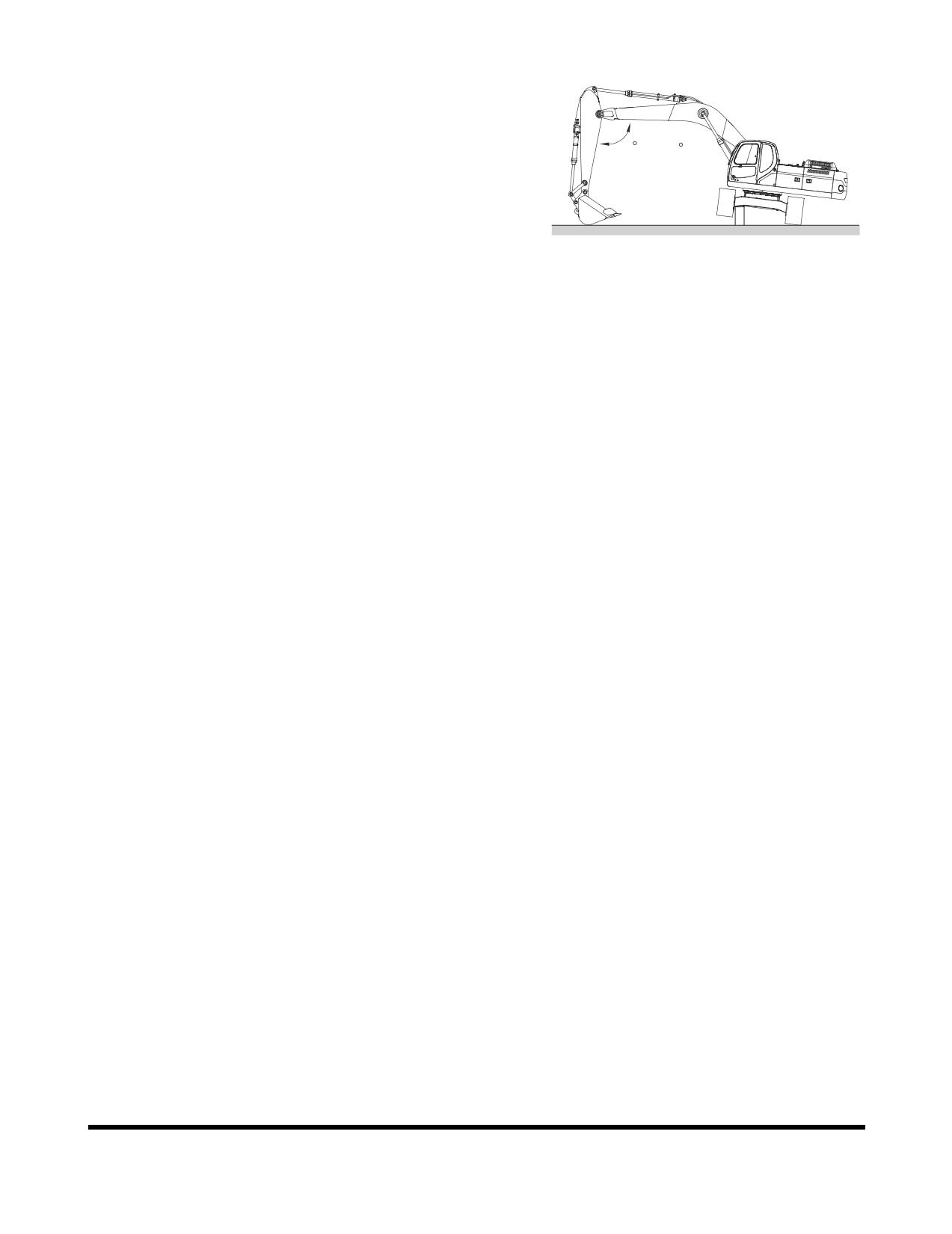
Make sure that the material buildup has been cleared.
See Figure 37 and Figure 38.
8.
The excavator can travel in water that comes up to
center of upper carriage rollers. Make sure that footing
is solid so that the machine will not sink. See “Working
90 ~ 110
in Water” on page 3-30.
NOTE:
If the machine is submerged to the point that
water or mud gets into the swing bearing or
center joint, stop machine operation. Remove
the machine from the submerged location to
FG006919
firm, dry ground. Do not operate until proper
Figure 38
inspection and maintenance have been
completed. Refer to the Shop Manual or contact
your distributor.
OP000483
Operation
3-19
OPERATING INSTRUCTIONS
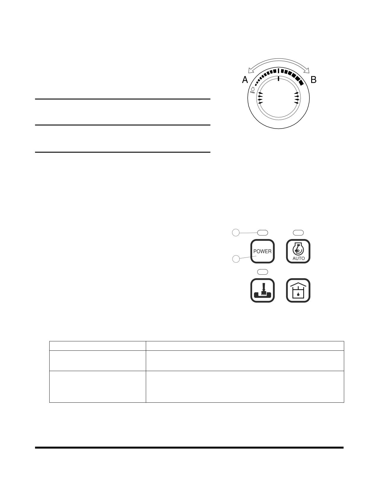
Engine Speed Control
Engine speed can be manually adjusted using the engine
speed control dial, Increase engine speed by rotating the
control knob clockwise. Decrease engine speed by rotating
the control knob counterclockwise.
IMPORTANT
The engine speed control system has been set at the
HAOA690L
factory and should not require adjustment as part of routine
Figure 39
maintenance.
Mode Selection
More efficient work can be done by choosing a proper
power and work mode combination, suitable to type of work
and conditions. Use the mode selection according to
following guide.
Power Mode
2
1.
When the starter switch is turned "ON" the power
mode is automatically defaulted to the standard setting.
2.
Select a proper power mode using button (1, Figure
1
40) before starting work.
1
2
3.
When the power mode button
(1, Figure
40) is
pressed, a signal sounds, changing the power mode to
either "ON" or "OFF." When the power mode is turned
"ON," the LED indicator (2, Figure 40) turns "ON."
5
6
FG000114
Deactivate the power mode by pressing it a second
Figure 40
time. When the power mode is turned "OFF," the LED
indicator
(2, Figure
40) turns "OFF" and the power
mode returns to the standard mode.
Mode
Selection Point
• General work.
STANDARD MODE
• Minimize fuel consumption.
• Required to perform heavy work in a short period of time.
POWER MODE
• Fast speed loading.
• Fast speed travel.
Operation
OP000483
3-20
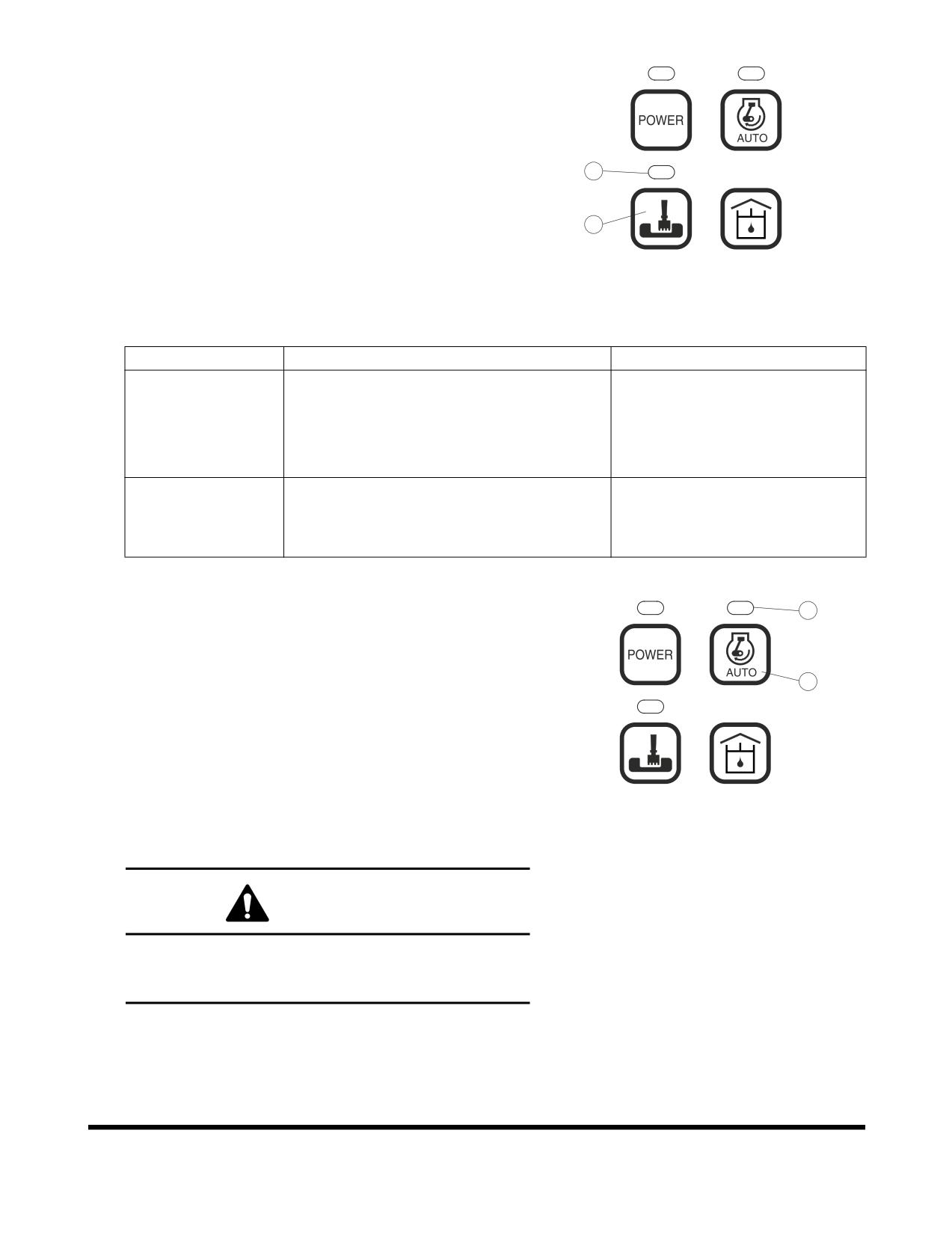
Work Mode
1.
When the starter switch is turned "ON" the work mode
is automatically defaulted to the digging mode.
2.
Select the work mode using button
(3, Figure
41)
before starting work.
1
2
4
3.
When the work mode button (3, Figure 41) is pressed,
a signal sounds, changing the work mode to either
"Digging Mode" or "Trenching Mode." When the
3
trenching mode is selected, the LED indicator
(4,
5
6
Figure
41) turns "ON." When the digging mode is
FG000115
selected, the LED indicator (4, Figure 41) turns "OFF."
Figure 41
4.
When the trenching mode is selected, the control valve
is set to optimum condition for trenching work.
Mode
Selection Point
Feature of Control
• General excavation.
General standard.
• Loading dump trucks.
DIGGING MODE
• Lifting and transport of heavy objects.
• Breaker.
• Trenching.
TRENCHING
The swing is faster and stronger
• Excavating of side wall.
MODE
than boom or arm.
• Required to constant swinging.
Auto Idle Mode
6
1.
The system will automatically reduce engine speed to
idle speed approximately four seconds after all of the
control levers are in the neutral position. When a pilot
function is activated, engine speed is automatically
5
1
2
returned to the preselected range.
2.
When the starter switch is turned "ON," the work mode
is automatically defaulted to "AUTO IDLE."
3.
When the LED indicator (6, Figure 42) is turned "ON,"
5
6
the auto idle function is activated. Deactivate the auto
FG000116
idle function by again pressing the auto idle selector
Figure 42
button (5, Figure 42). At this time the LED indicator will
be turned "OFF."
WARNING!
Turn "OFF' auto idle function when performing work in
close operating area, i.e., work in a narrow area and
loading / unloading on or off a trailer.
OP000483
Operation
3-21
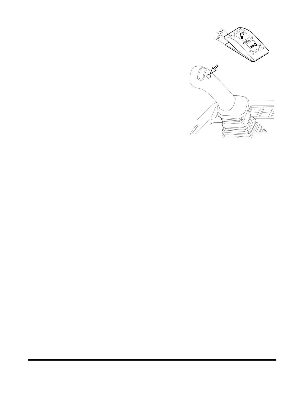
Boost Mode
I
1.
Power boost switch is used to gain maximum digging
O
force.
I
2.
The power boost is activated while the lower button is
being pressed on top of the right-hand work lever
(joystick). The breaker / boost / shear selector switch
must be in the "O" (BOOST) position.
NOTE:
The power boost mode does not affect forward
and reverse travel.
Do not use this switch for more than ten
seconds.
FG000117
Figure 43 RIGHT-HAND WORK LEVER
(JOYSTICK)
Operation
OP000483
3-22
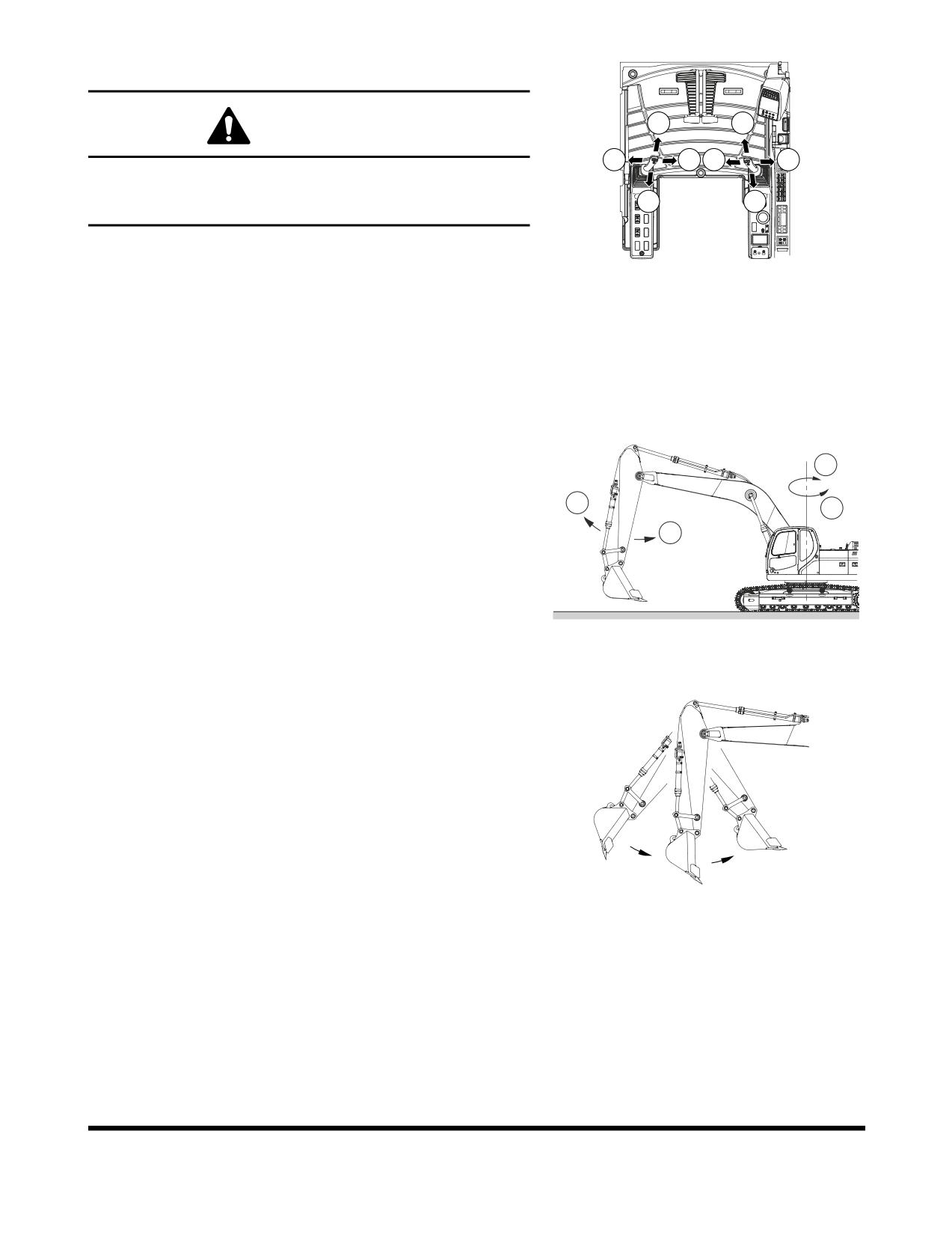
Work Levers (Joysticks) (ISO Style)
1
5
WARNING!
3
4
7
8
Check surrounding area before swinging. When operating a
lever while in auto idle, do it carefully, because the engine
2
6
speed will increase rapidly.
NOTE:
When starting work, move work levers (joysticks)
FG000381
slowly and check movement of swing and front
Figure 44
attachment.
This equipment is manufactured using the lever configuration
described in ISO standards. Do not change valving, hoses,
etc., that would change this standard. The boom, arm and
bucket movements and swing direction of work levers
(joysticks) are as follows:
Left-hand Work Lever (Joystick) (Figure 44 and Figure
45)
4
1.
Arm dump
1
3
2.
Arm crowd
2
3.
Left swing
4.
Right swing
NOTE:
The swing brake is spring applied and
hydraulically released. It is always engaged
when the work lever (joystick) is in "NEUTRAL"
FG006920
or the engine is shut down.
Figure 45
NOTE:
The following is not a mechanical malfunction
but a proper phenomenon of the excavator.
When operating the arm, it may stop
momentarily. When the arm is operated, the
weight of the arm may cause it to move faster
than the amount of oil being supplied.
FG000120
Figure 46
OP000483
Operation
3-23
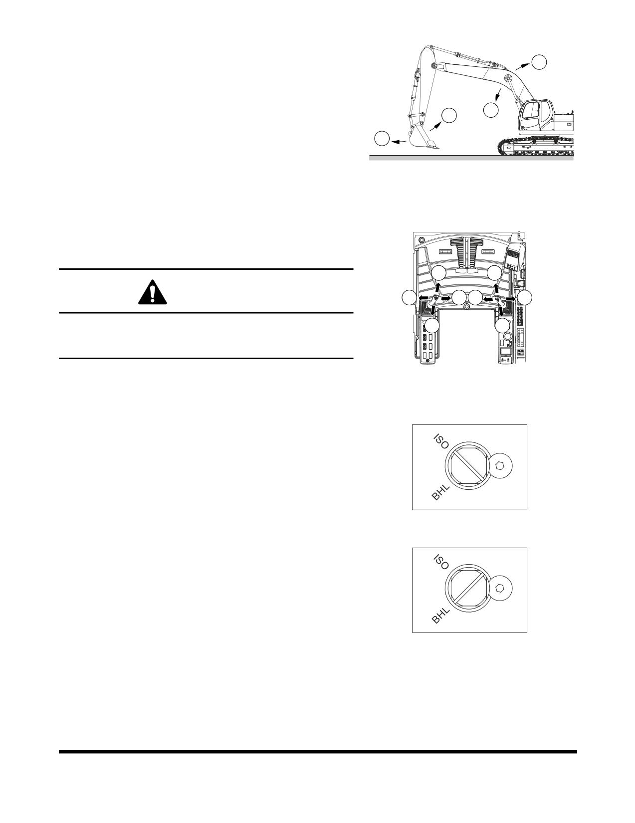
Right-hand Work Lever (Joystick) (Figure 44 and Figure
47)
6
5.
Boom down
6.
Boom up
7.
Bucket crowd
5
7
8.
Bucket dump
8
NOTE:
Even after stopping the engine, the front can be
lowered to the ground by operating work lever
(joystick), by setting safety lever on "UNLOCK"
FG006921
position and turning starter switch "ON."
Figure 47
Change Machine Control Pattern by
Select Valve (If Equipped)
1
5
WARNING!
3
4
7
8
Check surrounding area before swinging. When operating a
2
6
lever while in auto idle, do it carefully, because the engine
speed will increase rapidly.
FG000381
Figure 48
NOTE:
When starting work, move work levers (joysticks)
slowly and check movement of swing and front
<ISO PATTERN>
attachment.
The machine control pattern can easily be changed to the
ISO standard or to the standard backhoe loader hydraulic
system (BHL) by changing the position of the select valve (if
equipped). Use the following procedure to change the
position of the select valve.
The select valve is located in the rear of the cabin.
1.
Rotating spool to the ISO position or to the BHL
<BHL PATTERN>
position. (Figure 49)
FG004954
Figure 49
Operation
OP000483
3-24
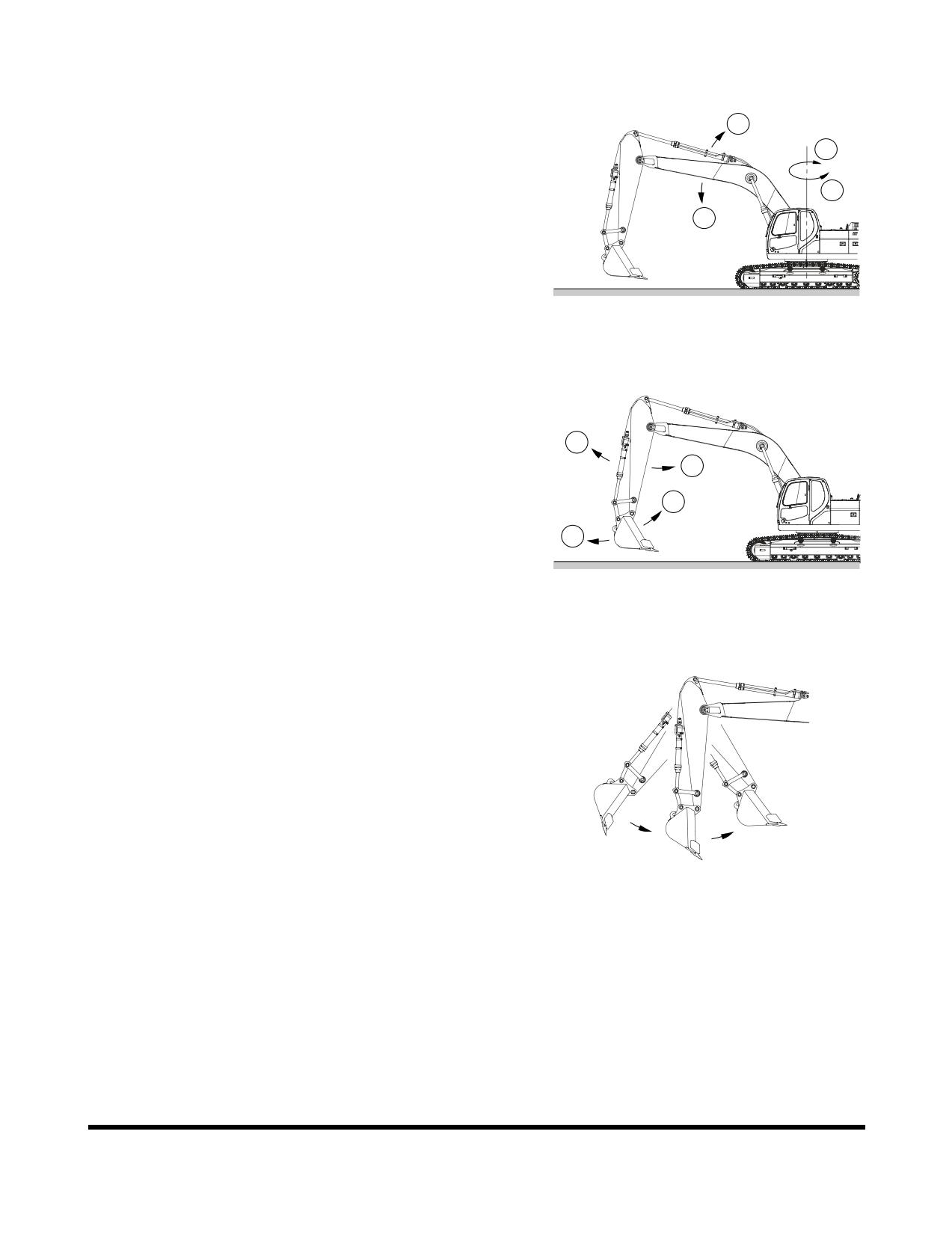
Work Levers (Joysticks) (BHL Style)
Left-hand Work Lever (Joystick) (Figure 48 and Figure
2
50)
4
1.
Boom down
2.
Boom up
3
3.
Left swing
1
4.
Right swing
NOTE:
The swing brake is spring applied and
hydraulically released. It is always engaged
when the work lever (joystick) is in "NEUTRAL"
FG006938
or the engine is shut down.
Figure 50
Right-hand Work Lever (Joystick) (Figure 48 and Figure
51)
5.
Arm dump
5
6.
Arm crowd
6
7.
Bucket crowd
7
8.
Bucket dump
8
NOTE:
The following is not a mechanical malfunction
but a proper phenomenon of the excavator.
FG006939
When operating the arm, it may stop
momentarily. When the arm is operated, the
Figure 51
weight of the arm may cause it to move faster
than the amount of oil being supplied.
NOTE:
Even after stopping the engine, the front can be
lowered to the ground by operating work lever
(joystick), by setting safety lever on "UNLOCK"
position and turning starter switch "ON."
FG000120
Figure 52
OP000483
Operation
3-25
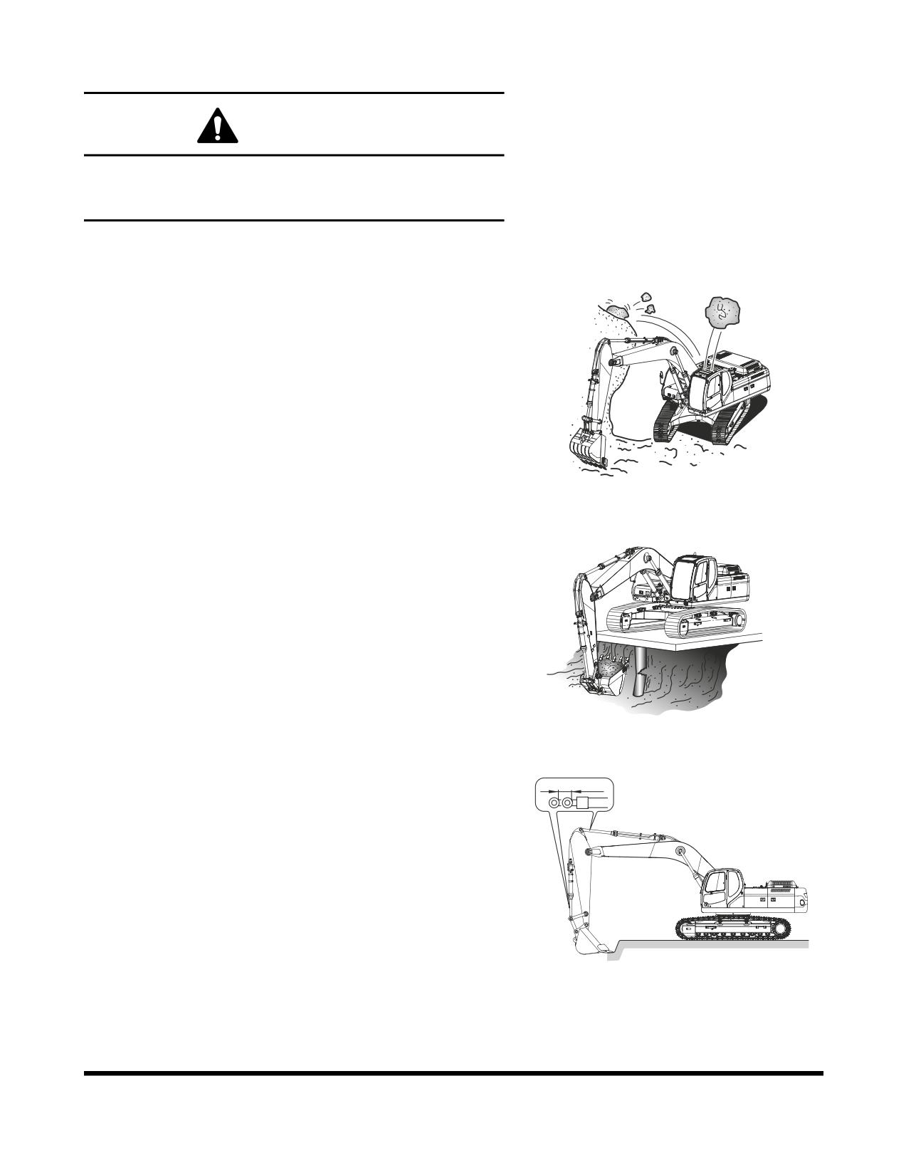
OPERATING PRECAUTIONS
WARNING!
Do not rest your feet on the travel pedals during normal
machine operation. Unexpected machine travel may occur
in this situation.
1.
Before starting work, investigate terrain and soil
condition. Level ground and drain area if necessary.
2.
Install window guards when working where there is a
possibility of falling rocks or other objects.
FG000374
Figure 53
3.
Check strength of supported structures in advance
before working on them. If insufficient, reinforce it. If
any doubt exists about structural strength, refuse to
operate unit.
4.
It is possible that the boom, arm or bucket may come
into contact with the upper or lower structure of the
machine. There are digging conditions which could
allow this to happen.
FG000375
Figure 54
5.
Do not continually "bottom out" the hydraulic cylinders.
Machine damage may occur if the cylinders are fully
extended or retracted, example: arm cylinder fully
retracted and the bucket cylinder is extended to rotate
the bucket into the ground.
FG006922
Figure 55
Operation
OP000483
3-26
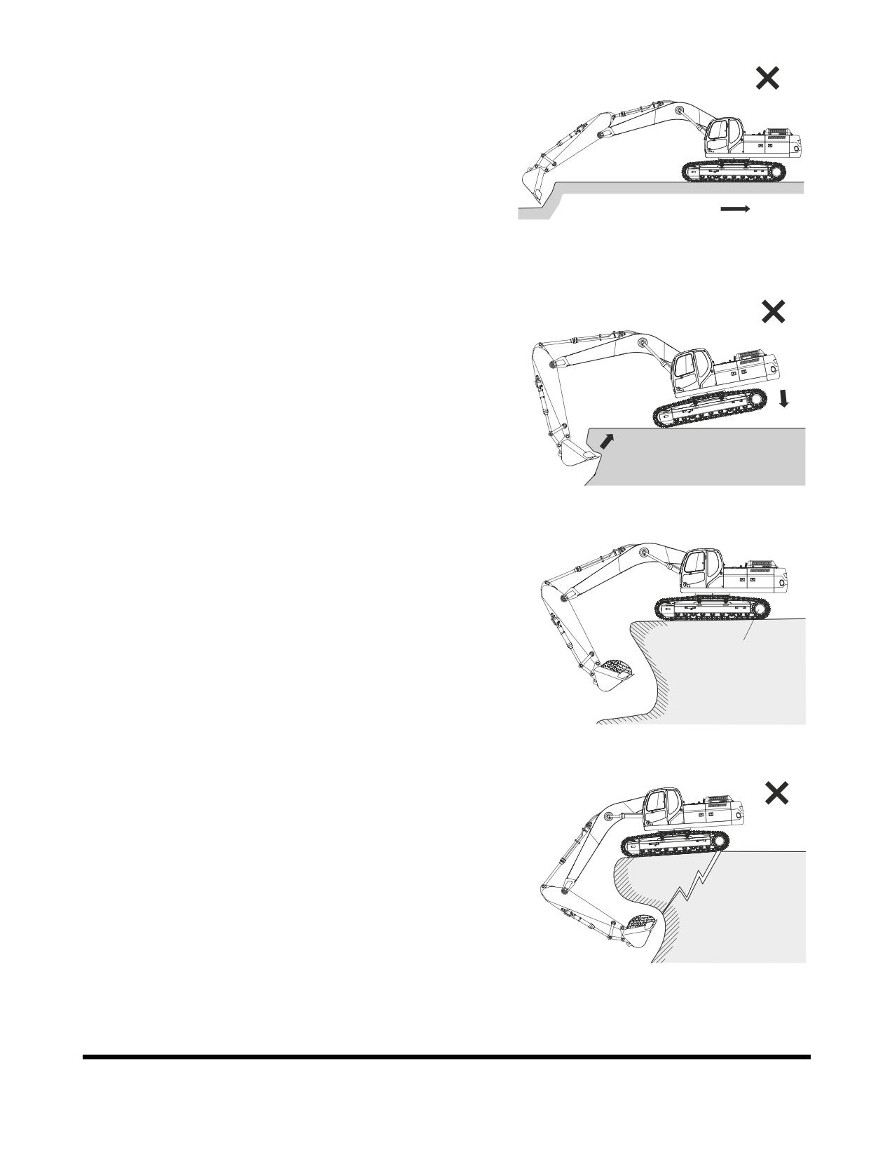
6.
Do not use machine travel or swing when the bucket is
in the ground to provide additional breakout force. See
Figure 56.
FG006923
Figure 56
7.
Do not use machine weight to provide additional
breakout force. See Figure 57.
8.
When working on soft or muddy ground, make sure
that the machine is not sinking.
FG006924
Figure 57
9.
When working close to the excavated edge, make sure
that the ground the machine is sitting on is solid. Keep
the travel motors (1, Figure 58) to the rear. See Figure
58.
1
FG006925
Figure 58
10. Do not excavate underneath the machine. See Figure
59.
FG006905
Figure 59
OP000483
Operation
3-27
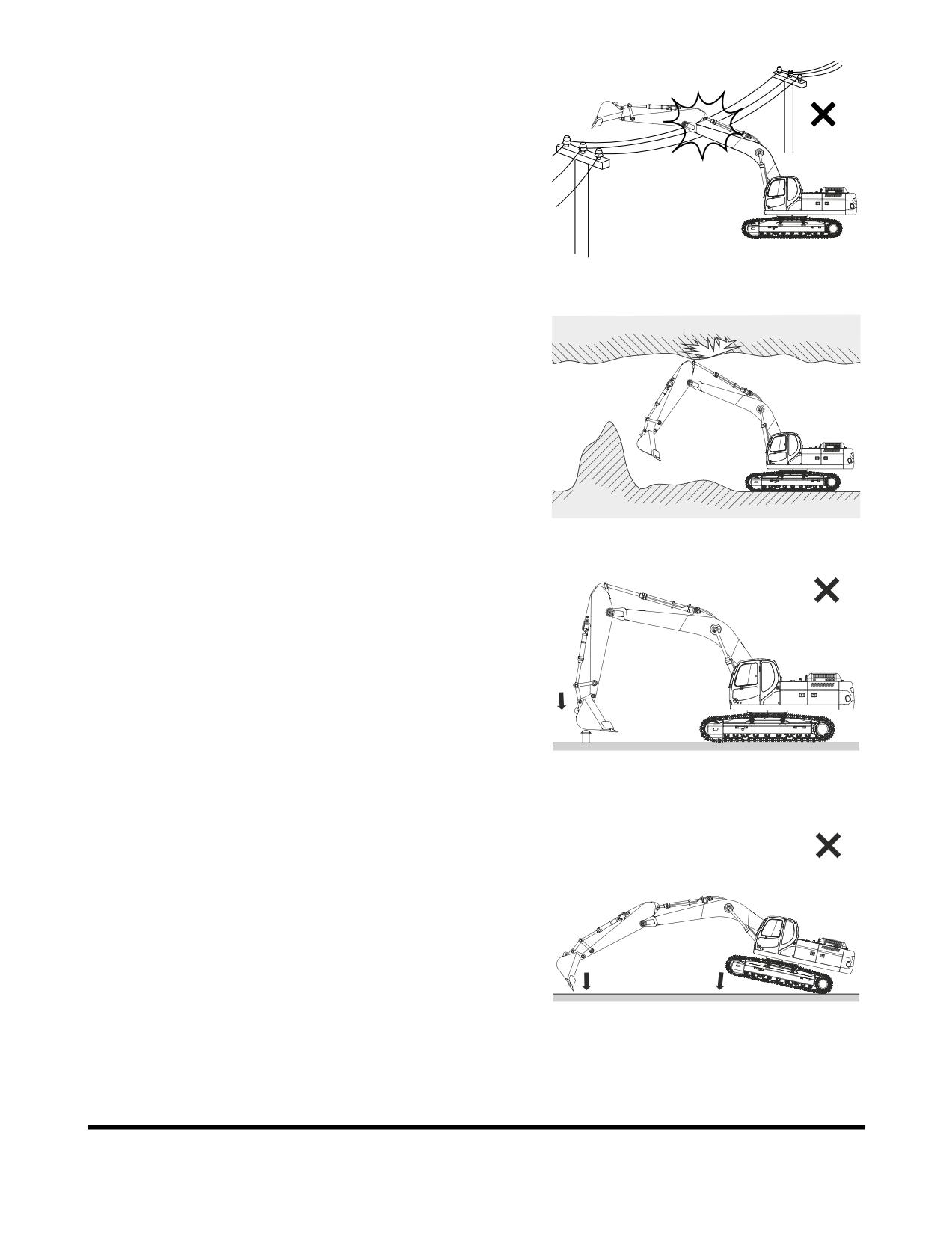
11. Make sure that there is adequate clearance from
overhead electrical supply lines. See Figure 60.
FG006907
Figure 60
12. If the excavation is in an underground location or in a
building, make sure that there is adequate overhead
clearance and that there is adequate ventilation. See
Figure 61.
FG006926
Figure 61
13. Do not use the bucket as a hammer or ramming
device. This is dangerous and causes damage to the
front attachment. See Figure 62.
FG006927
Figure 62
14. Do not dig with the excavator tracks raised. This can
result in structural and mechanical failures.
FG006928
Figure 63
Operation
OP000483
3-28
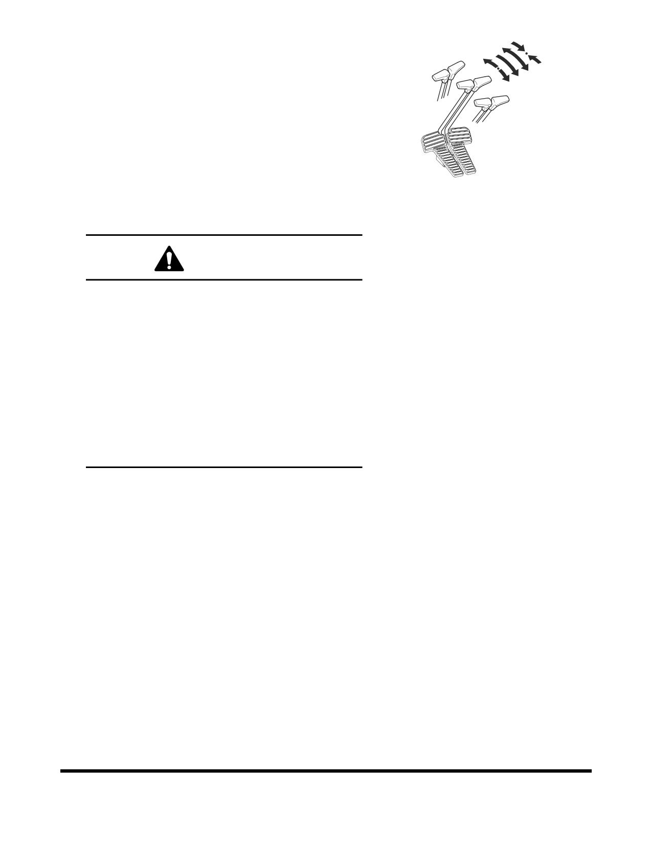
15. Do not operate travel lever quickly when traveling in
high range.
•
Avoid sudden starts.
•
When traveling in one direction come to a
complete stop before reversing directions. Do not
rock excavator back and forth with levers.
•
Avoid sudden stops. Return levers to neutral by
hand. Do not let them snap back to neutral on
their own.
FG000213
16. If the optional long fronts or attachments or heavy duty
Figure 64
front end attachments are used, the machine balance
will be altered. Follow these additional operating
precautions.
WARNING!
Do not travel downhill with the front end attachments
raised.
Do not travel across slopes; travel straight up or down
slope.
Use extreme caution when swinging the upper frame
when positioned on a slope.
Allow extra swing stopping room. The additional
momentum generated by the longer or heavier front
end equipment will increase the amount of time
needed to stop the swing motion.
Make sure that all optional equipment has been
authorized and installed properly.
17. Do not move dirt or objects by swinging the excavator
into them. This can result in structural and mechanical
failures.
OP000483
Operation
3-29
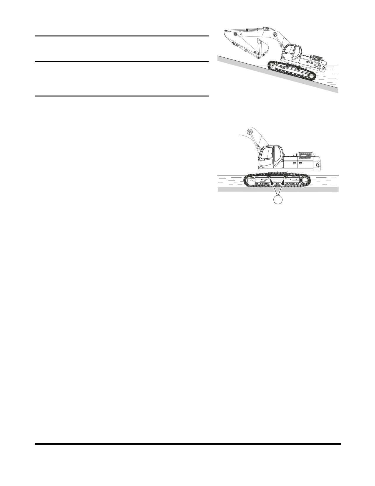
Working in Water
IMPORTANT
When working in water, do not exceed a slope of more than
15°. If the slope is over 15°, the rear part of the upper
structure will be immersed in water, resulting in radiator fan
and engine ECU damage.
FG006929
Figure 65
When working in water, do not operate in water over center
of upper roller (1, Figure 66).
If swing bearing gets wet, immediately grease it until all old
grease is purged from bearing.
If
water gets into swing gear housing, drain water
immediately by removing lower inspection cover. Apply new
grease.
After working in water, purge old grease on bucket pins.
1
FG006930
Figure 66
Operation
OP000483
3-30
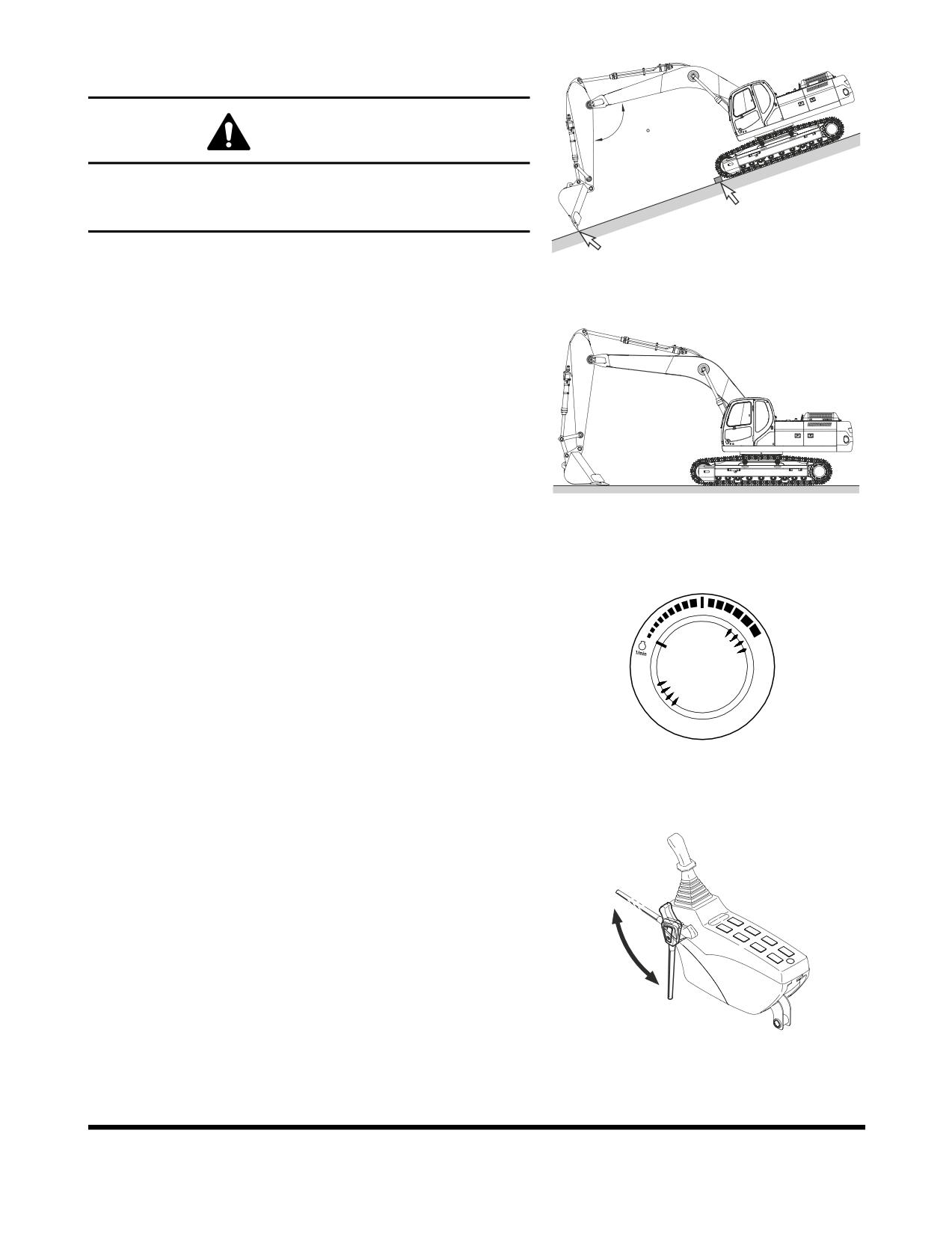
PARKING EXCAVATOR
WARNING!
120
Park excavator on firm, level ground. Avoid parking on
slopes. If excavator must be parked on a slope, block tracks
and place bucket teeth in ground. See Figure 67.
FG006931
Figure 67
1.
Park excavator on firm, level ground. Lower bucket to
ground as shown in Figure 68.
FG006932
Figure 68
2.
Set engine speed control dial on "LOW IDLE."
HAOB290L
Figure 69
3.
If you touch the operation lever unintentionally, it may
create a serious accident. Before leaving operator's
seat, set safety lever on "LOCK" position.
Unlock
lock
FG001091
Figure 70
OP000483
Operation
3-31
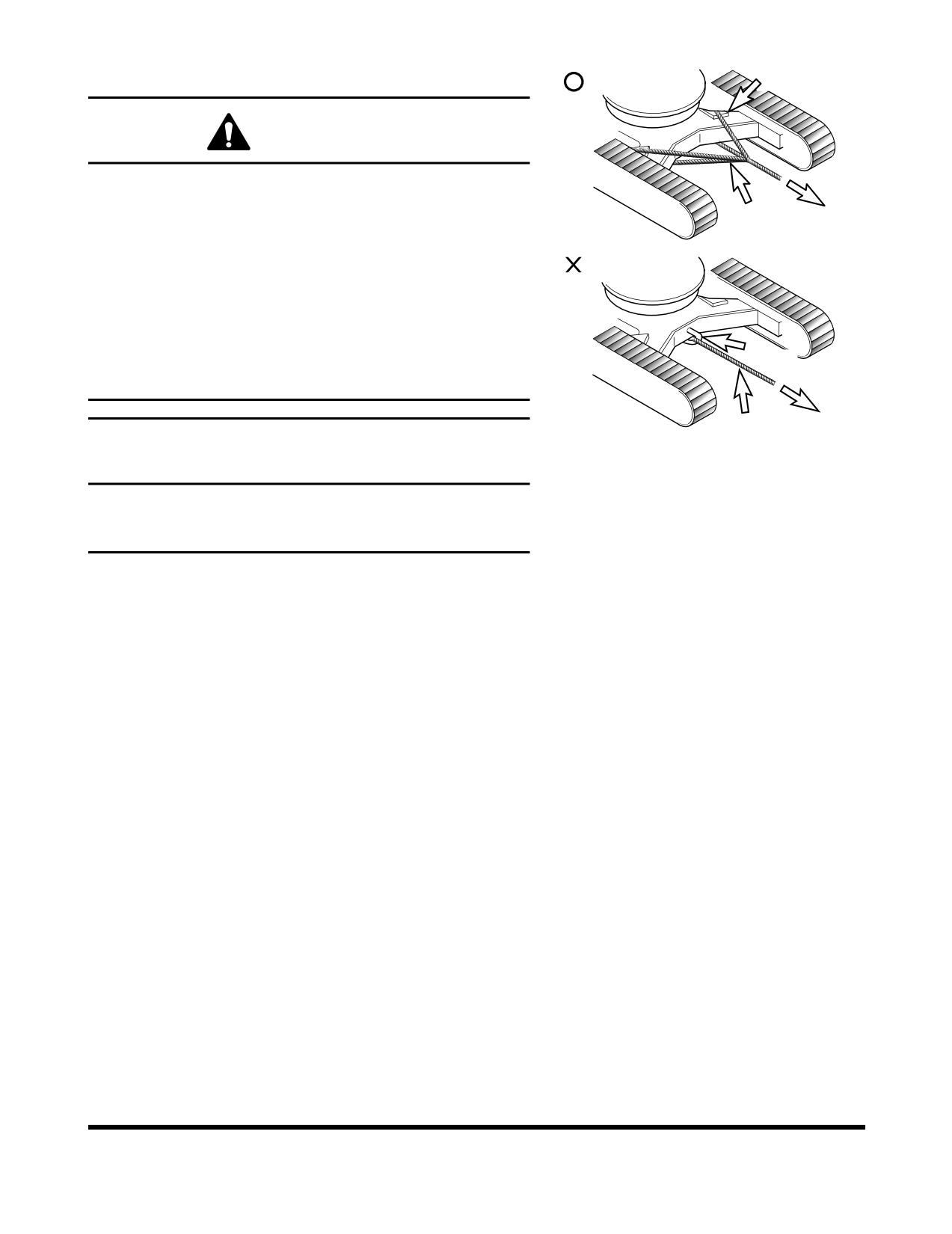
TOWING PROCEDURE
Cloth
WARNING!
Never use a damaged wire rope or chain. They could brake
and cause a serious accident.
Towing Wire
Always wear gloves when handling a chain or wire rope.
When towing excavator use a wire rope or chain capable of
handling the load.
Attach chain or wire rope to track frame as shown in
Figure 71
Insert protective material such as thick cloths between
Shackle
track frame and wire rope to prevent the wire rope from
being damage.
Towing WireFG000669
Figure 71
IMPORTANT
Use shackle hook on track frame to only haul objects that
weigh less than 5 metric tons (5.51 U.S. Tons). Never use it
to haul objects over 5 metric tons (5.51 U.S. Tons).
Operation
OP000483
3-32
HYDRAULIC BREAKER
IMPORTANT
If a hydraulic breaker and piping is installed without
DOOSAN's authorization, it may create a serious
malfunction which will not be covered under the excavator
warranty.
Selection of Hydraulic Breaker
If a hydraulic breaker is installed, consider equipment's
stability and suitability for such modification. Also, consider
hydraulic oil pressure and quantity. When selecting a
hydraulic breaker consult with a DOOSAN distributor or
sales agency.
Hydraulic Hoses and Tubing for Breaker
1.
When installing hydraulic breaker, assemble according
to drawings provided with kit.
2.
If breaker is taken off excavator, be sure to plug and
cap all hoses and tubing to prevent contamination from
entering hydraulic system.
3.
Plug and cap all connectors and fittings on breaker to
prevent contamination.
4.
Check all hydraulic connections for signs of leaks or
loose components before starting operation.
Hydraulic Breaker Operation
NOTE:
Hydraulic pressure and flow settings may need to be
changed. Refer to the Maintenance Section of this
manual for further information.
1.
Make sure to read and understand the breaker user's
manual.
2.
Inspect all mechanical and hydraulic connections.
OP000483
Operation
3-33
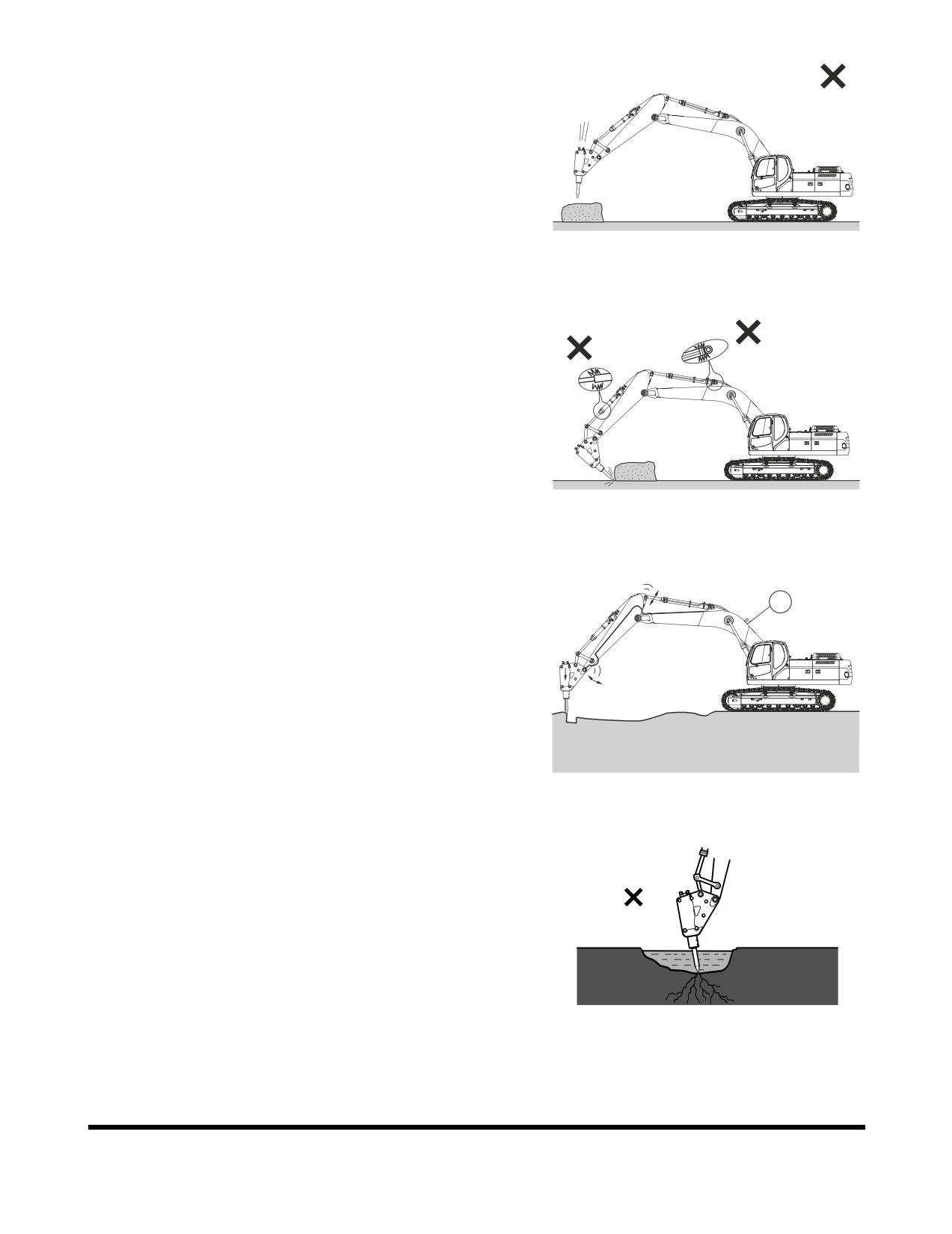
3.
Do not use the breaker as a hammer. See Figure 72.
Do not drop breaker from extreme heights.
The breaker is relatively heavy and drops fast. Do not
drop breaker from extreme heights or damage to upper
structure may result.
FG006933
Figure 72
4.
Do not operate the breaker with the boom or arm
cylinders fully extended (bottomed out). See Figure 73.
Leave over 100 mm (4 in) of clearance between rod
end of cylinder and cylinder head. This will help
prevent damage to cylinders during breaker operation.
FG006934
Figure 73
5.
Do not use the breaker if the hydraulic hoses vibrate
excessively. See Figure
74. Check the breaker's
1
hydraulic accumulator
(1) for damage and repair as
required. If excavator is operated under this condition,
structural and hydraulic components can be damaged.
FG006935
Figure 74
6.
Do not allow the breaker body to go into water if not
equipped for underwater operation. The breaker seal
can be damaged and allow rust, foreign material or
water to enter the hydraulic system and cause damage.
Only insert the breaker tool into water. See Figure 75.
HAOB970L
Figure 75
Operation
OP000483
3-34
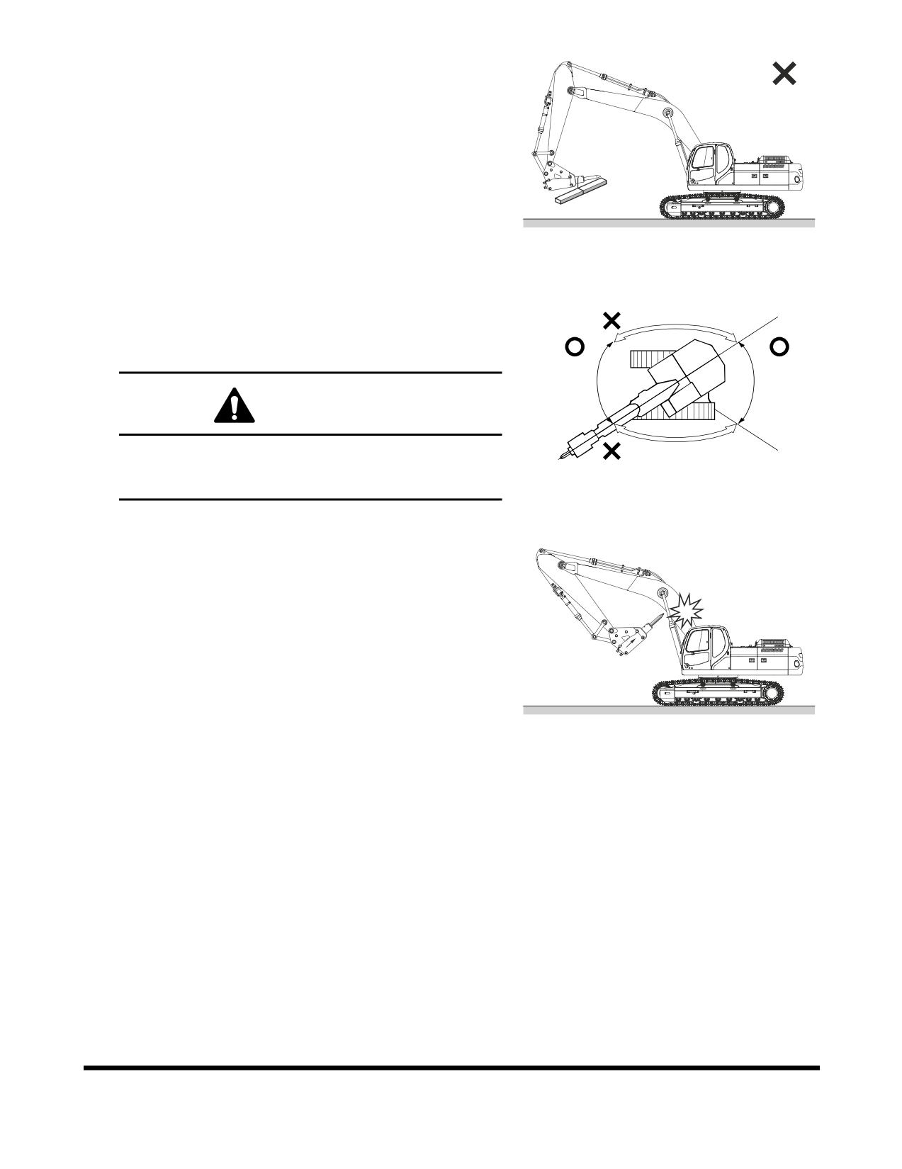
7.
Do not any lifting or towing with a breaker. See Figure
76.
FG006936
Figure 76
8.
Operate the breaker only to the front and rear of the
excavator. Do not use the breaker to either side of the
excavator. Do not swing the breaker from side to side
when operating it. See Figure 77.
WARNING!
Operating a breaker with the upper body turned 90° to
the tracks can result in tipping over the machine or
reduction in service life.
HAOB990L
Figure 77
9.
Do not curl the breaker tool tip into the arm or boom
when traveling or parking the excavator. See Figure 78.
FG006940
Figure 78
OP000483
Operation
3-35
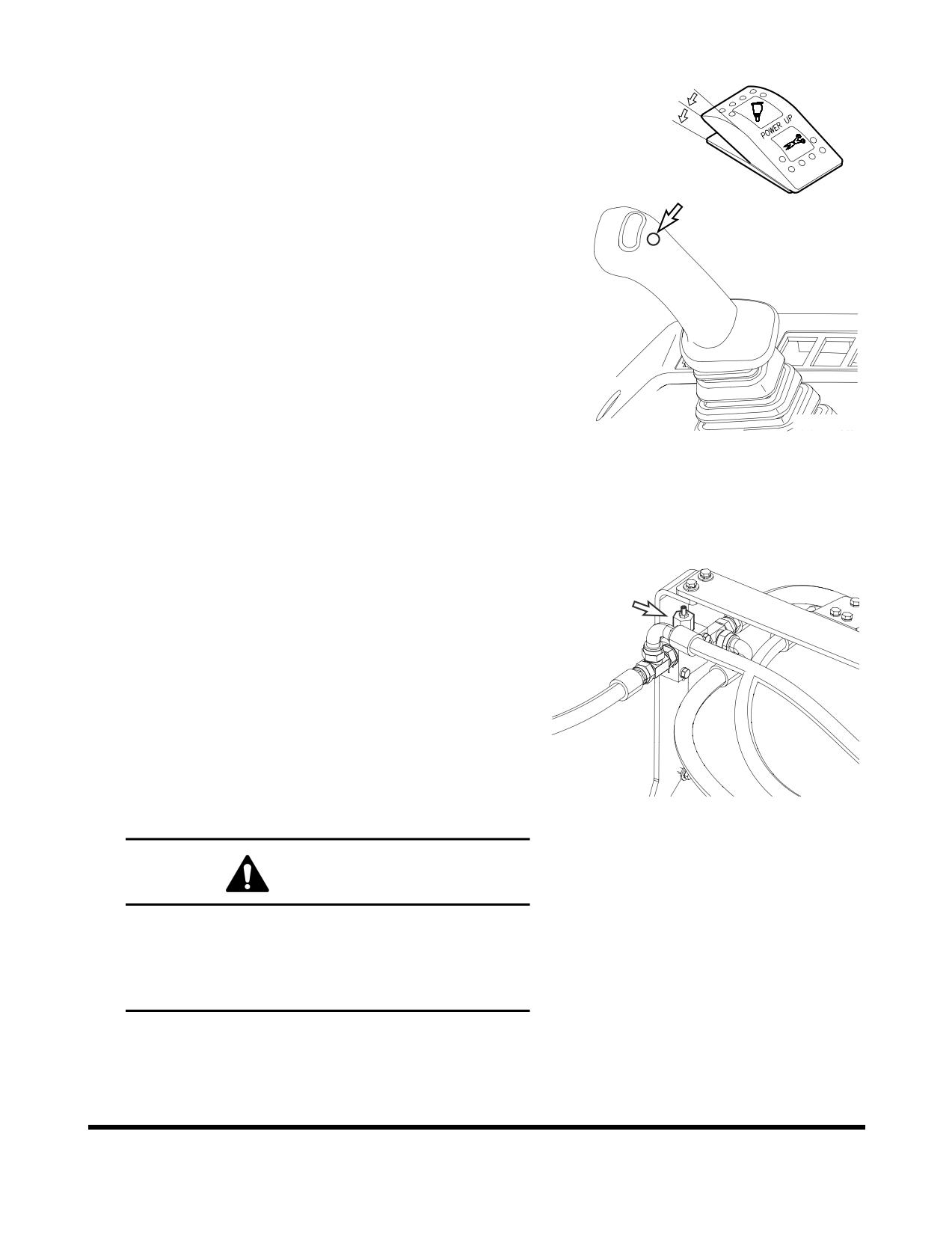
To activate breaker
I
1.
Set breaker selector switch to "II" (BREAKER) position.
O
2.
Press lower button on top of right-hand work lever
I
(joystick) to activate hydraulic breaker.
3.
Release lower button on top of right-hand work lever
(joystick) to deactivate hydraulic breaker.
FG000117
Figure 79 RIGHT-HAND WORK LEVER
(JOYSTICK)
Relief Valve Adjustment
1.
Cap pipe on arm end, using a cap capable of handling
350.0 kg/cm2
(5,000 psi) under the condition of
disconnecting hose to hydraulic breaker.
2.
Adjust pump pressure using activating the breaker, and
watching the pressure displayed on the instrument
panel. Press the display selector button to show digital
pressure reading. (A separate pressure gauge is not
required.)
3.
Adjust the relief valve pressure by turning the
adjustment screw of breaker relief valve. The relief
valve is installed on the left side of the upper structure
behind the boom. (Do not use the overload relief valve
FG006937
on the lower part of control valve for the breaker relief
Figure 80
valve.)
WARNING!
If the relief valve pressure is adjusted while the
hydraulic breaker is connected, there is possibility
that a high-pressure spike or setting could break a
hose or pipe. Personal injury or death could result
from a hydraulic hose or pipe failure.
Operation
OP000483
3-36
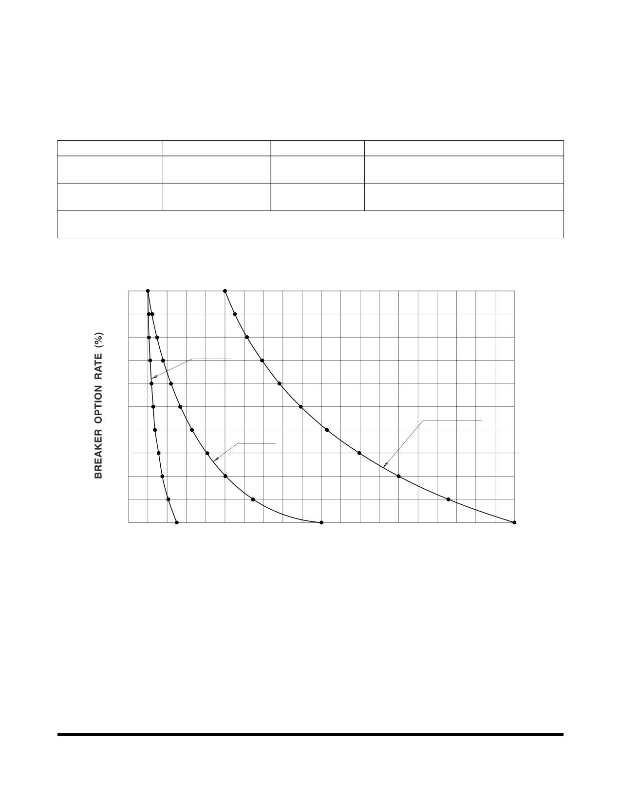
Hydraulic Oil and Filter Service Intervals
When using a hydraulic breaker, the viscosity breakdown
and contamination of hydraulic oil is faster because the work
condition is more severe than during normal digging work.
To prevent the hydraulic components (especially pump) from
having a shortened life cycle, replace the hydraulic oil and
main hydraulic oil return filter using the following schedule.
Attachment
Operation Rate
Hydraulic Oil
Filter
250 Hours (First Replacement)
Bucket Work
100%
2,000 Hours
1,000 Hours (After First Replacement)
Hydraulic Breaker
100%
500 Hours
100 Hours
Work
*
These service intervals only apply, when a genuine DOOSAN oil and filter are used. If any other
brands are used, the guaranteed changed interval should be reduced in half.
100
105
116
551
106
14
4
614
80
FILT
ER
692
112
171
(Firs
t Replacement)
119
214
782
60
128
275
893
HYDRAU
LIC OIL
137
335
1028
40
FILTER
15
6
412
(A
fter F
irst Replacement)
1196
175
500
1400
20
206
63
5
1658
0
500
1000
1500
2000
MACHINE OPERATING HOURS
FG000767
Figure 81
NOTE:
The replacement intervals of hydraulic oil and filter
depend upon the amount of time the hydraulic
breaker is being used. These intervals should be
followed as opposed to regularly scheduled
maintenance.
OP000483
Operation
3-37
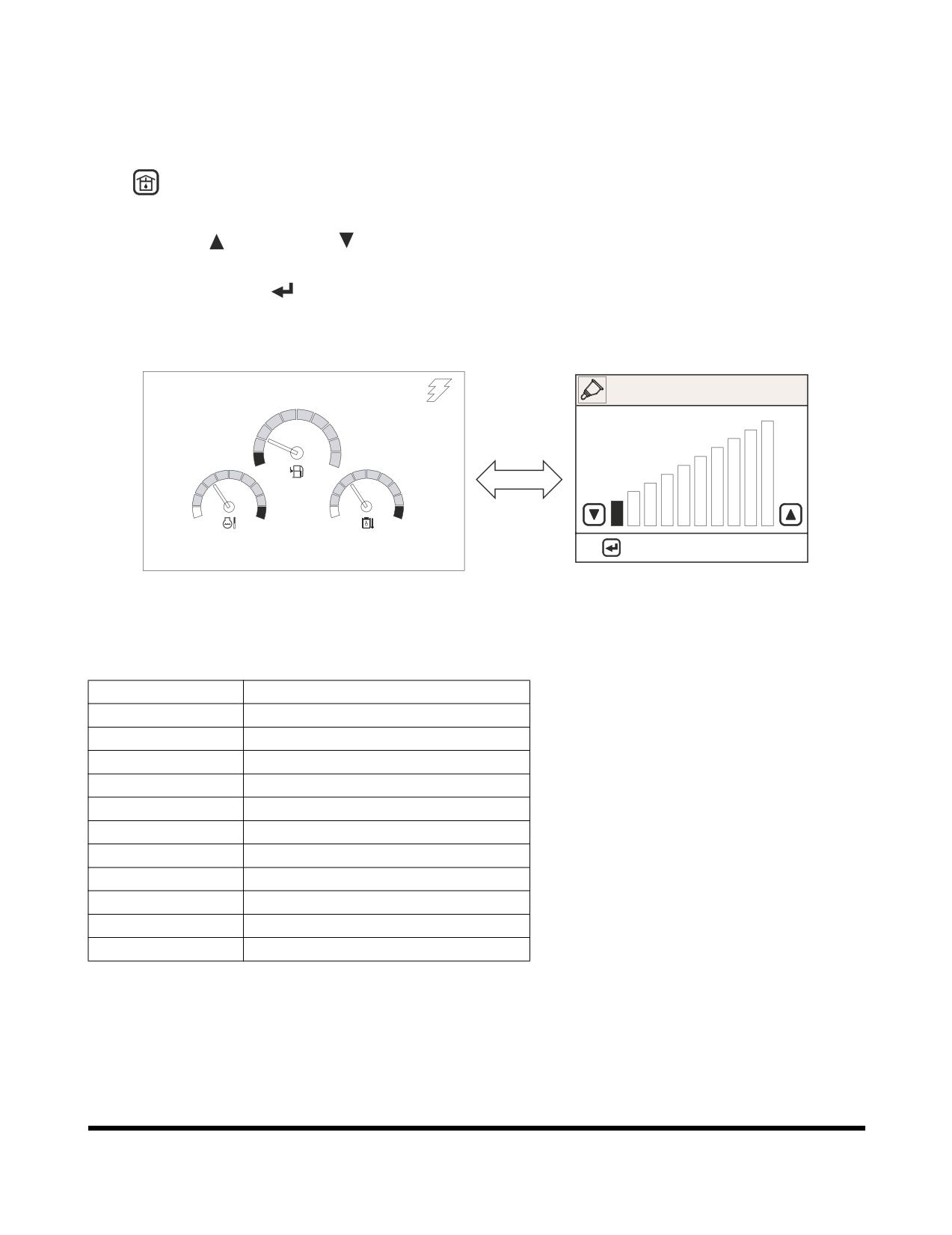
ADJUSTING THE PUMP FLOW
NOTE:
For further information, see “Flow Control” on
page 2-46.
1.
On the instrument panel, press the flow control button
, the flow control screen (Figure
82) will be
displayed.
2.
Use "UP" (
) or "DOWN" (
) buttons to adjust flow
rate.
3.
Press "SELECT"
(
) button, to return to normal
display screen and save the flow rate setting.
02/05 [MO] 11:30
FLOW CONTROL
E
F
C
H
C
H
: APPLY
ESC: CANCEL
E/G SPEED 1700 RPM
<Normal Display>
<Flow Control Display>
FG001090
Figure 82
Setting
Flow Rate (l/min)
0
48
1
53
2
71
3
89
4
109
5
128
6
148
7
167
8
187
9
207
10
219
Operation
OP000483
3-38
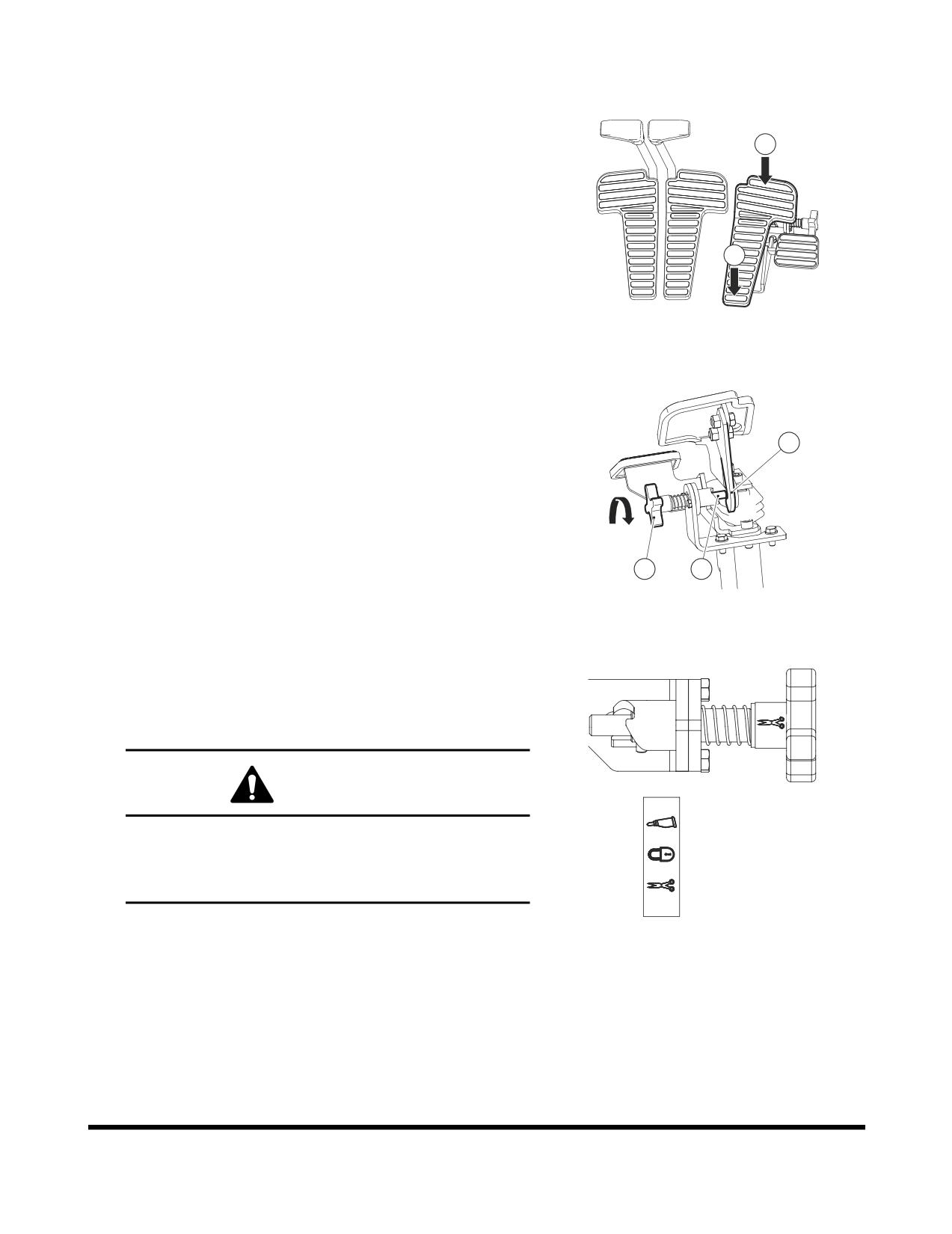
Shear Pedal Valve (Optional)
Activating Shear with Pedal Valve
1.
Select shear with the selector switch of the right panel.
1
2.
Two-way operation is possible by rocking the pedal
back and forth between positions (1 and 2, Figure 83).
When the pedal is in its center (at rest) position the
valve is in "NEUTRAL" and hydraulic oil flow is
stopped.
2
3.
Before operating the attachment, be sure to check the
function controlled by the direction of the pedal
movement.
FG000402
Figure 83
Activating Breaker with Pedal Valve
1.
Select breaker with the selector switch of the right
panel.
5
2.
Rotate knob (3, Figure 84) 120° for stopper (4, Figure
84) be fastened to (5, Figure 84).
3.
In the condition that (2, Figure 84) is fastened, activate
the breaker to the direction (1, Figure 84).
3
4
FG000403
Figure 84
Adjusting the Stopper
1.
Rotate knob
(3, Figure
84) in the direction of the
arrow. then the pedal is activated according to the
display caused by (3, Figure 84) knob rotation.
CAUTION!
Breaker
When operating breaker or shear when using button
on a joystick, and it is not to be controlled by the
Lock
pedal, be sure to keep the stopper in the "LOCK"
position in order for the pedal not to be activated.
Shear
FG000434
Figure 85
OP000483
Operation
3-39
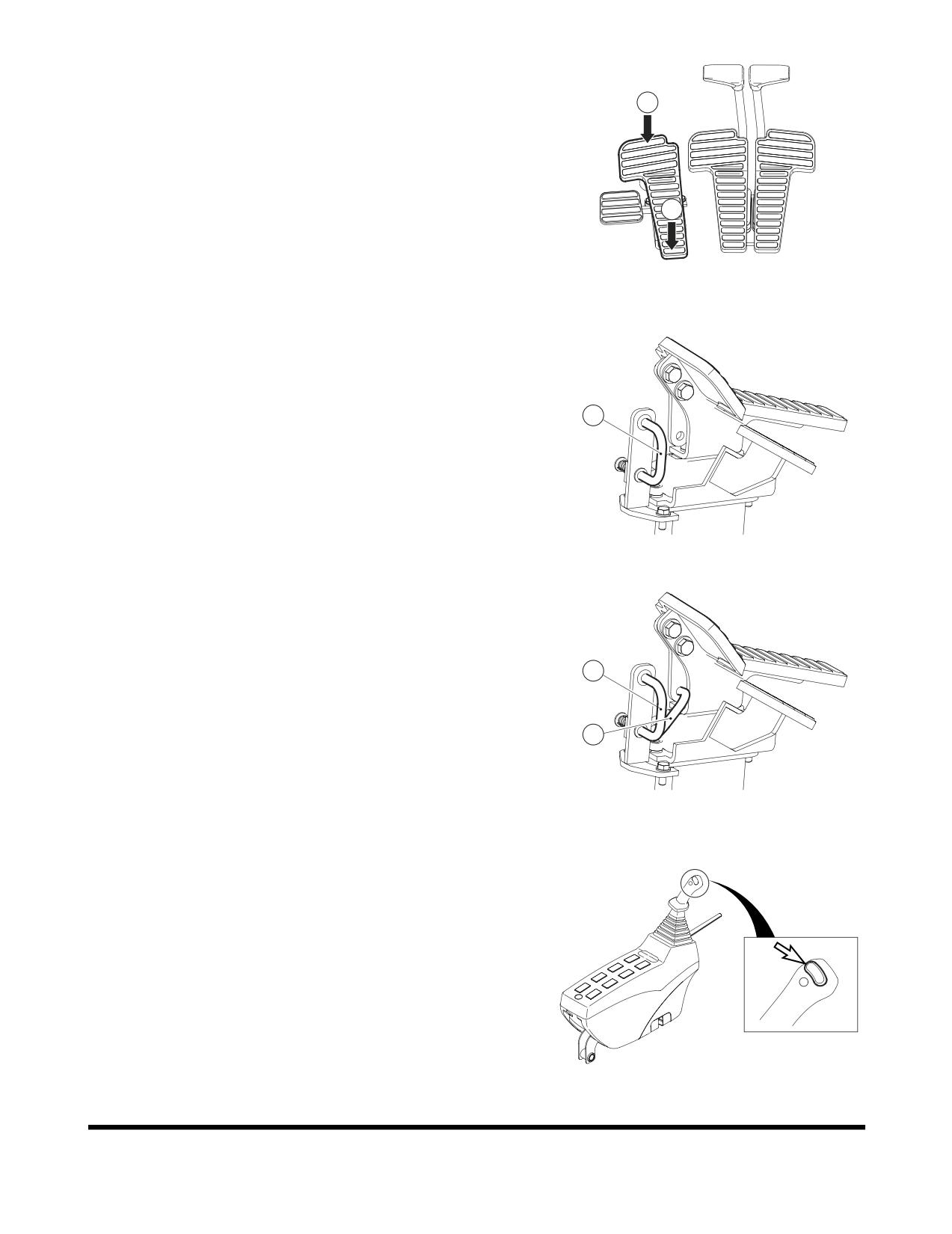
Rotating Pedal Valve (Optional)
1
Attachment Rotating by Using the Pedal Valve
1.
Pressing end (1, Figure 86) is used to turn clockwise.
2.
Pressing end
(2, Figure
86) is used to turn
counterclockwise.
2
NOTE:
Before activating the pedal, be sure to check
the function of the attachment.
FG000405
Figure 86
Locking the Pedal
When rotating is not needed, the pedal can be locked by
using the prop rod (3) locking device.
Locking is completed when the top end of the prop (3) is
3
positioned into pedal hole.
FG000406
Figure 87
A.
Location for "UNLOCKING."
B,
Location for "LOCKING."
A
B
FG000407
Figure 88
Attachment Rotation Using the Left-hand Work Lever
(Joystick)
For a machine equipped with an attachment that rotates,
rotation is activated while one of the control buttons is being
pressed on top of the left-hand work lever (joystick).
There are three buttons on top of the left-hand work lever.
The left and right ones are for controlling rotation.
NOTE:The middle button is for the horn.
Left button is for counterclockwise rotation, and the right one
FG000035
is for clockwise rotation.
Figure 89 LEFT-HAND WORK LEVER
(JOYSTICK)
Operation
OP000483
3-40
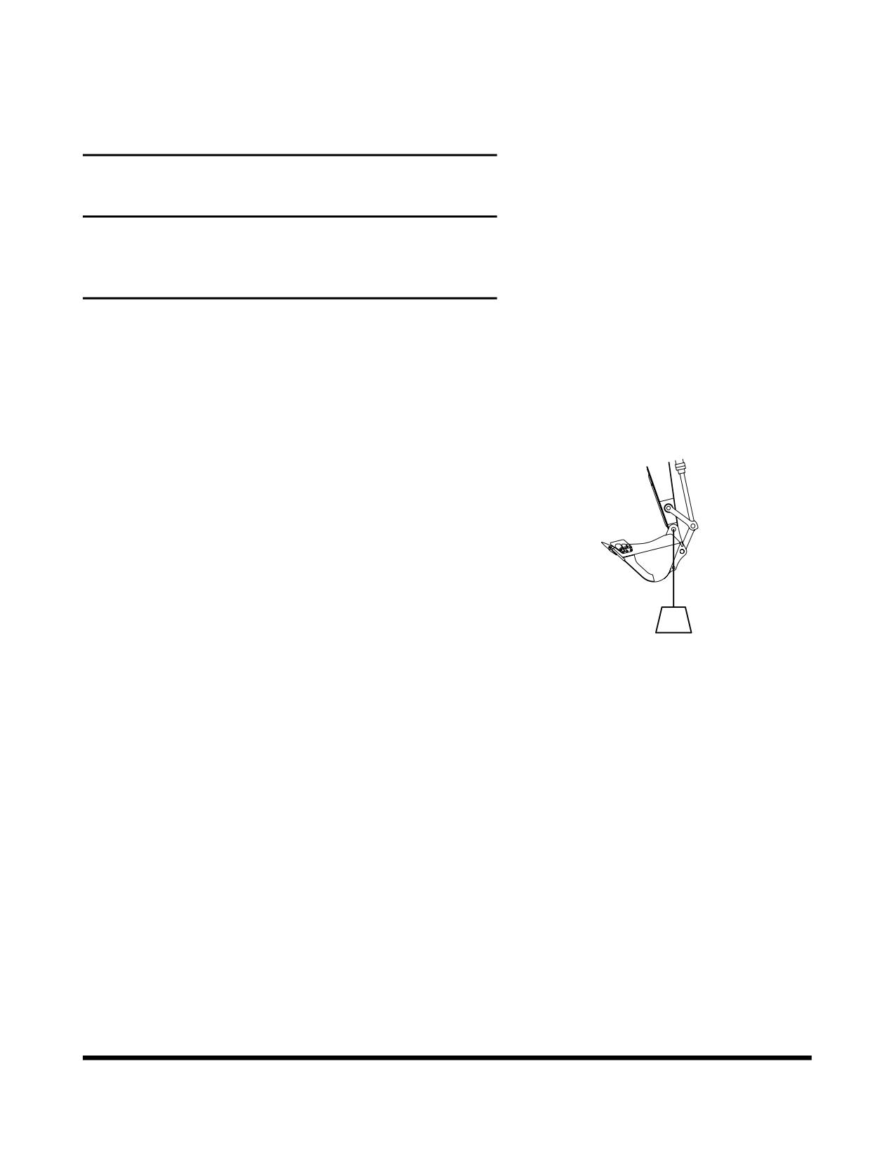
OPERATING TECHNIQUES
Lifting
IMPORTANT
There may be local or government regulations, about the
use of excavators for the lifting of heavy loads. Always
contact your local and government agencies in regards to
these regulations.
To prevent injury, do not exceed the rated load capacity of
the machine. If the machine is not on level ground, load
capacities will vary.
Short slings will prevent excessive load swing.
Use the lifting eye on the bucket that is provided to lift
objects.
Always try to maintain the lifting eye (Figure
90) straight
below the center line of the arm and bucket pin. In this
manner the weight of the load is being primarily held only
by the pin, and not by the bucket cylinder, link, and link
pins.
When a lifting eye is used, the sling/lifting device must be
fastened to the eye in a manner that will not allow it to
come loose.
The most stable position is over the corner of the machine.
For best stability, carry a load as close to the ground and
HAAD3830
machine as possible.
Figure 90
Lift capacity decreases as the distance from the machine
swing center line is increased.
OP000483
Operation
3-41
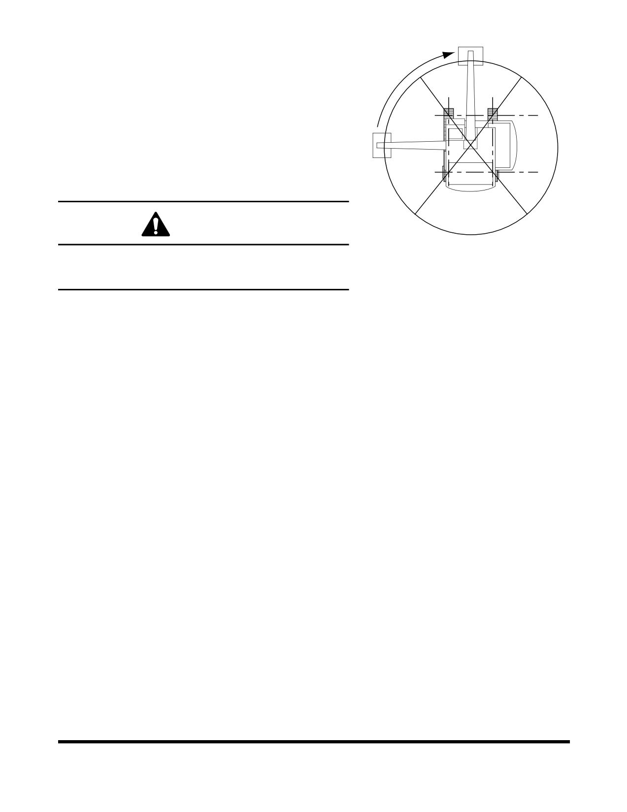
Lifting Unknown Weight
When loads are not accurately known are to be lifted, the
person responsible for the job shall ascertain that the weight
FRON
T LIFT
of the load does not exceed the machine LOAD RATING
ZO
N
E
CHART at the radius at which it is to be lifted.
It is recommended that you feel your way into any lift as a
precaution against tip-over. One method is to position the
boom at 90° over the side of the machine. Slowly lift the
SIDE LIFT
SIDE LIFT
ZONE
ZONE
load until it clears the ground. A lift over the side is the
most unstable, and as the load is swung into the front zone
of the excavator it will become more stable. DO NOT
INCREASE SWING RADIUS AFTER THE LOAD IS LIFTED.
REAR LIFT
ZONE
DANGER!
HAAD3842
Figure 91
If a load is picked up from the front zone and swung into the
side zone, a tip-over could result causing a deadly or fatal
injury.
Lifting Known Weight
The load chart is the governing factor when lifting known
weights. It is recommended that you feel your way into any
lift as a precaution against tip-over. Whenever possible, lift
and swing payloads between the front idler area.
Pick and Carry
The machine has the ability to pick and carry payloads
without added labor. We recommend when traveling with a
suspended payload, you evaluate the prevailing conditions
and determine the safety precautions required in each case.
The following factors must be considered before attempting
to pick and carry a load.
Align the boom with the forward direction of machine travel.
Maintain this boom position when turning the machine. Turn
only when necessary, at the slowest speed, and at a wide
turning radius.
1.
Use the shortest lifting radius distance possible.
2.
Keep the load as close to the ground as conditions will
permit.
3.
Provide tag lines to prevent load from pendulating.
Pendulating can cause a change in radius. A change in
radius could exceed the load chart rating or cause a
tip-over condition.
4.
Govern travel speed to suit conditions.
5.
Avoid sudden starts and stops.
Operation
OP000483
3-42