Doosan DX255LC. Operation and Maintenance Manual (2006) - page 4
OPERATION UNDER UNUSUAL
CONDITIONS
NOTE:
See “Maintenance in Special Conditions” on
page 4-86 for other recommendations.
Operation In Extreme Cold
If machine is to be operated in extreme cold weather
temperatures, certain precautions must be taken to assure
continued normal operation. The following paragraphs detail
checks to be made to be certain the machine is capable of
operating at these temperatures.
1.
Check the cooling system for correct antifreeze solution
for lowest temperature expected. Carefully inspect
cooling system and correct or report any leaks.
2.
Keep batteries fully charged to prevent freezing. If
water is added to batteries, run engine at least one
hour to mix electrolyte solution.
3.
Keep engine in best possible mechanical condition to
assure easy starting and good performance during
adverse weather conditions.
4.
Use engine oil of the proper specifications for the
expected temperatures. Refer to the "Lubrication
Specifications" of the engine manual for details.
5.
Keep fuel tank full at all times. Drain condensation
from tank before and after operation. Drain and service
fuel filter. To eliminate clogging of fuel filters due to
wax crystal formation in the fuel, be sure that the fuel
used has a cloud point specification below the lowest
expected temperature.
6.
Lubricate entire machine according to "Periodic Service
Table and Chart" Section
4, in this manual or
lubrication chart on machine.
7.
Start engine and allow it to reach normal operating
temperature before applying load.
A.
If mud and ice collects and freezes on any of the
moving parts while machine is idle, apply heat to
thaw the frozen material before attempting to
operate machine.
B.
Operate hydraulic units with care until they have
reached a temperature to enable them to operate
normally.
C.
Check all machine controls and/or functions to be
sure they are operating correctly.
8.
An extra outer air filter should be kept in the operator's
cabin to replace element that could become iced and
cause restricted air flow to engine.
OP000483
Operation
3-43
9.
If cold weather starting aid must be used, see "Engine
Starting" COLD WEATHER START portion of this manual.
10. Clean off all mud, snow and ice to prevent freezing.
Cover machine with tarpaulin if possible, keep ends of
tarpaulin from freezing to ground.
Operation in Extreme Heat
Continuous operation of the machine in high temperatures
may cause the machine to overheat. Monitor engine and
transmission temperatures and stop machine for a cooling-off
period whenever necessary.
1.
Make frequent inspections and services of the fan and
radiator. Check coolant level in radiator. Check grills
and radiator fins for accumulation of dust, sand and
insects which could block the cooling passages.
A.
Formation of scale and rust in cooling system
occurs
more rapidly in extremely
high
temperatures. Change antifreeze each year to
keep corrosion inhibitor at full strength.
B.
If necessary, flush cooling system periodically to
keep passage clear. Avoid use of water with a
high alkali content which increases scale and rust
formation.
2.
Check level of battery electrolyte daily. Keep electrolyte
above plates preventing damage to batteries. Use a
slightly weaker electrolyte solution in hot climates.
Dilute 1.28 specific gravity electrolyte as issued to 1.20
- 1.24 specific gravity readings at full charge. Recharge
batteries whenever they reach a 1.16 specific gravity
reading. Batteries self-discharge at a higher rate if left
standing for long periods at high temperatures. If
machine is to stand for several days, remove batteries
and store in a cool place.
WARNING!
Do not store acid type storage batteries near stacks of
tires; the acid fumes have a harmful affect on rubber.
3.
Service fuel system as directed in "Engine Fuel
System" Section
5, of this manual. Check for water
content before filling fuel tank. High temperatures and
cooling off cause condensation in storage drums.
4.
Lubricate as specified in "Periodic Service Chart and
Table" Section 4, in this manual or Lubrication Decal
on the machine.
5.
Do not park machine in sun for long periods of time.
When practical park machine under cover to protect it
from sun, dirt and dust.
Operation
OP000483
3-44
A.
Cover inactive machine with tarpaulin if no suitable
shelter is available. Protect engine compartment,
transmission and hydraulics from entrance of dust.
B.
In hot, damp, climates corrosive action will occur
on all parts of the machine and will be accelerated
during the rainy season. Rust and paint blisters will
appear on metal surfaces and fungus growth on
other surfaces.
C.
Protect all unfinished, exposed surfaces with a
film of preservative lubricating oil. Protect cables
and terminals with ignition insulation compound.
Apply paint or suitable rust preventive to damaged
surfaces to protect them from rust and corrosion.
Operation in Dusty or Sandy Areas
Operation of the machine can cause dust in almost any
area. However, when in predominantly dusty or sandy areas,
additional precautions must be taken.
1.
Keep cooling system fins and cooling areas clean. Blow
out with compressed air, if possible, as often as necessary.
WARNING!
Wear goggles when using compressed air.
2.
Use care when servicing fuel system to prevent dust
and sand from entering the tank.
3.
Service the air cleaner at frequent intervals, check air
restriction indicator daily and keep dust cup and dust
valve clean. Prevent dust and sand from entering
engine parts and compartments as much as possible.
4.
Lubricate and perform services outlined on current
lubrication chart on machine and "Lubrication Chart and
Table" Section
4. Clean all lubrication fittings before
applying lubricant. Sand mixed with lubricant becomes
very abrasive and speeds wear on parts.
5.
Protect machine from dust and sand as much as
possible. Park machine under cover or protect with
tarpaulin to keep dust and sand from damaging unit.
Operation in Rainy or Humid Conditions
Operation under rainy conditions is similar to that as in
extreme heat procedures listed previously.
1.
Keep all exposed surfaces coated with preservative
lubricating oil. Pay particular attention to damaged or
unpainted surfaces. Cover all paint cracks and chip
marks as soon as possible to prevent corrosive effects.
OP000483
Operation
3-45
Operation in Salt Water Areas
The corrosive effect of salt water and salt water spray is
very extensive. When operating in salt water areas, observe
the following precautions.
1.
When exposed to salt water, dry machine thoroughly
and rinse with fresh water as soon as possible.
2.
Keep all exposed surfaces coated with preservative
lubricating oil. Pay particular attention to damaged paint
surfaces.
3.
Keep all painted surfaces in good repair.
4.
Lubricate machine as prescribed on lubrication chart on
machine or "Periodic Service Table and Chart" Section
4, in this manual. Shorten lubricating intervals for parts
subject to exposure to salt water, if found necessary.
Operation at High Altitudes
Normally, operation of machine at high altitudes will be as
outlined in extreme cold. Before operating at high altitudes,
engine fuel and air mixture may have to be adjusted
according to appropriate engine manual.
1.
Check engine operating temperature for evidence of
overheating. The pressure cap on radiator must make
a perfect seal to maintain coolant pressure in the
system.
Operation
OP000483
3-46
OP000484
4Inspection, Maintenance
and Adjustment
PREVENTIVE MAINTENANCE
Routine maintenance and inspections are required to keep
your machine in the correct operating condition. The
following pages list the inspection intervals, the system or
component checks, and location references.
NOTE:
The following pages list the service checks and their
required intervals. The service cycles may need to be
shortened depending on the working conditions.
Extremely hot or dusty conditions will require more
frequent service. Operational hours are determined
by the amount of time accumulated on the engine
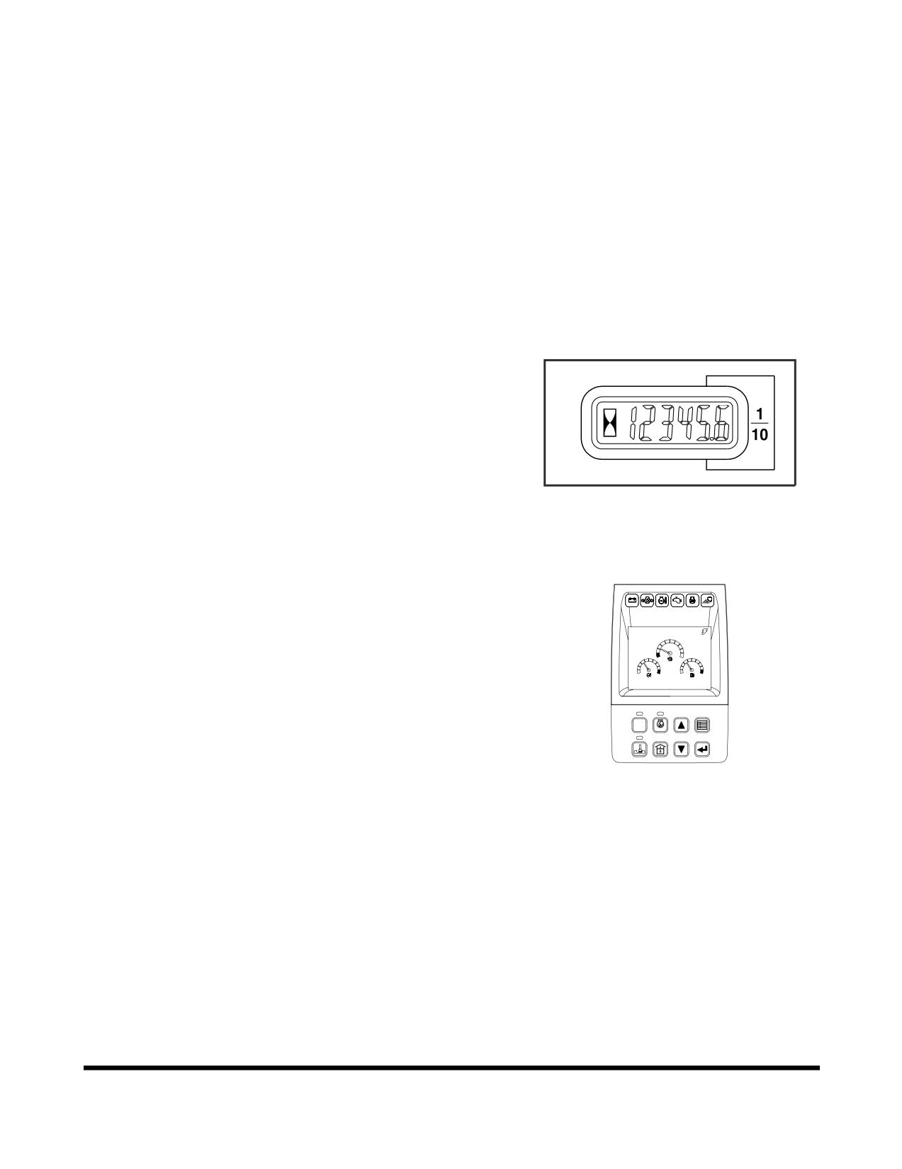
hour meter on the control console in the cabin.
HAOA601L
Figure 1
NOTE:
Besides the normal hour meter, the multifunction
gauge can be used to keep track of the hours on
CHECK
individual filters. See “Filter / Oil Info” on page 2-40.
02/05 [MO] 11:30
E
F
C
H
C
H
E/G SPEED
1700
RPM
POWER
AUTO
1
2
3
4
ESC
5
6
7
8
FG000037
Figure 2
OP000484
Inspection, Maintenance and Adjustment
4-1
Product Identification Number (P. I. N.)
Location
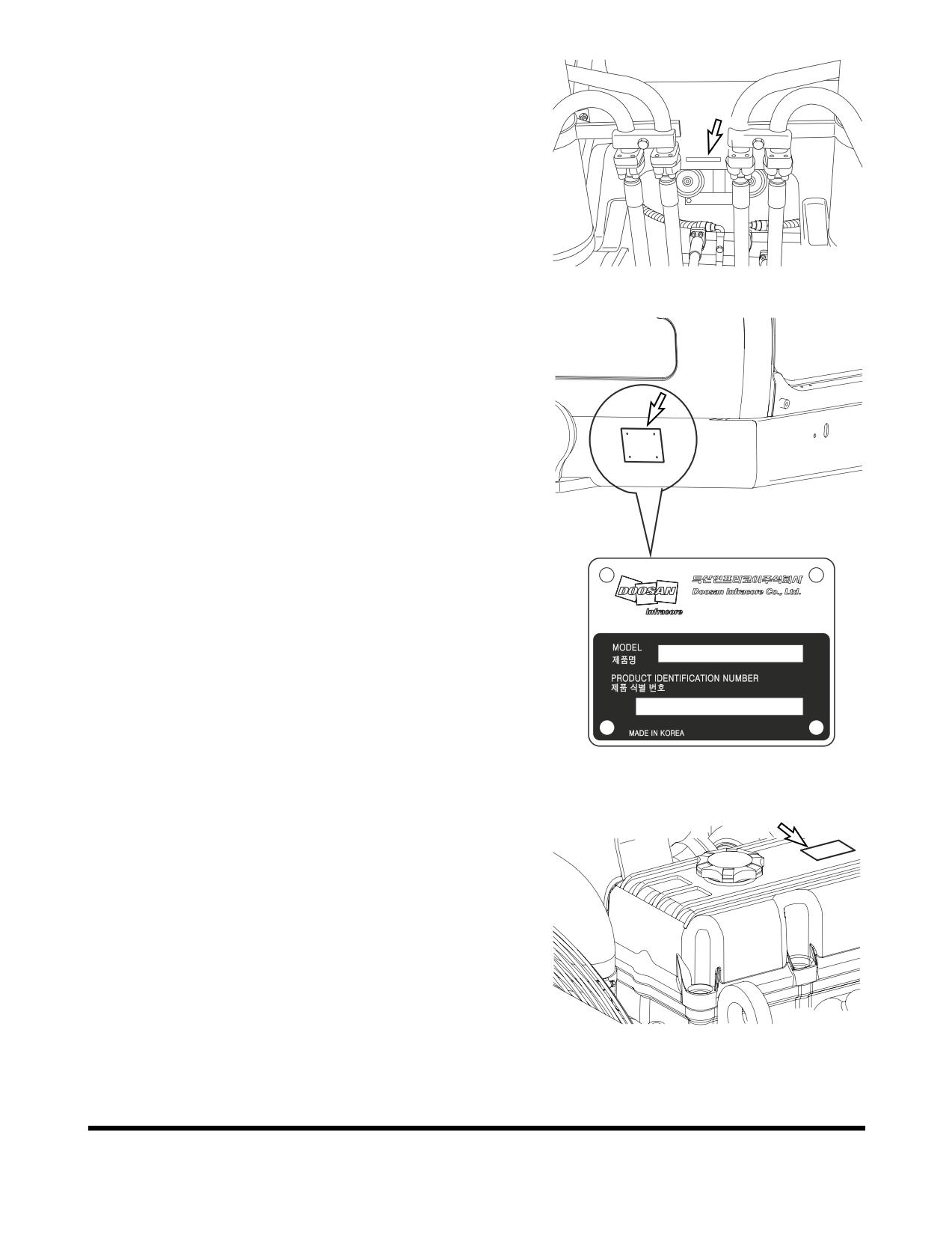
A P.I.N. number, is stamped on the upper frame, under the
boom foot (Figure
3). It is also stamped on the product
identification plate (Figure
4) on outside of the cabin on
right.
NOTE:
Please make note of these numbers and their
locations. These will be required whenever warranty
or service work is requested. Keep this number on
FG001447
file, incase the machine is stolen.
Figure 3
7-11, Hwasu-dong, Dong-gu,
Incheon, Korea
K1011647A
FG000764
Figure 4
Component Serial Numbers
There are many serial numbers on each traceable
components of the machine. For example, the engine serial
number is stamped on the rear left side of the engine block,
above the starter. Additional engine information is described
on a label (Figure 5) on the rocker cover.
Please make note of these numbers and their locations.
These will be required whenever warranty service work is
requested.
FG000664
Figure 5
Inspection, Maintenance and Adjustment
OP000484
4-2
Safety Precautions
1.
Make sure to lock out the hydraulic controls and post a
notice (Warning Tag) that the machine is being
serviced to prevent any unauthorized operation.
2.
Make sure to clean up any fluid spills, especially
around the engine.
3.
Inspect all fuel lines to make sure that fittings, lines,
filters and O-rings, etc., are tight and are not showing
signs of wear or damage.
4.
If the inspection or test procedure requires that the
engine be running, make sure to keep all unauthorized
personnel away from the machine, and that all industry
standard safety precautions are followed.
OP000484
Inspection, Maintenance and Adjustment
4-3
PRELIMINARY WORK MACHINE
SETUP FOR MAINTENANCE
When performing maintenance specified in this manual,
always park the excavator as follows.
NOTE:
Certain types of maintenance may require the
machine to be positioned differently. Always return
machine to this position.
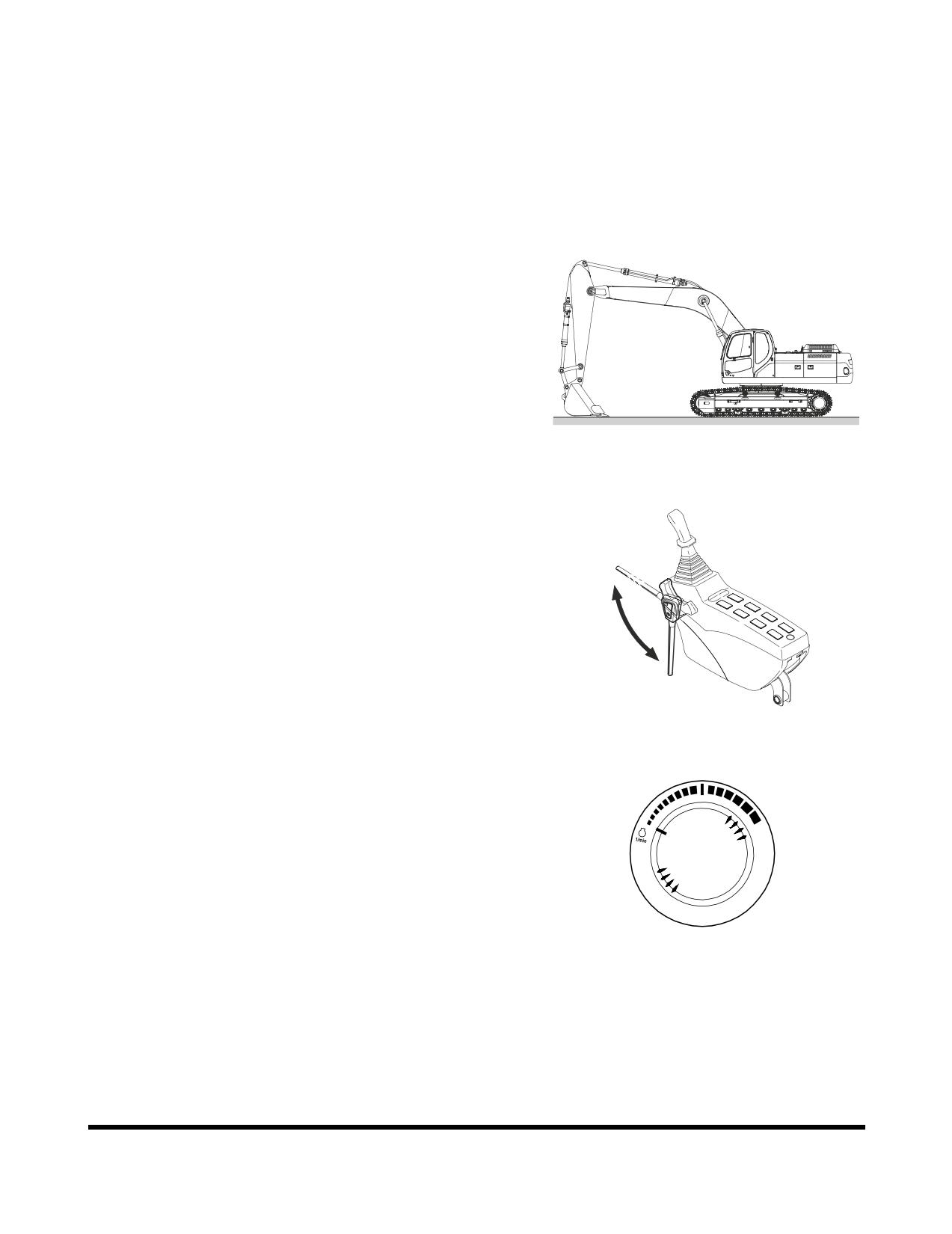
1.
Park on firm, level ground.
2.
Lower bucket to ground.
FG006932
Figure 6
3.
Set safety lever on "LOCK" position.
Unlock
lock
FG001091
Figure 7
4.
Allow engine to run at low idle for a minimum of five
minutes to allow engine to cool. If this is not done,
heat surge may occur.
HAOB290L
Figure 8
Inspection, Maintenance and Adjustment
OP000484
4-4
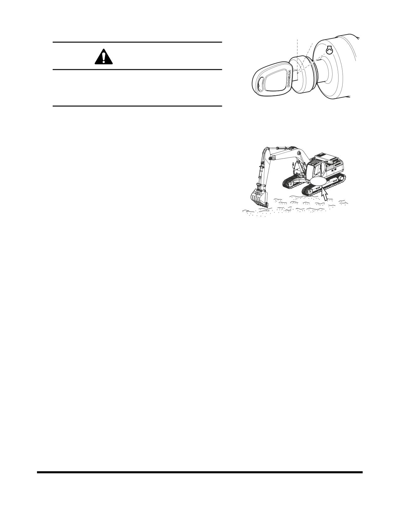
5.
Shut down engine by turning key to "O" (OFF) position.
Remove key from starter switch.
O I
WARNING!
If
engine must be run while performing
maintenance, use extreme care. Always have one
person in the cabin at all times. Never leave the
cabin with the engine running.
FG000175
Figure 9
6.
Before starting maintenance work, hang up a tag, "Do
Not Touch When Performing Inspection or
Maintenance" on cabin door or work lever.
FG000401
Figure 10
OP000484
Inspection, Maintenance and Adjustment
4-5
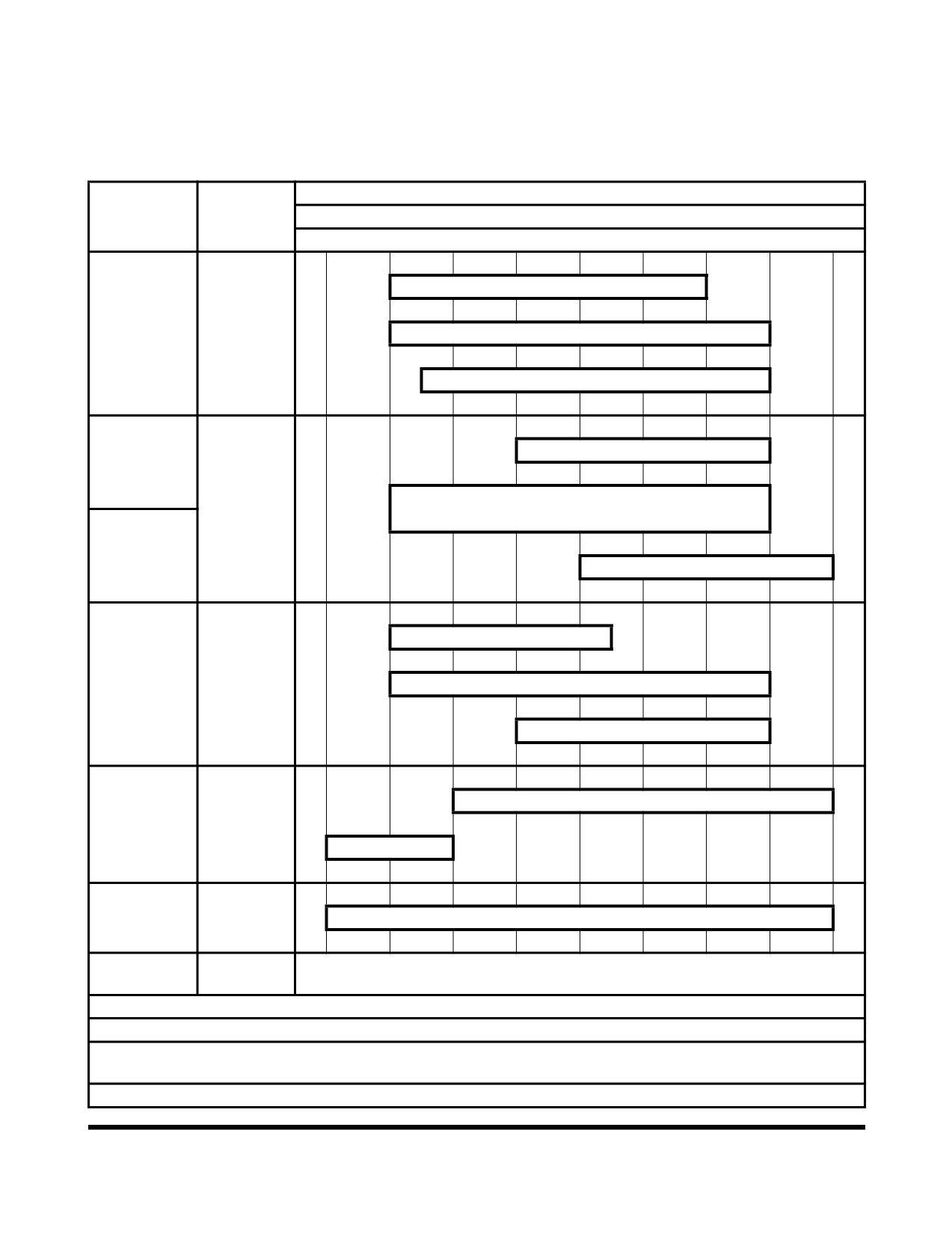
TABLE OF RECOMMENDED
LUBRICANTS
NOTE:
Refer to the Maintenance Intervals Table for
application points.
Ambient Temperature
Kind of
Reservoir
-22
-4
14
32
50
68
86
104
122 °F
Fluid
-30
-20
-10
0
10
20
30
40
50 °C
SAE 10W-30
Engine Oil
**
* SAE 10W-40
Pan
Engine Oil
SAE 15W-40
Swing Drive
SAE 90 and API GL5
Case
Gear Oil
* SAE 80W-90 and API GL5
Final Drive
Case
SAE 140 and API GL5
ISO VG 32
***
Hydraulic
Hydraulic
* ISO VG 46
Oil Tank
Oil
ISO VG 68
* ASTM D975 No. 2
Diesel
Fuel Tank
Fuel
ASTM D975 No. 1
Grease
Grease
* Multipurpose Lithium Grease NLGI No. 2
Fitting
Cooling
Add Antifreeze
Coolant
System
* (50% antifreeze - 50% distilled water)
*
Installed at factory.
**
Engine oil must meet ACEA-E5 or API-CI-4.
*** Hydraulic oil change interval is 2,000 hours, only when DOOSAN Genuine Oil is used. If other
brands of oil is used, guaranteed change interval is 1,000 hours.
API: American Petroleum Institute.
Inspection, Maintenance and Adjustment
OP000484
4-6
ACEA: Association des Constructeurs Europens d’Automobiles.
ASTM: American Society of Testing and Material.
ISO: International Standardization Organization.
NLGI: National Lubricating Grease Institute.
SAE: Society of Automotive Engineers.
IMPORTANT
Do not mix oils from different manufacturers. DOOSAN
does not endorse specific brands but does suggest that
owners select quality oils whose suppliers provide
assurance that required standards will always be met or
exceeded.
Fluctuating daily or weekly extremes of temperature, or
operation in subzero freezing weather may make it
impractical to use straight weight lubricants. Use good
judgement in selecting lubricant types that are
appropriate for climate conditions.
OP000484
Inspection, Maintenance and Adjustment
4-7
FLUID CAPACITIES
Component
Capacity
Engine
Oil Pan with Filter
27 liters
(7.1 U.S. gal.)
Cooling System
24 liters
(6.3 U.S. gal.)
Fuel Tank
410 liters
(108 U.S. gal.)
Hydraulic Oil
Tank Level
150 liters
(40 U.S. gal.)
System
240 liters
(63 U.S. gal.)
Travel Reduction Device (Each)
3.3 liters
(0.87 U.S. gal.)
Swing Device
7.3 liters
(1.93 U.S. gal.)
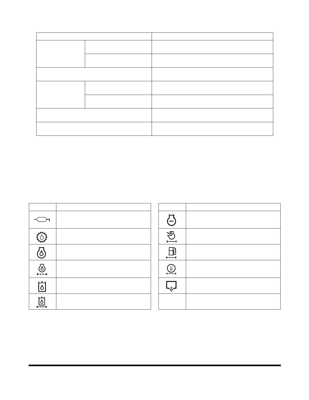
LUBRICATION AND SERVICE
CHART
Lubrication and service chart is on the inside of battery box
cover. The symbols shown here are used in the lubrication
and service chart on the next page.
Symbol
Description
Symbol
Description
Lubrication
Coolant
Gear Oil (Swing Device, Travel Device)
Air Cleaner Element
Engine Oil
Fuel Filter
Engine Oil Filter
Air Conditioner Filter
Hydraulic Oil
Drain Water
Hydraulic Oil Return Filter
Inspection, Maintenance and Adjustment
OP000484
4-8
OP000484
Inspection, Maintenance and Adjustment
4-9
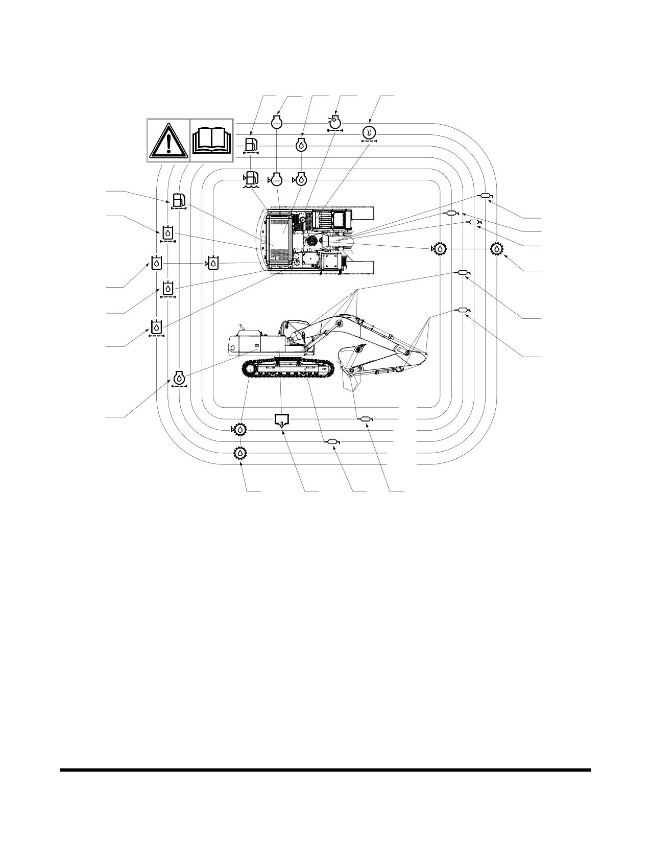
Description of Lubrication and Service Chart
12
13
9
19
20
18
14
5
3
4
6
10
15
2
16
2
10h
17
50h
250h
500h
1000h
2000h
8
11
7
1
FG008488
Figure 11
Inspection, Maintenance and Adjustment
OP000484
4-10
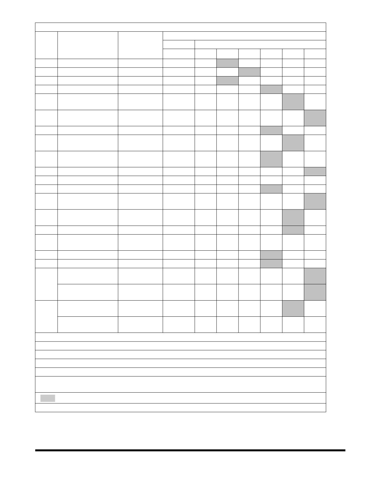
SERVICE DATA
DX255LC
No.
Items to Check
Service
Qty.
Service Interval
10
50
250
500
1000
2000
1
Front Joint Pin (1)
Grease
6
F100
W10
2
Front Joint Pin (2)
Grease
11
F100
W10
3
Swing Bearing
Grease
3
W10
4
Swing Gear
Grease
1
Swing Reduction
5
Grease
1
W10
Gear
Gear Oil
6
Swing Device
5 L
V
F
(80W90)
7
Track Spring
Grease
2
W10
Travel Reduction
Gear Oil
8
2X3.3 L
F, V
Device
(80W90)
Engine Oil
9
Engine Oil
27 L
V
F
(10W40)
10
Hydraulic Oil Tank
Hydraulic Oil
240 L
V
11
Fuel Tank
Diesel
410 L
V
12
Fuel Prefilter
Cartridge
1
V
Coolant
13
Radiator
30 L
V
PG
(Antifreeze)
Hydraulic Oil
14
Element
1
F
Return Filter
15
Pilot Filter
Element
1
F
Hydraulic Oil
16
Strainer
1
C
Suction Strainer
17
Engine Oil Filter
Cartridge
1
F
18
Fuel Filter
Cartridge
1
Air Cleaner
Element
1
C
(Outer)
19
Air Cleaner
Element
1
(Inner)
Air Conditioner
Cartridge
1
C
Filter (Outer)
20
Air Conditioner
Cartridge
1
C
Filter (Inner)
V: Maintenance and Refill.
C: Cleaning.
F: First Time Exchange Only.
F100: Every 10 Hours For First 100 Hours.
W10: Every 10 Hours If Operating In Water.
PG: Propylene Glycol - Extended Life Antifreeze (Drain and replace using this interval.) See
“Engine Cooling System” on page 4-75, for further explanation.
: Replacement On Every Interval.
NOTE:
For additional service items see list of “Maintenance Intervals” on page 4-12.
OP000484
Inspection, Maintenance and Adjustment
4-11
MAINTENANCE INTERVALS
SERVICE ITEM
PAGE
10 Hour / Daily Service
Grease Boom, Arm and Front Attachment Pins (for first 100 hours)
4-14
Check Engine Oil Level
4-14
Check Level of Hydraulic Oil Tank
4-15
Check for Leaks in Hydraulic System
4-16
Check Fuel Level
4-16
Check for Leaks in Fuel System
4-17
Check Fuel Prefilter and Drain Water As Required
4-18
Check Oil Level of Swing Reduction Device
4-19
Clean Dust Net in Front of Oil Cooler and Intercooler
4-20
Check Cooling System and Refill As Required
4-20
Check Level of Window Washer Liquid
4-21
Inspect the Bucket Teeth and Side Cutters for Signs of Wear
4-21
Inspect Cooling Fan Blade
4-22
Check Air Intake System
4-22
Inspect Seat Belt for Proper Operation
4-22
Inspect the Structure for Cracks and Faulty Welds
4-23
Check the Operation of All Switches
4-23
Check the Operation of All Exterior Lights, Horn and Control Console Indicator and
4-23
Monitor Lights
Start Engine, Check Starting Ability, and Observe Exhaust Color at Start-up and at
4-23
Normal Operating Temperature. Listen for Any Abnormal Sounds
Check Operation of All Controls
4-24
50 Hour / Weekly Service
Perform All Daily Service Checks
4-25
Grease Arm and Front Attachment Pins
4-25
Grease Swing Bearing
4-26
Drain Water and Sediment from Fuel Tank
4-27
Check Engine Fan Belt for Cracks, Wear and Correct Tension (After First 50 Hours)
4-27
Change Engine Oil and Filter (After First 50 Hours)
4-27
Inspect the Track Assemblies for Proper Tension and Loose, Worn or Damaged Parts
4-27
(Links, Shoes, Rollers, Idlers)
250 Hour / Monthly Service
Perform All Daily and 50 Hour Service Checks
4-28
Change Swing Reduction Device Oil (Drain and Refill After First 250 Hours)
4-28
Grease Arm and Front Attachment Pins
4-29
Check Engine Fan Belt Tension
4-31
Check Engine Fan Belt Wear
4-31
Check Oil Level in Travel Reduction Device (One on Each Side of Unit)
4-32
Change Breaker Filter Element (Optional)
4-33
Change Oil in Travel Reduction Device (One on Each Side of Unit) (After First 250 Hours)
4-33
Change Hydraulic Oil Return Filter (After First 250 Hours)
4-33
Change Pilot Filter (After First 250 Hours)
4-33
Inspection, Maintenance and Adjustment
OP000484
4-12
SERVICE ITEM
PAGE
Inspect Pins and Bushings of the Front End Attachments for Signs of Wear
4-34
Check Fluid Levels in Batteries and Battery Charge Levels
4-34
Inspect for Any Loose or Missing Nuts and Bolts
4-34
Inspect Fuel System Hose Clamps
4-34
500 Hour / 3 Month Service
Perform All Daily, 50 and 250 Hour Service Checks
4-35
Grease Swing Gear and Pinion
4-35
Change Engine Oil and Filter
4-36
Clean Air-Conditioning Outer Filter
4-37
Check and Clean Air-Conditioning Inner Filter
4-38
Clean Radiator, Oil Cooler, Intercooler, Fuel Cooler and Air Conditioner Condenser Core
4-39
Clean Outer Filter of Air Cleaner
4-40
Change of Fuel Prefilter
4-41
Change Fuel Filter
4-42
1,000 Hour / 6 Month service
Perform All Daily, 50, 250 and 500 Hour Service Checks
4-44
Grease Swing Reduction Device
4-44
Change Hydraulic Oil Return Filter
4-45
Change Pilot Filter
4-46
Change Oil in Travel Reduction Device (One on Each Side of Unit)
4-47
Change Air-Conditioning Outer Filter
4-48
Check Air Conditioner Refrigerant
4-49
Check and Adjust Engine **
4-50
2,000 Hour / Yearly Service
Perform All Daily, 50, 250, 500 and 1,000 Hour Service Checks
4-51
Change Swing Reduction Device Oil
4-51
Change Outer and Inner Air Cleaner Elements
4-52
Change Radiator Coolant
4-53
Hydraulic Oil Exchange and Suction Strainer Cleaning
4-54
Check Alternator and Starter**
4-56
Check All Rubber Antivibration Shock Mounts
4-56
Perform and Record the Results of the Cycle Time Tests
4-56
Inspect Machine to Check for Cracked or Broken Welds or other Structural Damage
4-56
Check, Adjust Valve Clearance **
4-56
Check Head Bolt Torques
4-56
4,000 Hour / Biennial Service
Major Parts - Periodic Replacement
4-57
12,000 HOUR / SIX YEAR SERVICE
Hose In-service Lifetime Limit (European Standard ISO 8331 and EN982 CEN)
4-58
** These checks need to be completed by an authorized DOOSAN dealer.
OP000484
Inspection, Maintenance and Adjustment
4-13
10 HOUR / DAILY SERVICE
Grease Boom, Arm and Front Attachment
Pins (for first 100 hours)
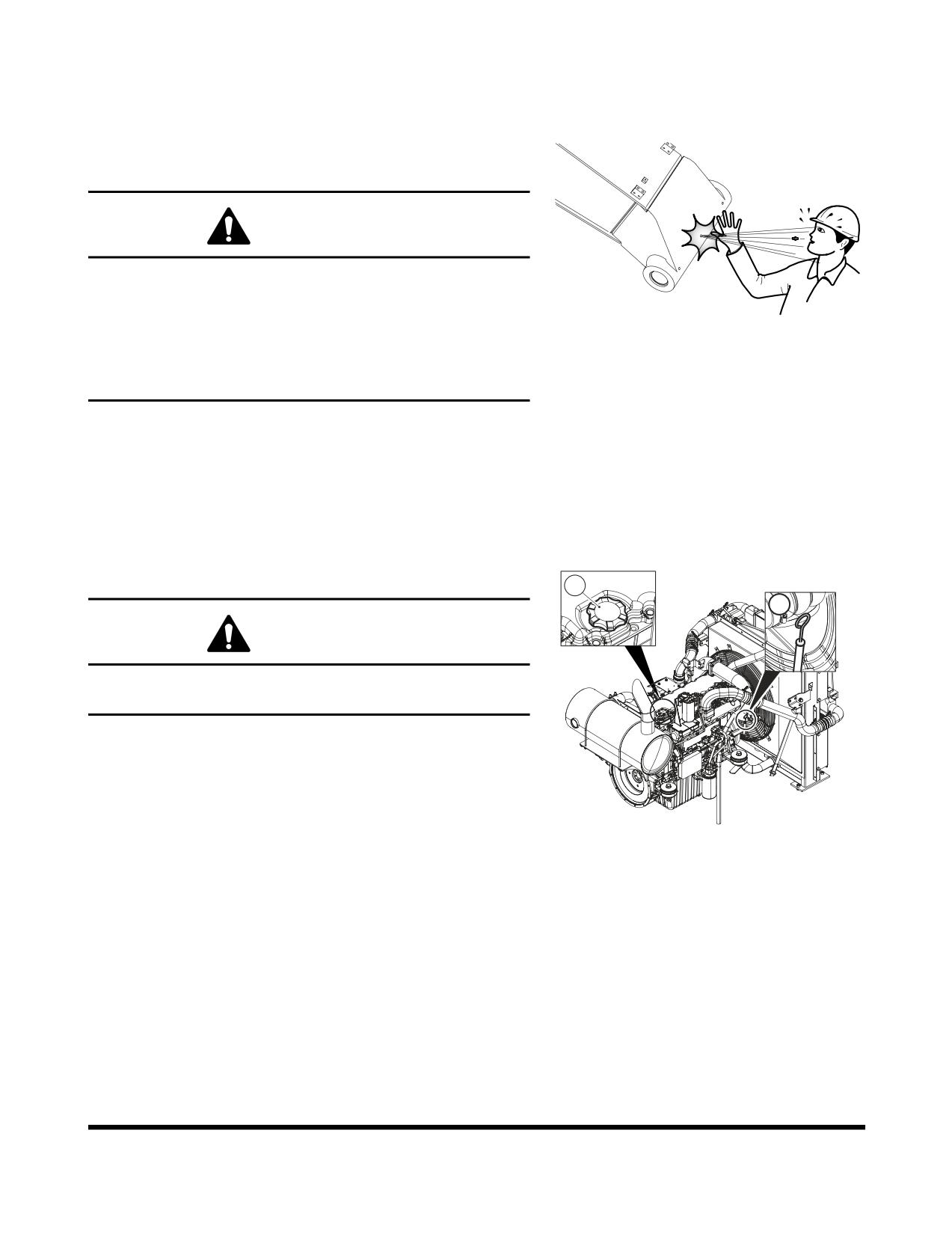
WARNING!
Do not remove the grease fitting until the pressure is
entirely bleed off by loosening grease fitting slowly to
avoid fatal wound.
FG000500
Let anybody never be in the blowing direction.
Figure 12
Be careful to any kinds of works for nipples and
hydraulic line plugs.
Grease every 10 hours for first 100 hours and every 50 or
250 hours thereafter (See page 4-25).
NOTE:
If the unit has been running or working in water the
front attachment should be greased on a 10 hour /
daily basis.
Check Engine Oil Level
2
1
WARNING!
Allow the engine to cool before checking the oil level to
avoid burns by touching hot engine parts.
NOTE:
When checking level using a dipstick always remove
and wipe it clean before making final level check.
1.
Shut down engine and wait for fifteen minutes. This will
allow all oil to drain back to oil pan.
FG007006
2.
Remove dipstick
(1, Figure
13) and wipe the oil off
Figure 13
with a clean cloth.
3.
Insert dipstick fully in the oil gauge tube, then take it
out again.
Inspection, Maintenance and Adjustment
OP000484
4-14
4.
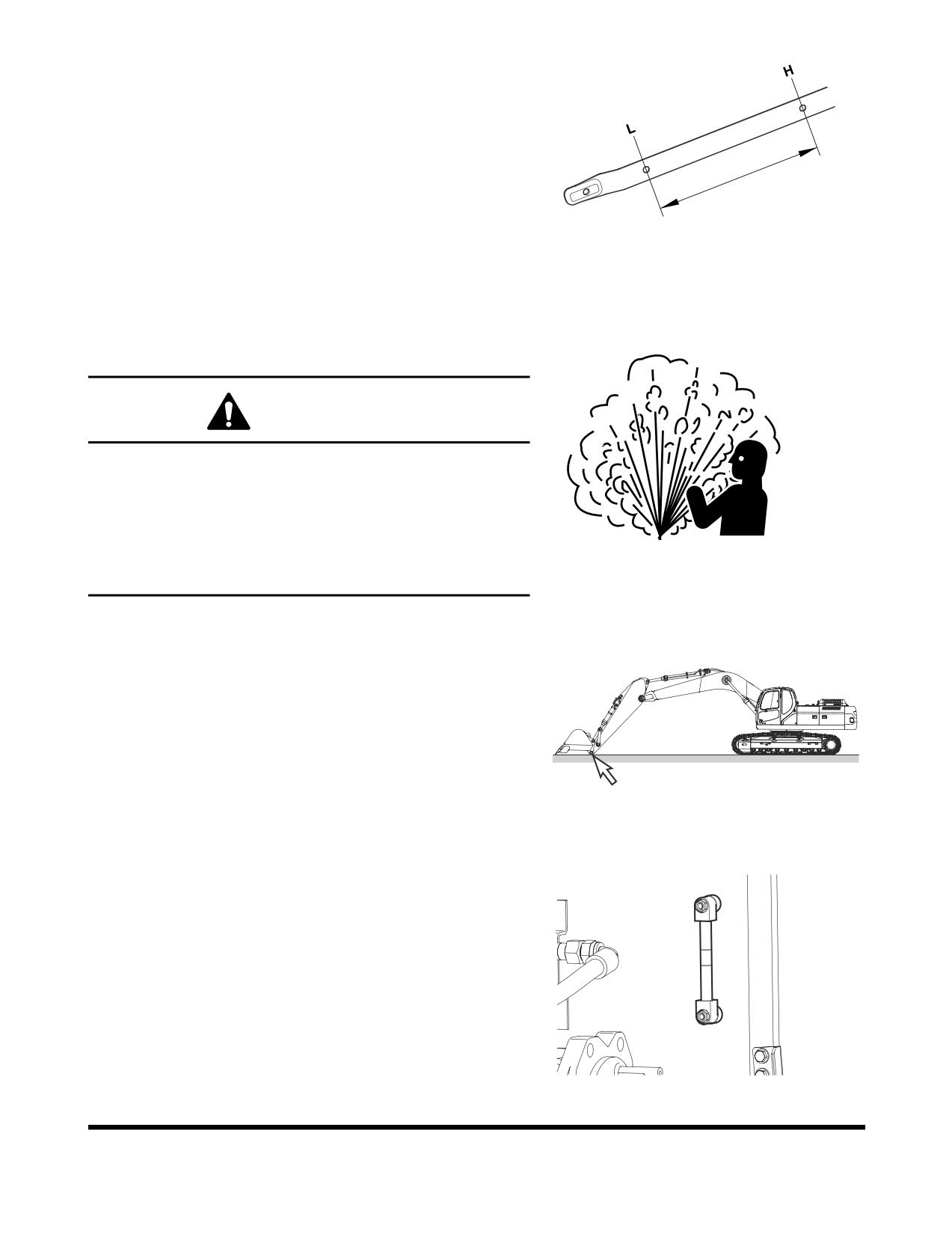
Engine oil level must be between "HIGH" and "LOW"
marks on dipstick.
NOTE:
If oil is above "HIGH" mark on dipstick, some
must be drained to return oil to proper level.
5.
Add oil through engine oil fill cap (2, Figure 13), if the
oil level is below the "LOW" mark.
FG000616
Figure 14
Check Level of Hydraulic Oil Tank
WARNING!
The hydraulic oil will be hot after normal machine
operation. Allow the system to cool before attempting to
service any of the hydraulic components.
The hydraulic tank is pressurized. Turn the breather cap
slowly to allow the pressurized air to vent. After the
ARO1760L
pressure has been released, it is safe to remove either
Figure 15
the fill cap or service covers.
1.
Position the machine on firm, level ground. Lower
boom and position bucket on ground as shown in
Figure 16.
2.
Set engine speed to "LOW IDLE."
FG006941
Figure 16
3.
Set safety lever to "LOCK" position.
4.
Check level gauge by opening right access door. Oil
level must be between marks on sight gauge.
H
L
FG000118
Figure 17
OP000484
Inspection, Maintenance and Adjustment
4-15
5.
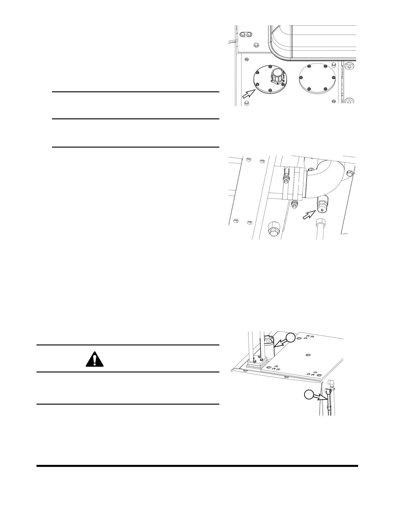
If the level is below "L" mark add oil.
A.
Shut down engine.
B.
The hydraulic tank is pressurized. Turn the
breather cap slowly to allow the pressurized air to
vent.
C.
Remove the upper cover of the hydraulic tank and
add oil.
IMPORTANT
FG006942
Figure 18
Do not fill above "H" mark on sight gauge.
Overfilling can result in damage to equipment and
oil leaking from hydraulic tank due to expansion.
6.
If oil level is above the "H" mark drain oil.
A.
Shut down engine and wait for the hydraulic oil to
cool down.
B.
Drain the excess oil from drain valve (Figure 19)
at the bottom of the tank into a suitable container,
using a hose connected to the valve.
NOTE:
Dispose of drained fluids according to local
regulations.
FG006943
Figure 19
Check for Leaks in Hydraulic System
1.
Perform a daily walk-around inspection to make sure
that the hoses, piping, fittings, cylinders and hydraulic
motors are not showing any signs of leakage. If any is
noted, determine the source of the leak and repair.
Check Fuel Level
1
WARNING!
Use extreme safety precautions while refueling to
prevent explosions or fire.
2
Immediately clean up any split fuel.
FG000130
1.
At end of each work day, fill fuel tank. Add fuel
Figure 20
through fuel fill tube (1, Figure 20). When working at a
temperature of 0°C (32°F) or higher, use ASTM No.
2-D or its equivalent. At temperatures below 0°C (32°F)
use ASTM No. 1-D or its equivalent.
Inspection, Maintenance and Adjustment
OP000484
4-16
2.
Make sure that the fuel fill hose is grounded to the
excavator before fueling begins.
3.
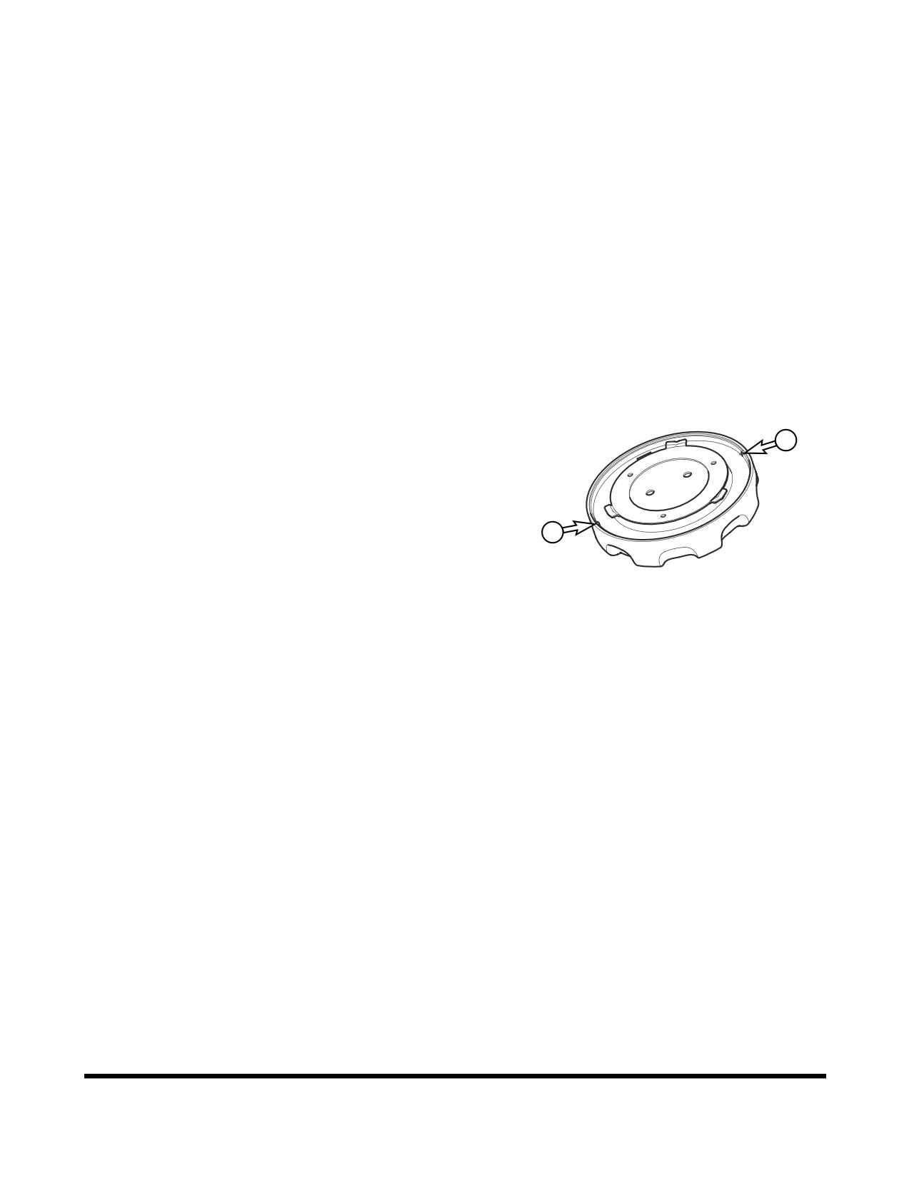
Check the amount of fuel in the tank by observing the
fuel tank sight gauge (2, Figure 20).
NOTE:
See “Fluid Capacities” on page 4-8. for
capacity.
4.
The excavator may be equipped with the optional
battery operated fuel fill pump. The pump assembly is
in the hydraulic pump compartment. Put the suction
hose of the pump into the fuel resupply tank. Turn the
switch in the pump compartment "ON," and the fuel will
be pumped into the excavator fuel tank.
NOTE:
See “Fuel Transfer Pump (Option)” on
page 4-77, for further information.
5.
Do not overfill the tank.
6.
Securely tighten cap after fueling.
NOTE:
If breather holes (3, Figure 21) in cap are
clogged, a vacuum may form in the tank
preventing proper fuel flow to engine. Keep
3
holes in fuel cap clean.
3
FG000317
Figure 21
Check for Leaks in Fuel System
1.
Perform an inspection of the engine compartment to
verify that the fuel system is not leaking. If any is
noted, determine the source of the leak and repair.
OP000484
Inspection, Maintenance and Adjustment
4-17
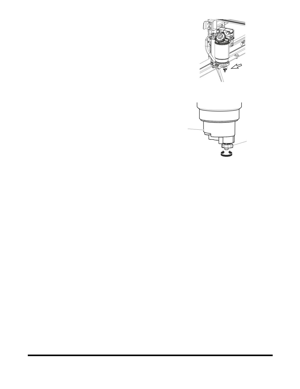
Check Fuel Prefilter and Drain Water As
Required
1.
A fuel prefilter is inside the left rear side access door.
2.
Open the access door on left rear side of the machine.
FG006944
Figure 22
3.
It is necessary to drain the collected water if the bowl
is full of water or sediment.
4.
Position a small container under fuel prefilter. Drain
water or sediment by opening drain valve (2, Figure
23) on bottom of bowl (1).
1
NOTE:
Dispose of drained fluids according to local
regulations.
2
5.
Close drain valve.
open
close
FG000438
Figure 23
Inspection, Maintenance and Adjustment
OP000484
4-18
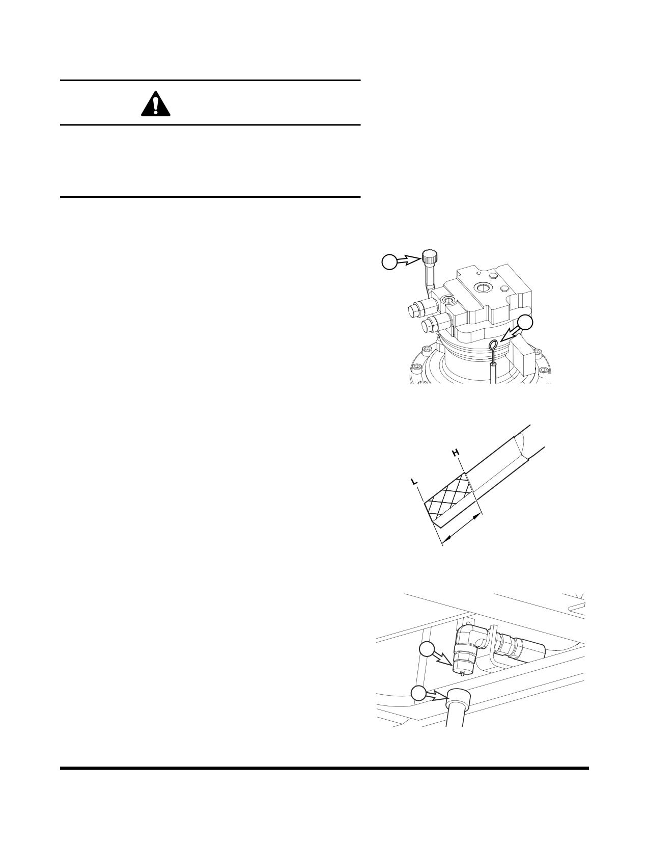
Check Oil Level of Swing Reduction
Device
WARNING!
The gear oil is very hot after the machine has been
operating. Shut all systems down and allow them to
cool. Before fully removing any motor case inspection
port plug, etc., loosen the plug slightly to allow
pressurized air to escape.
NOTE:When checking level using a dipstick always remove
and wipe it clean before making final level check.
1.
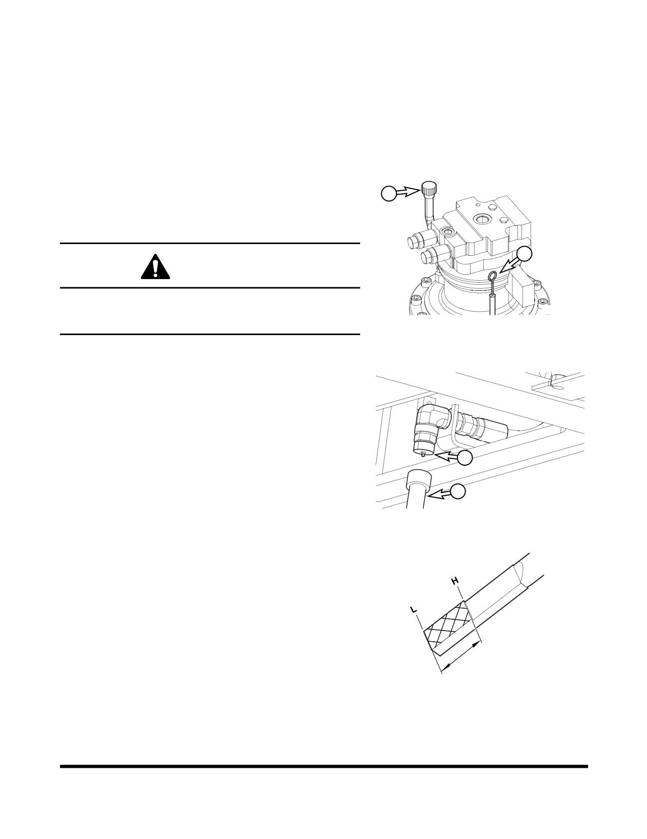
Remove dipstick (1, Figure 24) and wipe the oil from
the dipstick with a cloth.
2
2.
Insert dipstick (1, Figure 24) fully into dipstick tube.
1
FG006969
Figure 24
3.
When dipstick is pulled out, oil level must be between
"HIGH" and "LOW" marks on dipstick.
NOTE:
If oil is above "HIGH" mark on dipstick, some
must be drained to proper level.
4.
If the oil does not reach the "L" mark on the dipstick,
add oil through fill port (2, Figure 24).
FG000419
Figure 25
5.
If the oil level exceeds the "H" mark on the dipstick,
open cap
(3, Figure 26) of drain valve and connect
hose (4) to the valve. Drain the excessive oil into a
suitable container.
NOTE:
Dispose of drained fluids according to local
3
regulations.
4
FG006945
Figure 26
OP000484
Inspection, Maintenance and Adjustment
4-19
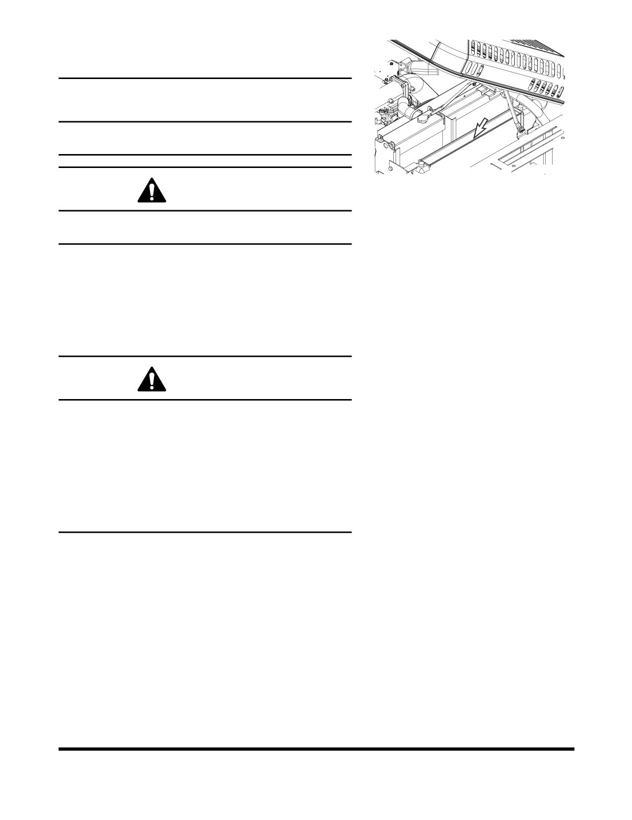
Clean Dust Net in Front of Oil Cooler
and Intercooler
IMPORTANT
If running excavator in dusty area, check
dust net
everyday and clean it if dirty.
FG006946
Figure 27
WARNING!
If using compressed air or water to clean the dust net,
make sure that proper eye protection is worn.
1.
Loosen the wing bolt(s) and remove dust net.
2.
Clean with compressed air or water.
Check Cooling System and Refill As
Required
WARNING!
Allow the engine to cool before releasing the radiator
cap. Make sure to loosen the cap slowly to release any
remaining pressure.
Radiator cleaning is performed while the engine is running.
Take extreme caution when working on or near a running
engine. Make sure to lock out and tag the controls
notifying personnel that service work is being performed.
Do not remove the radiator cap unless it is required.
Observe the coolant level in the coolant recovery tank.
NOTE:
Do not mix ethylene glycol and propylene glycol
antifreeze together. If the two are mixed, the protection
level will be reduced to the level of the ethylene glycol.
Inspection, Maintenance and Adjustment
OP000484
4-20
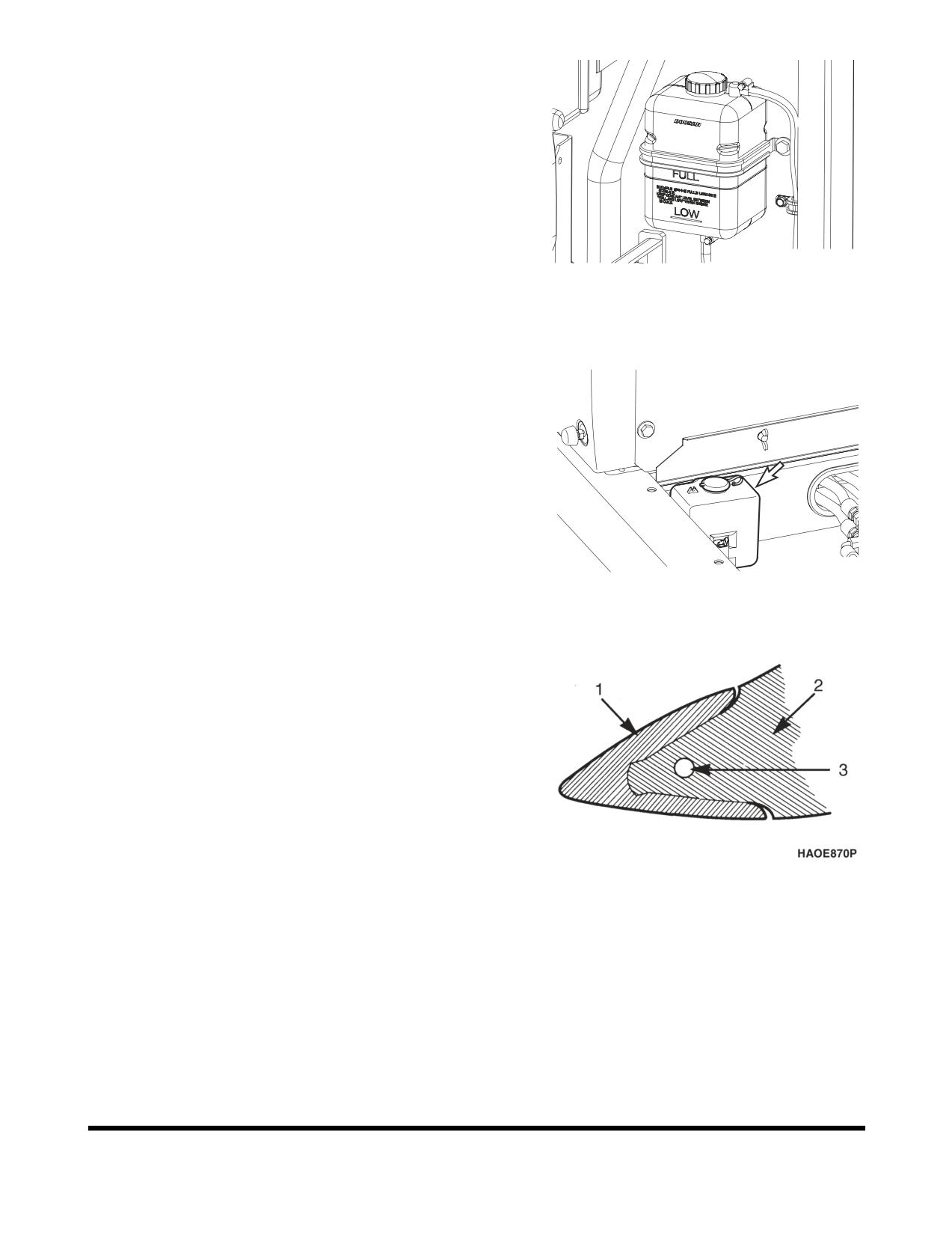
1.
When the engine is cold, remove the radiator cap and
check the coolant level inside the radiator. Do not rely
on the level of coolant in the coolant recovery tank.
Refill
radiator
as required. Refer to coolant
concentration table. (See page 4-76)
2.
Check to make sure that the coolant transfer line from
the coolant recovery tank to the radiator is free and
clear of obstructions, or not pinched.
3.
Observe the level of coolant in the coolant recovery
tank. The normal cold engine fluid level should be
FG006947
between "FULL" and "LOW" marks on tank.
Figure 28
4.
If the coolant is below the "LOW" mark, add coolant to
this tank.
Check Level of Window Washer Liquid
1.
Open left front access door and check fluid level in
windshield washer tank.
2.
Open fill cap and add fluid.
NOTE:
Use a washer liquid that is rated for all seasons.
This will prevent freezing during cold weather
operation.
FG008040
Figure 29
Inspect the Bucket Teeth and Side
Cutters for Signs of Wear
1.
On a daily basis, inspect the bucket teeth to make
sure that tooth wear or breakage has not developed.
2.
Do not allow the replaceable bucket teeth to wear
down to the point that the bucket adapter is exposed.
See Figure 30.
NOTE:
These instructions are only for DOOSAN OEM
buckets. If you are using other manufacturers'
buckets, refer to their specific instructions.
Figure 30
1. POINT, 2. ADAPTER and
3. PIN
OP000484
Inspection, Maintenance and Adjustment
4-21
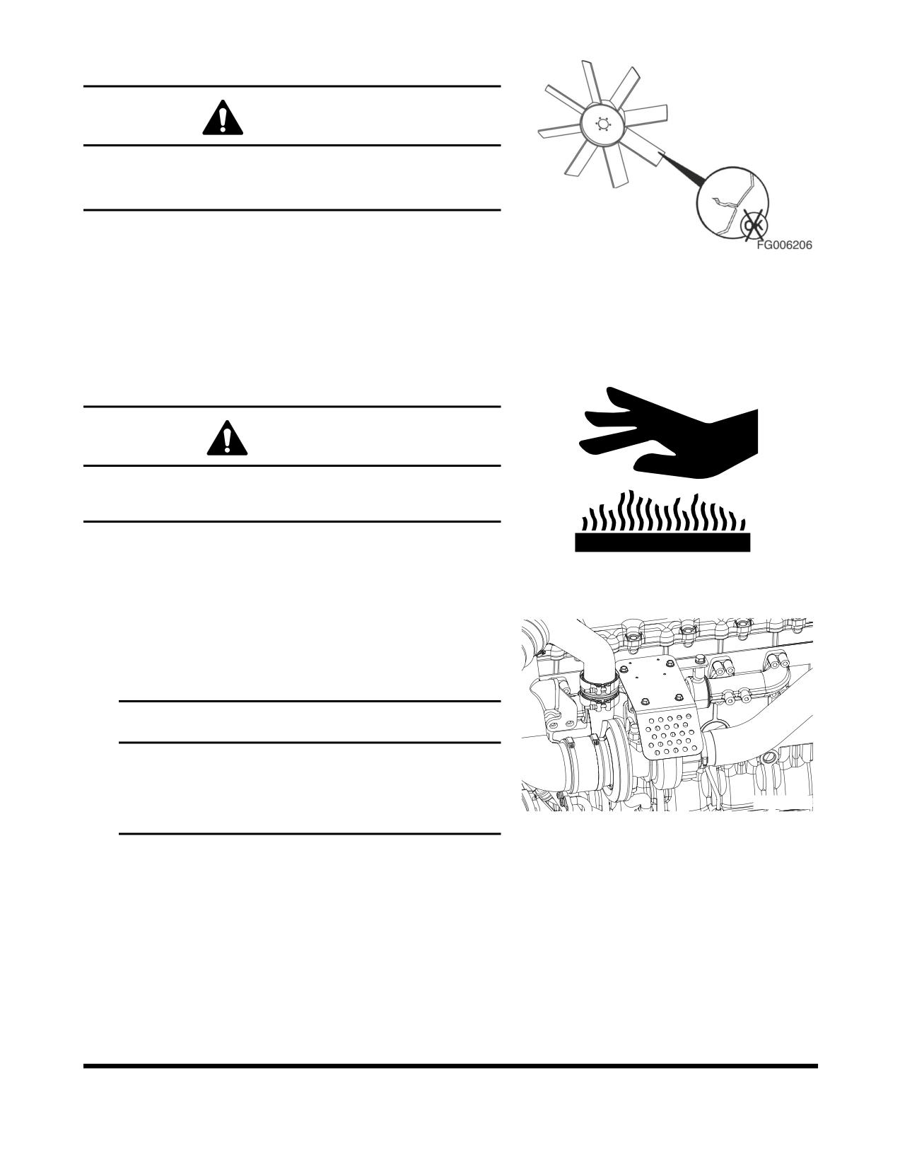
Inspect Cooling Fan Blade
WARNING!
Personal injury can result from a fan blade failure.
Never pull or pry on the fan. This can damage the fan
blade(s) and cause fan failure.
1.
An inspection of the cooling fan is required daily.
Check for cracks, loose bolts, bent or loose blades,
Figure 31
and for contact between the blade tips and the fan
shroud. Check the fan to make sure it is securely
mounted. Tighten the bolts if necessary. Replace any
fan that is damage.
Check Air Intake System
CAUTION!
Hot engine components can cause burns.
Avoid contact with hot engine components
1.
Park the machine on a level surface, lower the
attachment to the ground, set safety lever to "LOCK"
HAOA050L
position, and shut down engine.
Figure 32
2.
Check the engine intake hose, and hose bands for
damage and tightness.
3.
If damaged, wrinkled, or loose, replace or retighten or
contact your nearest DOOSAN dealer.
IMPORTANT
Severe engine damage will result from running with
unfiltered air.
Do not operate engine if any leaks or defects are
FG000421
found on air intake system.
Figure 33
Inspect Seat Belt for Proper Operation
Inspection, Maintenance and Adjustment
OP000484
4-22
Inspect the Structure for Cracks and
Faulty Welds
1.
During the daily walk-around inspection and when
greasing the machine, look for any visible damage to
the machine. Repair or replace any damaged parts
before operating the machine.
Check the Operation of All Switches
1.
Verify the working condition of all switches before
starting the engine.
Check the Operation of All Exterior
Lights, Horn and Control Console
Indicator and Monitor Lights
1.
Turn engine starter switch to the "I" (ON) position and
observe all of the indicator lights.
2.
Restore operation of any light bulbs that do not turn
"ON" at this time.
3.
Sound the horn. Repair or replace if required.
4.
Turn "ON" and inspect all exterior work lights. Replace
any monitors, burned out bulbs or cracked or broken
housings or lenses.
Start Engine, Check Starting Ability, and
Observe Exhaust Color at Start-up
and at Normal Operating
Temperature. Listen for Any
Abnormal Sounds
OP000484
Inspection, Maintenance and Adjustment
4-23
Check Operation of All Controls
IMPORTANT
Cold weather operation requires that the operator fully
warm up the hydraulic oil before beginning machine
operation. Follow all warm up instructions listed in the
Operating Instruction section of this manual. Make sure
to cycle oil through all of the components, including all
cylinders, both travel motors and the swing motor. Cold
hydraulic oil in the lines and components needs to be
warmed before beginning full operation. If this is not
done, damage to the cylinders or hydraulic motors can
occur.
1.
With the engine at rated speed, operate all of the
controls.
2.
Follow cold weather hydraulic system warm-up
procedures.
3.
Note any slow operations or unusual movements.
Determine the cause and repair the fault before
operating.
Inspection, Maintenance and Adjustment
OP000484
4-24
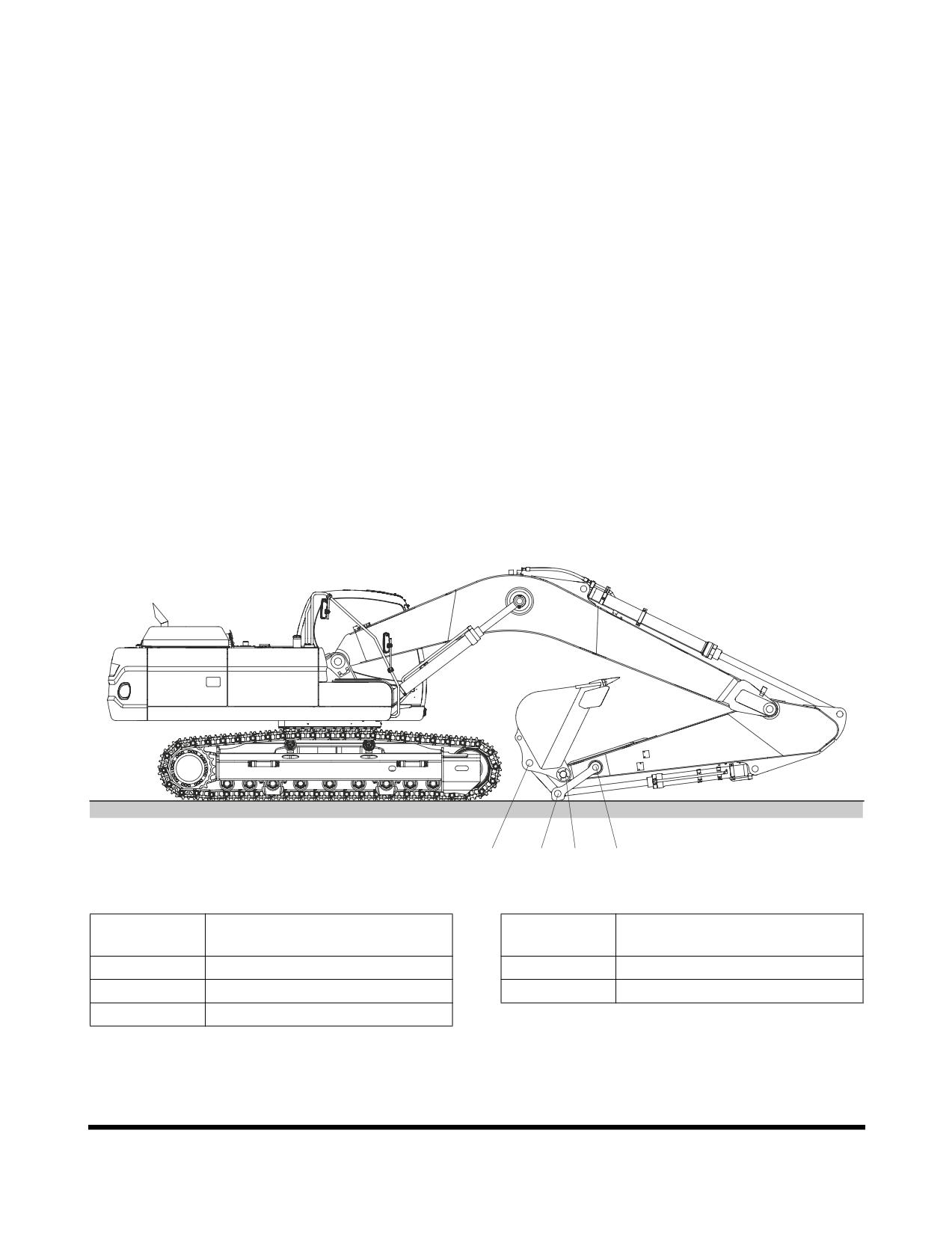
50 HOUR / WEEKLY SERVICE
Perform All Daily Service Checks
Grease Arm and Front Attachment Pins
Grease every
10 hours for first 100 hours and every
50
hours thereafter.
NOTE:
If the unit has been running or working in water the
front attachment should be greased on a 10 hour /
daily basis.
•
Position machine as shown below and lower the
front attachment to the ground and shut down
engine
•
Press the grease fitting and inject grease with the
grease gun on the marked point
•
After injection, clean off the old grease that has
been purged.
D
B,E
C
A
FG006949
Figure 34
Reference
Reference
Description
Description
Number
Number
A
Arm Link Joint Pin (1 Points)
D
Bucket Link Joint Pin (1 Point)
B
Link Joint Pin (2 Points)
E
Bucket Cylinder Rod Pin (1 Point)
C
Arm Bucket Joint Pin (1 Points)
OP000484
Inspection, Maintenance and Adjustment
4-25
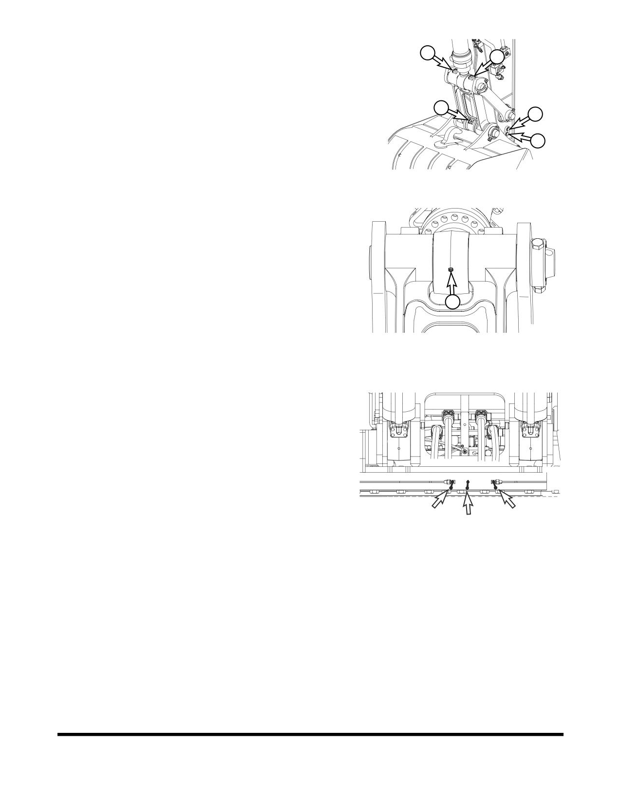
A.
Arm link joint pin (1 point)
B
B.
Link joint pin (2 points)
B
C.
Arm bucket joint pin (1 point)
D.
Bucket link joint pin (1 point)
D
A
C
FG001438
Figure 35
E.
Bucket cylinder rod pin (1 point)
E
FG001439
Figure 36
Grease Swing Bearing
1.
Position the machine on firm, level ground. Lower the
front attachment to the ground and shut down engine.
2.
There are three grease fittings for the swing bearing.
Do not over lubricate. Purge old grease with new.
Remove all purged grease.
FG006950
Figure 37
Inspection, Maintenance and Adjustment
OP000484
4-26
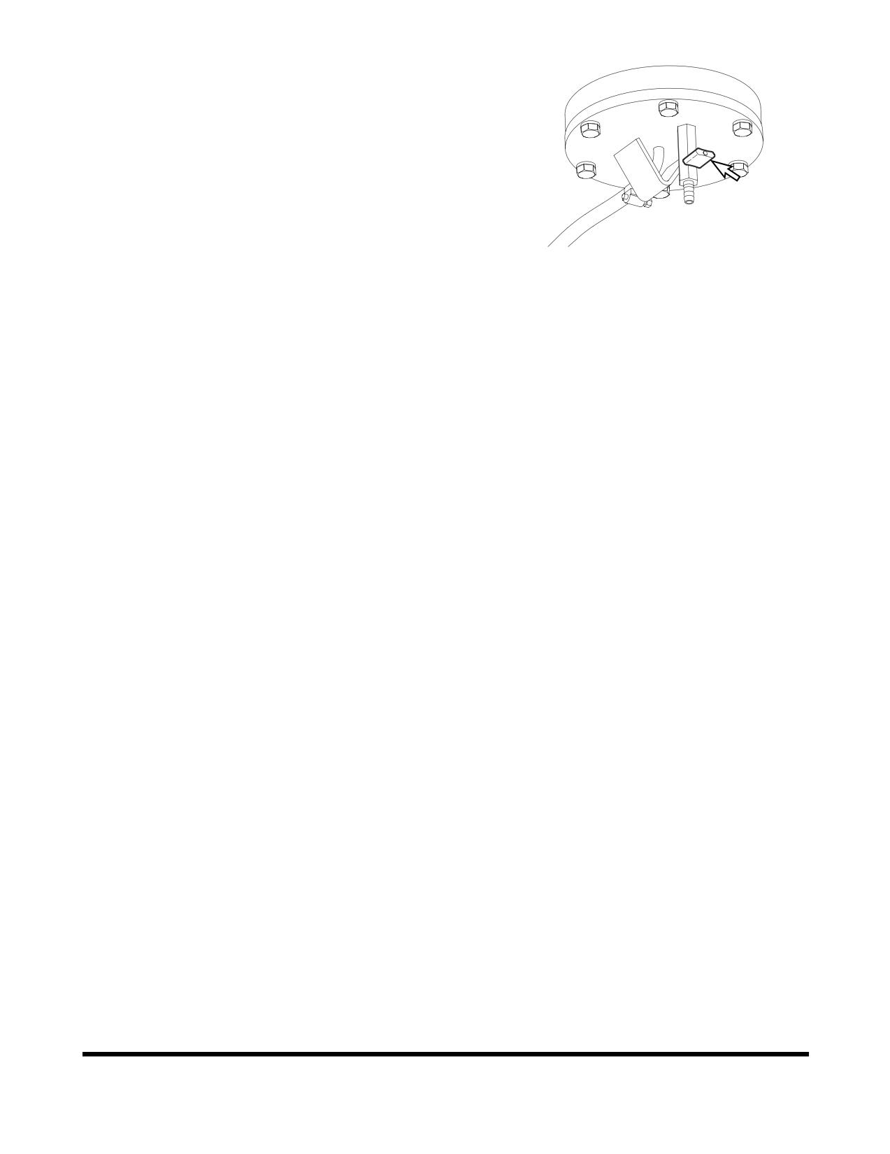
Drain Water and Sediment from Fuel Tank
1.
Perform this procedure before operating the machine.
2.
Drain water and sediment from bottom of fuel tank into
a suitable container.
NOTE:
Dispose of drained fluid according to local
regulations.
NOTE:
Always completely fill fuel tank at end of each
workday to prevent condensation from forming
on the inside walls of the tank.
FG000296
Figure 38
Check Engine Fan Belt for Cracks, Wear
and Correct Tension (After First 50
Hours)
1.
Inspect after first 50 hours of operation and every 250
hours thereafter. For details, See “Check Engine Fan
Belt Tension” on page 4-31.
Change Engine Oil and Filter (After First
50 Hours)
1.
Change engine oil and filter after first
50 hours of
operation or rebuild, then every
500 thereafter. For
details, See “Change Engine Oil and Filter” on
page 4-36.
Inspect the Track Assemblies for Proper
Tension and Loose, Worn or Damaged
Parts (Links, Shoes, Rollers, Idlers)
1.
Do a daily walk-around inspection of all components
including the track assemblies. Look for missing,
damaged or excessively worn parts. See “Track
Tension” on page 4-81.
2.
Jack up each track and perform the two speed travel
motor test.
OP000484
Inspection, Maintenance and Adjustment
4-27
250 HOUR / MONTHLY
SERVICE
Perform All Daily and 50 Hour Service
Checks
Change Swing Reduction Device Oil
(Drain and Refill After First 250
Hours)
NOTE:
Change swing reduction device oil after first
250
hours on a new machine and every 2,000 hours
thereafter (See page 4-51).
Inspection, Maintenance and Adjustment
OP000484
4-28
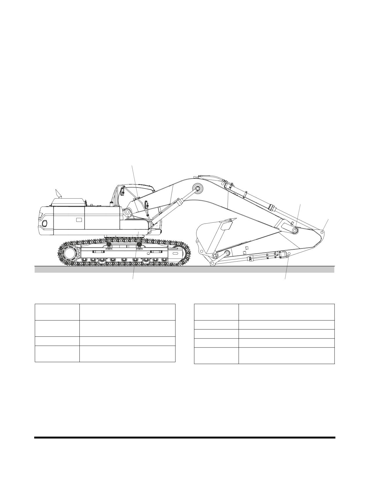
Grease Arm and Front Attachment Pins
Grease every 10 hours for first 100 hours and every 250
hours thereafter.
NOTE:
If the unit has been running or working in water the
front attachment should be greased on a 10 hour /
daily basis.
•
Position machine as shown below and lower the
front attachment to the ground and shut down
engine
•
Press the grease fitting and inject grease with the
grease gun on the marked point
•
After injection, clean off the old grease that has
been purged.
B,C,D
E
F
A
G
FG006951
Figure 39
Reference
Reference
Description
Description
Number
Number
A
Boom Cylinder Head Pin
D
Arm Cylinder Head Pin (1 Point)
(2 Points)
E
Boom Arm Joint Pin (2 Points)
B
Boom Foot Pin (2 Points)
F
Arm Cylinder Rod Pin (1 Point)
C
Boom Cylinder Rod Pin
G
Bucket Cylinder Head Pin
(2 Points)
(1 Point)
OP000484
Inspection, Maintenance and Adjustment
4-29
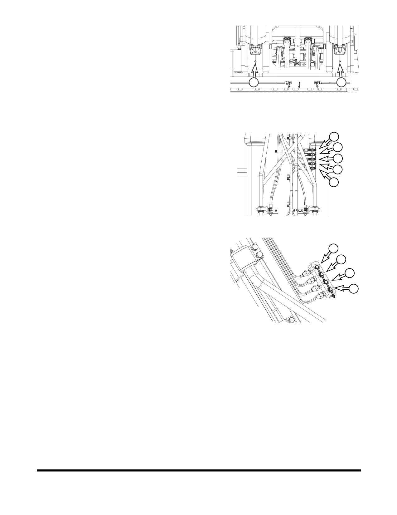
A.
Boom cylinder head pin (2 points)
A
A
FG006952
Figure 40
B.
Boom foot pin (2 points)
C
C.
Boom cylinder rod pin (2 points)
D
D.
Arm cylinder head pin (1 point)
C
B
B
FG006953
Figure 41
E.
Boom arm joint pin (2 points)
F.
Arm cylinder rod pin (1 point)
E
E
G. Bucket cylinder head pin (1 point)
F
G
FG006954
Figure 42
Inspection, Maintenance and Adjustment
OP000484
4-30
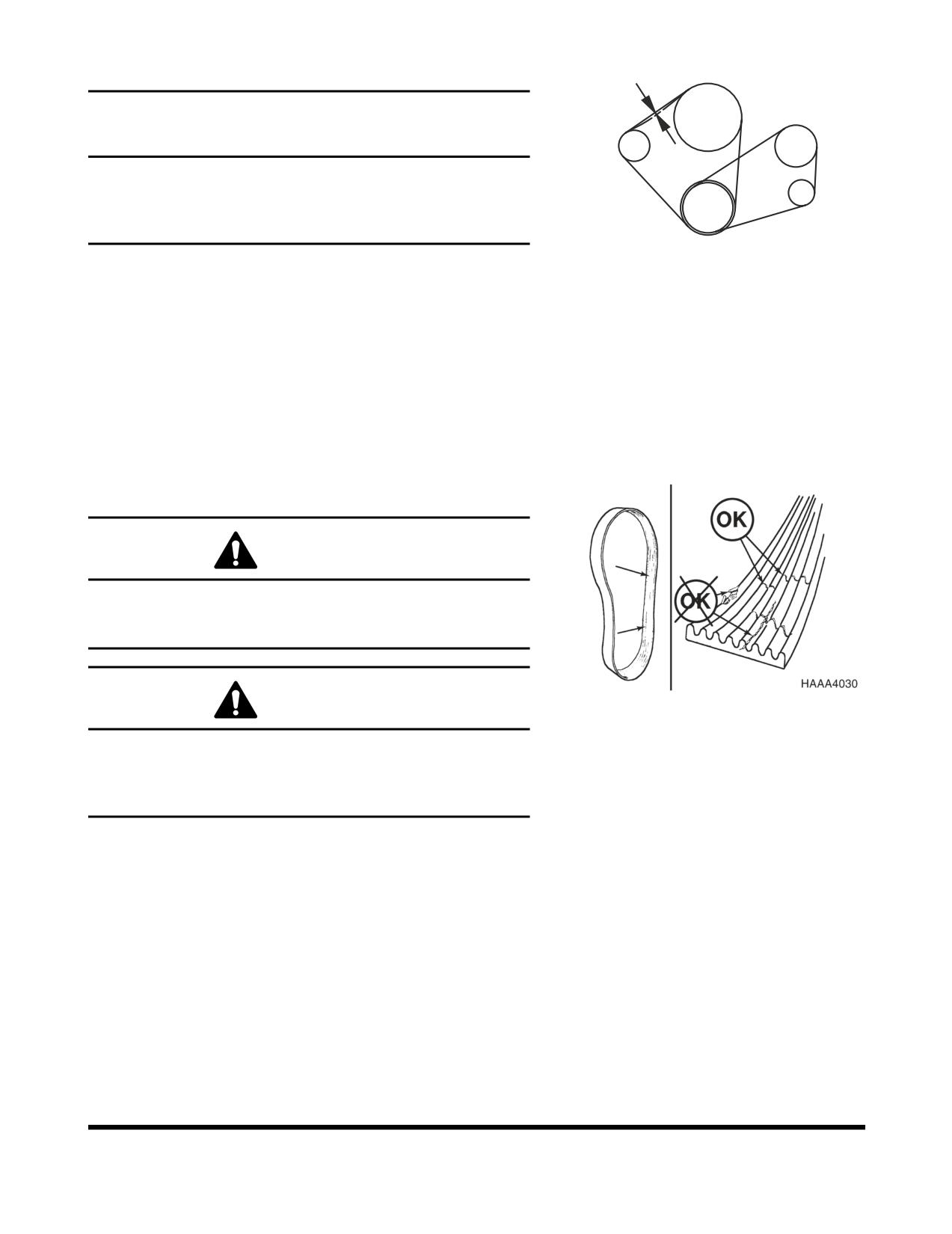
Check Engine Fan Belt Tension
FAN
10mm/10kg
COMPRESSOR
IMPORTANT
A loose fan belt can cause engine overheating, poor
ALTERNATOR
charging, and/or premature belt wear. A belt that is too
tight can cause damage to the water pump, alternator
bearing or belt.
CRANKSHAFT
FG000353
1.
Inspect every 250 hours. (Inspect after first 50 hours of
Figure 43
operation.)
2.
With the engine shut off, check the tension of the fan
belt by pressing downwards on the belt, midway
between the fan pulley and alternator pulley. The belt
should flex approximately 10 mm (0.4 in). See Figure
43. To adjust the belt, loosen the alternator adjustment
plate bolts, adjust the belt tension and retighten the
bolts.
Check Engine Fan Belt Wear
WARNING!
Keep clear of engine fan and fan drive belts when the
engine is running. Rotating fan and belt contact can
cause injury.
Figure 44
WARNING!
When checking, adjusting or replacing drive belts, care
must be taken to prevent accidental cranking of the
engine. Be sure the starter switch is in the "OFF"
position and the controls are tagged.
1.
Replace badly worn, greasy or severely cracked belts
immediately. These conditions prevent proper belt
function. Visually inspect the belt. Check the belt for
intersecting cracks. Transverse (across the belt width)
cracks are acceptable. Longitudinal (direction of belt
length) cracks that intersect with transverse cracks are
not acceptable. Replace the belt if it is frayed or has
pieces of material missing.
2.
Before installing new belts, make sure all pulley
grooves are clean and not worn. Replace pulley, if
damaged, or if the grooves are worn.
3.
All pulley support bearings, shafts, and brackets must
be in working order.
OP000484
Inspection, Maintenance and Adjustment
4-31
4.
When replacing belts and pulleys, pulley alignment
must be checked with belts tensioned and brackets
securely clamped. A misalignment that can be detected
by the naked eye is detrimental to belt performance.
5.
Do not force the belts into the pulley grooves by prying
with a screwdriver or pry bar. This will damage the belt
side cords which will cause the belts to turn and result
in complete destruction of the belts in operation.
6.
Belts on new machines and replacement belts lose
their tension as they seat into the pulley grooves.
Check the tension of new belts at 50 hour intervals
until tension is stabilized and thereafter, every
250
hours. If the tension falls below the required minimum,
the belt slips damaging the belts and pulley grooves.
NOTE:
When operating in abrasive conditions, check
tension every 100 hours.
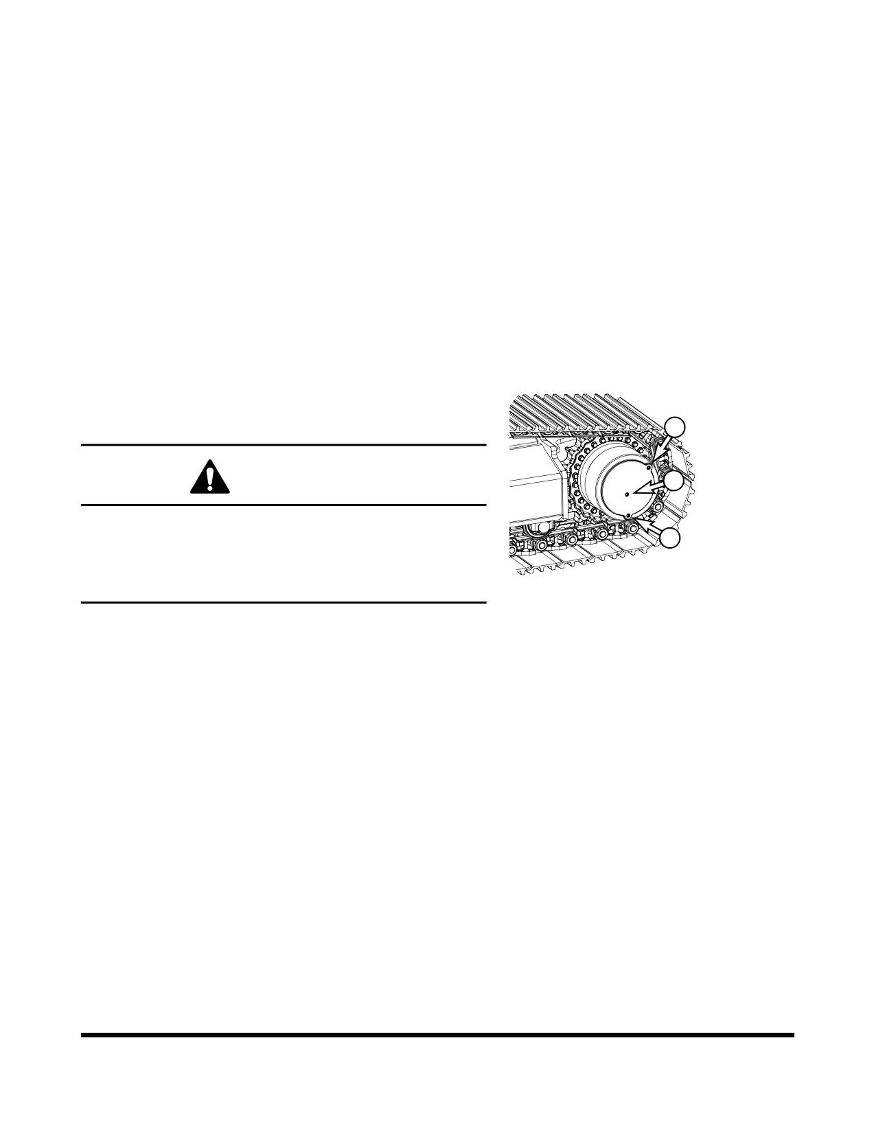
Check Oil Level in Travel Reduction
Device (One on Each Side of Unit)
3
WARNING!
1
The gear oil is very hot after the machine has been
operating. Shut all systems down and allow them to
2
cool. Before fully removing any motor case inspection
port plug, etc., loosen the plug slightly to allow
FG006955
pressurized air to escape.
Figure 45
1.
Make sure that the machine is on firm, level ground.
2.
Rotate the track until ports (1 thru 3, Figure 45) are in
their proper positions as shown.
3.
Loosen fill plug
(3, Figure
45) slightly to allow
pressurized air to escape.
4.
Remove oil level plug (1, Figure 45).
5.
Check oil level. The oil should be near the bottom of
the level plug opening.
6.
Add oil through the fill plug (3, Figure 45) opening, if
necessary.
7.
Clean and install oil level and fill plugs
(1 and
3,
Figure 45).
8.
Repeat this procedure on the other travel reduction
device.
Inspection, Maintenance and Adjustment
OP000484
4-32
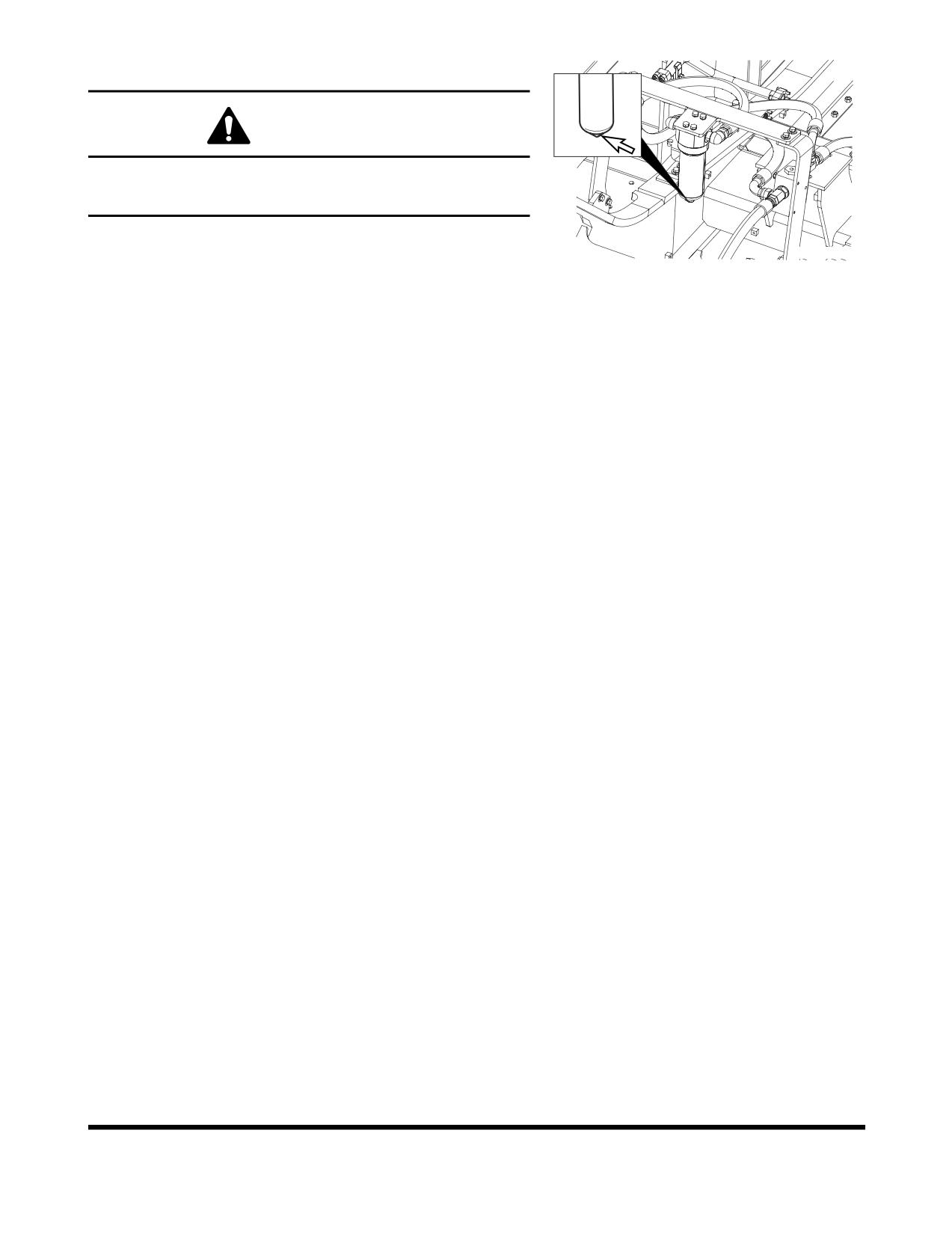
Change Breaker Filter Element (Optional)
WARNING!
The hydraulic oil will be hot after normal machine operation.
Allow the system to cool down before changing pilot filter.
1.
Position the machine on firm, level ground. Lower the
FG006956
front attachment to the ground and shut down engine.
Figure 46
2.
Loosen the hydraulic oil tank breather cap to release
pressure.
3.
Locate breaker filter assembly (Figure 46).
4.
Position a container under the filter assembly. Remove
the drain plug and completely drain the assembly.
5.
Using a 30 mm spanner, unscrew filter housing from
filter bottom.
6.
Remove O-ring from filter head.
7.
Replace filter.
8.
Apply a small amount of oil around the entire O-ring
and install the filter housing on the filter head.
NOTE:
Tightening torque : 27 kg•m (265 Nm, 195 ft lb)
9.
Install drain plug in bottom of filter housing.
10. After changing breaker filter, vent air from pump and
check level of hydraulic oil tank.
Change Oil in Travel Reduction Device
(One on Each Side of Unit) (After
First 250 Hours)
NOTE:
Drain and refill oil after first 250 hours of operation or
rebuild, and every 1,000 hours thereafter (See page
4-47).
Change Hydraulic Oil Return Filter (After
First 250 Hours)
NOTE:
Change hydraulic oil return filter after first 250 hours
of operation or rebuild, then every
1,000 hours
thereafter (See page 4-45).
Change Pilot Filter (After First 250 Hours)
NOTE:
Change pilot filter after first 250 hours and every
1,000 hours thereafter (See page 4-46).
OP000484
Inspection, Maintenance and Adjustment
4-33
Inspect Pins and Bushings of the Front
End Attachments for Signs of Wear
Check Fluid Levels in Batteries and
Battery Charge Levels
Inspect for Any Loose or Missing Nuts
and Bolts
Inspect Fuel System Hose Clamps
Inspection, Maintenance and Adjustment
OP000484
4-34
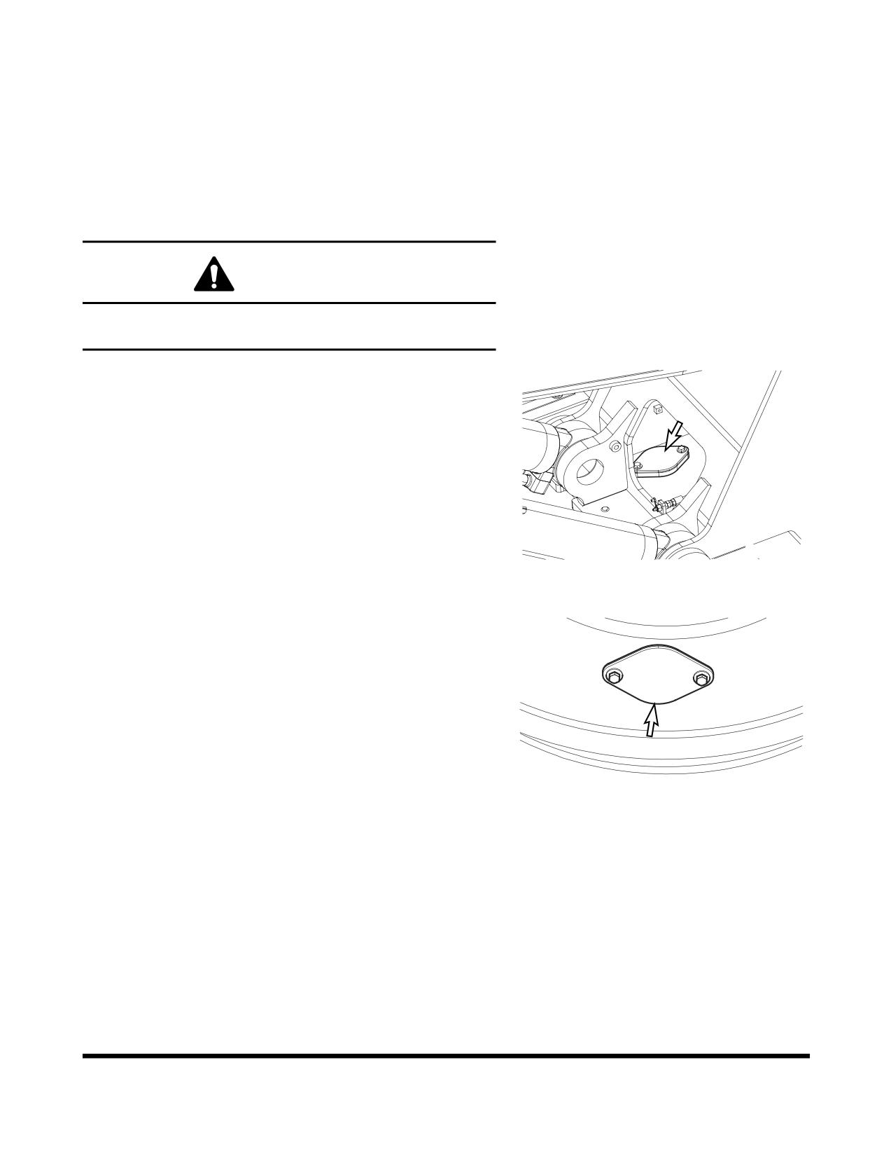
500 HOUR / 3 MONTH SERVICE
Perform All Daily, 50 and 250 Hour
Service Checks
Grease Swing Gear and Pinion
WARNING!
Greasing swing gear and pinion must be serviced by
only one person.
1.
Remove inspection cover and inspect the condition of
the grease. Make sure that water or other contaminants
are not noticeable.
NOTE:
The upper structure must be rotated a little at a
time so that the entire face of the swing gear
can be lubricated. Use extreme caution when
performing this operation.
FG006957
Figure 47
2.
If water or other contaminations are found, remove the
lower access cover so that the gear teeth can be
thoroughly cleaned and lubricated.
3.
Install access covers after lubricating gear teeth.
FG000148
Figure 48
OP000484
Inspection, Maintenance and Adjustment
4-35
Change Engine Oil and Filter
NOTE:
Change engine oil and filter after first 50 hours of
operation or rebuild, then every 500 thereafter.
WARNING!
DO NOT change oil on a hot engine. Allow the engine
to cool down before attempting to change the engine oil
and filter to avoid burns by touching hot engine parts.
1.
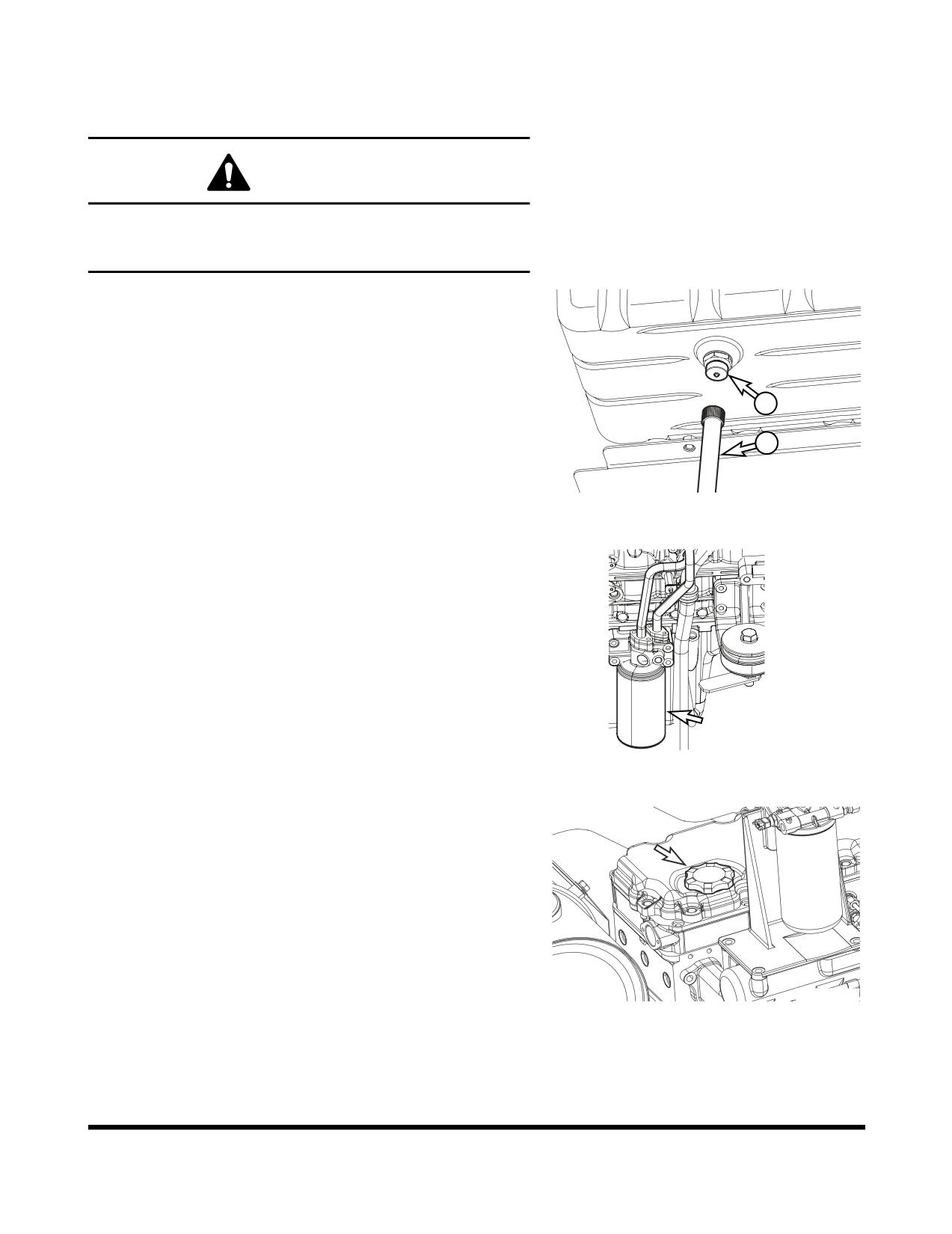
Position a larger container under the engine. Remove
cap
(1, Figure
49) and install hose
(2) to drain the
engine oil. Remove hose (2) and install cap (1).
NOTE:
Dispose of drained fluids according to local
regulations.
1
2
FG000144
Figure 49
2.
Replace engine oil filter by using filter wrench. The
engine oil filter is a spin-on type. See Figure
50.
Remove and discard filter.
3.
Install new filter. Apply a small amount of oil around
filter gasket. Screw filter on head until gasket contacts
head, turn filter 1/2 turn more.
FG006958
Figure 50
4.
Refill the engine with the correct oil through the oil fill
port (Figure 51). Refer to the Lubrication Table of this
manual for the recommended oil for the operating
conditions.
NOTE:
See “Fluid Capacities” on page 4-8. for
capacity.
5.
Start engine. Run engine for five minutes at "LOW
IDLE," and check engine oil pressure light.
6.
Shut down engine. Look for signs of leaks at filter.
Recheck oil level after fifteen minutes.
FG006314
Figure 51
Inspection, Maintenance and Adjustment
OP000484
4-36
Clean Air-Conditioning Outer Filter
The unit is equipped with an air filtration system which filters
out dirt and dust particles from air being circulated into
operator's cabin. This filter should be cleaned out.
NOTE:
In the event that the unit is being operated in a dusty
environment, the cleaning and replacement should
be performed more frequently. If filter is damaged,
replace damaged filter with a new one.
WARNING!
All service and inspection of air-conditioning system
should be performed with the starter switch in the "O"
(OFF) position.
WARNING!
If using compressed air to clean the element, make sure
that proper eye protection is worn.
NOTE:
All right and left call outs are based on the operator
being seated in the operator's seat facing the front.
1.
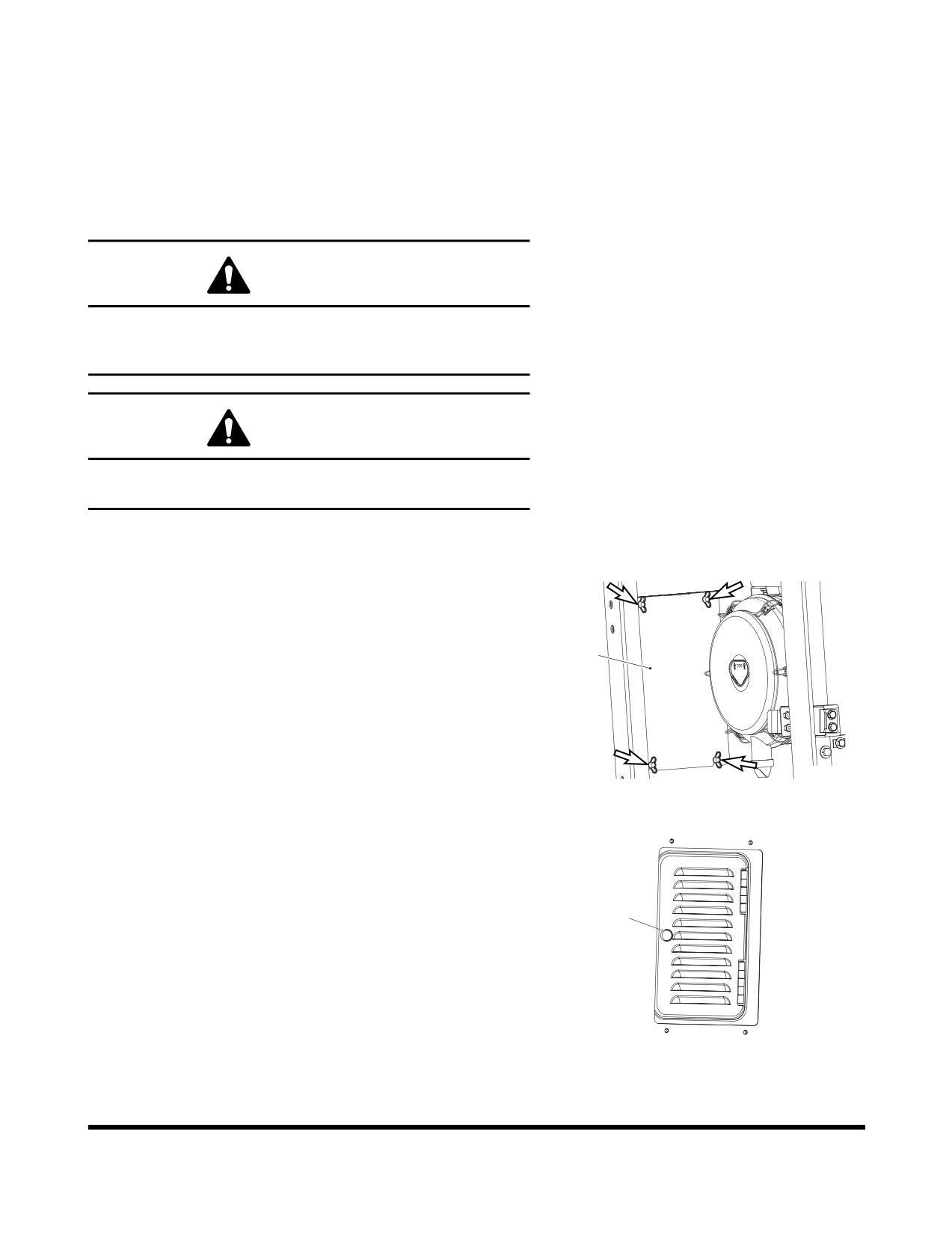
Open the door in the left front of the machine, then
remove the cover (1, Figure 52) by loosening the four
wing bolts.
1
Donaldson.
FG000440
Figure 52
2.
Open the cover by turning the knob (1, Figure 53) in
the rear of the cabin.
1
FG000441
Figure 53
OP000484
Inspection, Maintenance and Adjustment
4-37
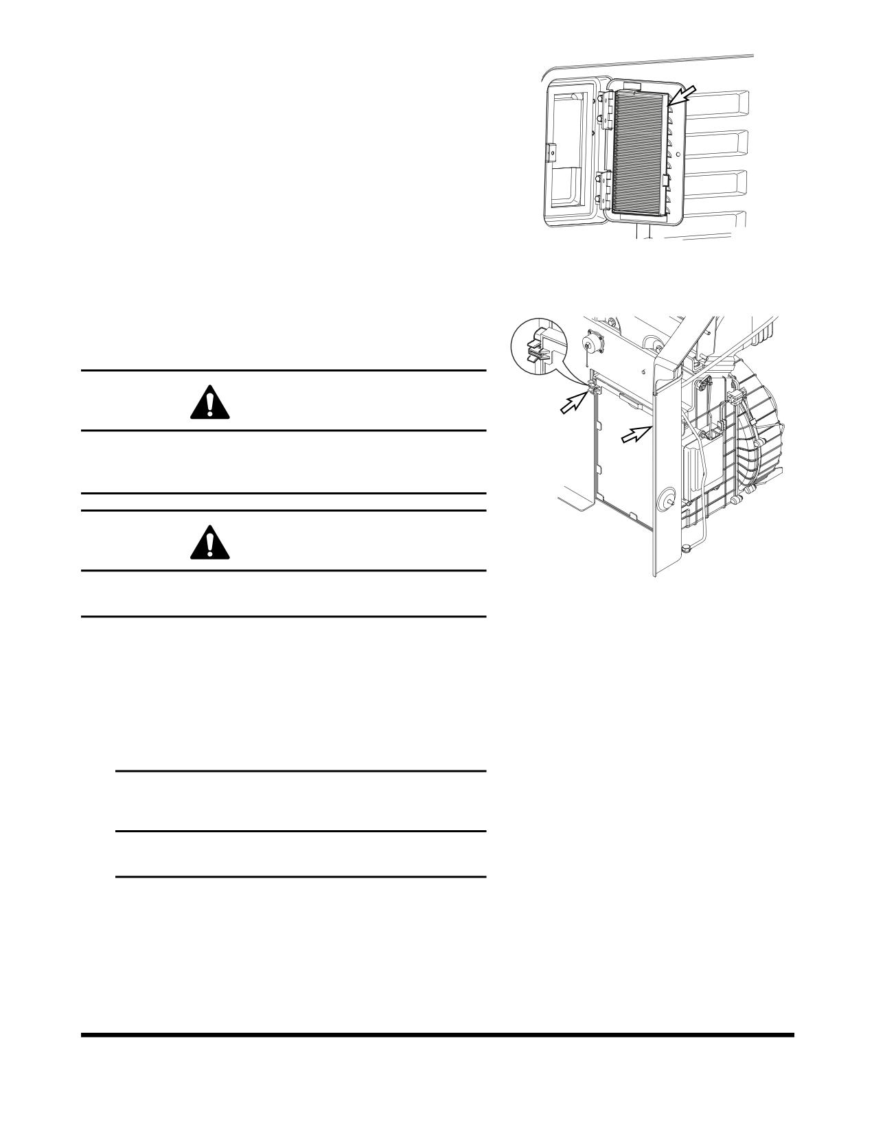
3.
Remove filter (Figure 54) and inspect for any damage.
4.
Use compressed air to clean filter. If filter is still dirty,
then change to new one.
5.
Reassemble in reverse order.
FG000342
Figure 54
Check and Clean Air-Conditioning Inner
Filter
WARNING!
All service and inspection of air-conditioning system
should be performed with the starter switch in the "O"
(OFF) position.
WARNING!
FG000422
If using compressed air to clean the element, make sure
Figure 55
that proper eye protection is worn.
1.
Remove the filter by pulling out ward the knob while
pressing the upper part and lower part of the filter
handle which is inside of the left rear part of the cabin.
2.
Use compressed air in the clean filter. If the filter is
damaged replaced by a new one.
If the filter is very dirty use a mild soap or detergent
and water to clean it.
IMPORTANT
If water was used to clean filter, be certain it is
completely dry before installing.
Inspection, Maintenance and Adjustment
OP000484
4-38
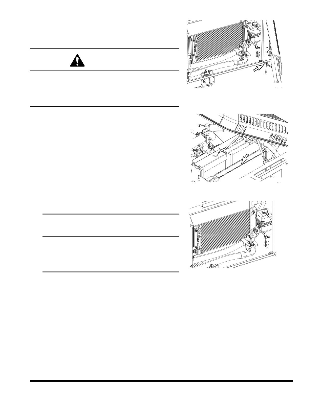
Clean Radiator, Oil Cooler, Intercooler,
Fuel Cooler and Air Conditioner
Condenser Core
WARNING!
If compressed air, steam or water hit your body directly,
there is danger of injury. Always wear protective
FG006960
glasses, mask and safety shoes during the cleaning
Figure 56
precess. Make sure that all extra personnel are clear of
the work area.
1.
Open the rear left door and engine cover.
2.
Loosen the wing bolt(s) and remove dust net from in
front of oil cooler and intercooler.
3.
Clean the outside of the radiator and oil cooler,
intercooler and fuel cooler with compressed air, steam
or water. Wash from the outside of the engine
compartment inwards. Repeat the cleaning process
from the inside of the engine compartment outwards to
remove all dirt and debris.
NOTE:
Clean dust net and install it after cleaning
FG006946
radiator, oil cooler, intercooler and fuel cooler.
Figure 57
4.
Clean air conditioner condenser core with compressed
air, steam or water.
IMPORTANT
To prevent damage to the cores, apply compressed
air from an appropriated distance. Damaged core
may cause water leakage or overheating. In a dusty
site, check the core daily, irrespective of the
maintenance interval.
FG006960
Figure 58
OP000484
Inspection, Maintenance and Adjustment
4-39
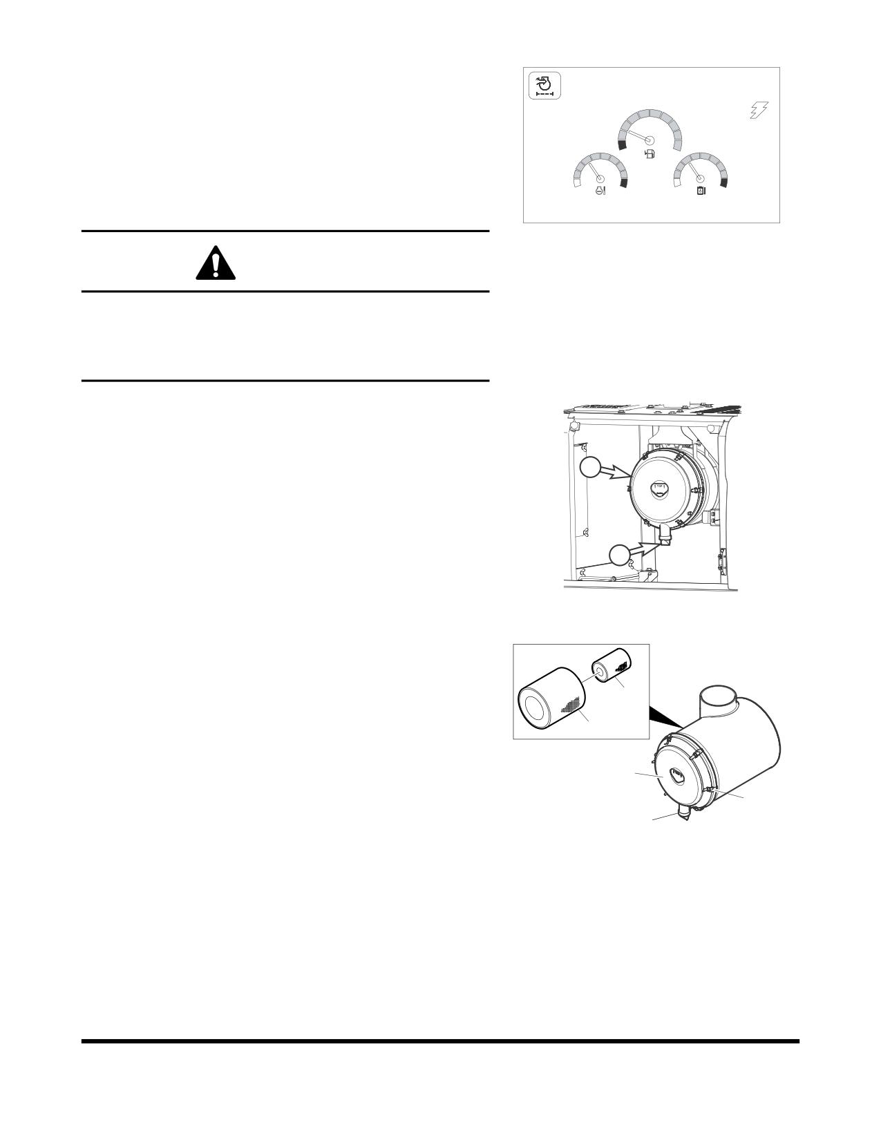
Clean Outer Filter of Air Cleaner
02/05 [MO] 11:30
NOTE:
Clean outer filter every 500 hours / 3 months of
service.
NOTE:
If air cleaner clogged warning light (Figure 59)
on instrument panel comes "ON" the air cleaner
E
F
must be serviced.
C
H
C
H
NOTE:
When working in severely dusty conditions, the
service interval should be shortened.
E/G SPEED 1700 RPM
FG000264
Figure 59
WARNING!
Never clean or attempt to remove the air cleaner filter if the
engine is running.
If using compressed air to clean the filter, make sure that
proper eye protection is worn.
1.
Locate the air cleaner assembly.
NOTE:
When it reaches every 500 hours or If indicator
light (Figure 59) on instrument panel comes
"ON" the air cleaner must be serviced.
2
NOTE:
Change outer filter after cleaning 5 times or
every 2,000 hours / 1 year of service.
2.
Remove and clean rubber evacuator valve (1, Figure 60)
from bottom of air cleaner housing cover (2). Inspect seal
1
lips for wear or damage. Replace valve if necessary.
FG000297
NOTE:
Install evacuator valve with lips parallel to the
Figure 60
cover.
3.
Remove the access cover (2, Figure 61) by loosening the
latches (3).
4.
Remove the outer filter (4, Figure 61) from the housing. Do
5
not remove inner filter (5).
4
2
3
1
FG000702
Figure 61
Inspection, Maintenance and Adjustment
OP000484
4-40
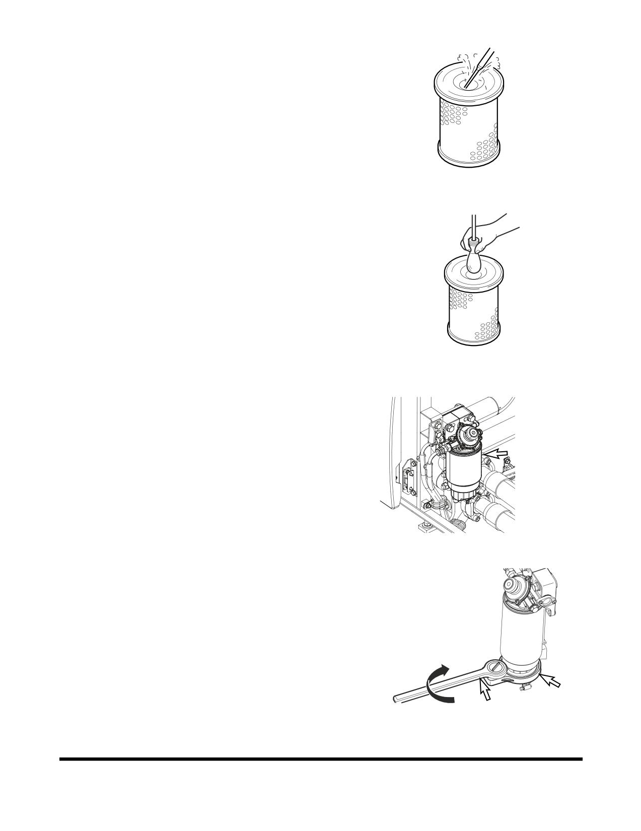
5.
Clean the outer filter
(4, Figure
61) by blowing
compressed air from the inside of the filter towards the
outside. Do not use more than 205 kPa (30 psi) air
pressure.
HAOC570L
Figure 62
6.
Check outer filter by shinning a light through it. If small
holes or thinner parts are found on the element after
cleaning it, replace the filter.
7.
Clean the inside of the air cleaner body and the inside
of the air cleaner cover. Do not use compressed air.
8.
Properly install the air filter and cover.
9.
After filter service be sure to install cover with arrows
pointing "UP."
NOTE:
If after cleaning the outer filter, the air cleaner
FG000412
clogged indicator remains "ON," replace the
Figure 63
outer and inner filters. Do not clean inner filter.
Change of Fuel Prefilter
1.
Open the left rear side door to access fuel prefilter.
2.
Position a small container under prefilter. Drain fuel by
opening drain valve on bottom of filter.
NOTE:
Dispose of drained fluids according to local
regulations.
FG006961
Figure 64
3.
Remove the bowl using supplied tool.
4.
Remove the cartridge.
FG006962
Figure 65
OP000484
Inspection, Maintenance and Adjustment
4-41
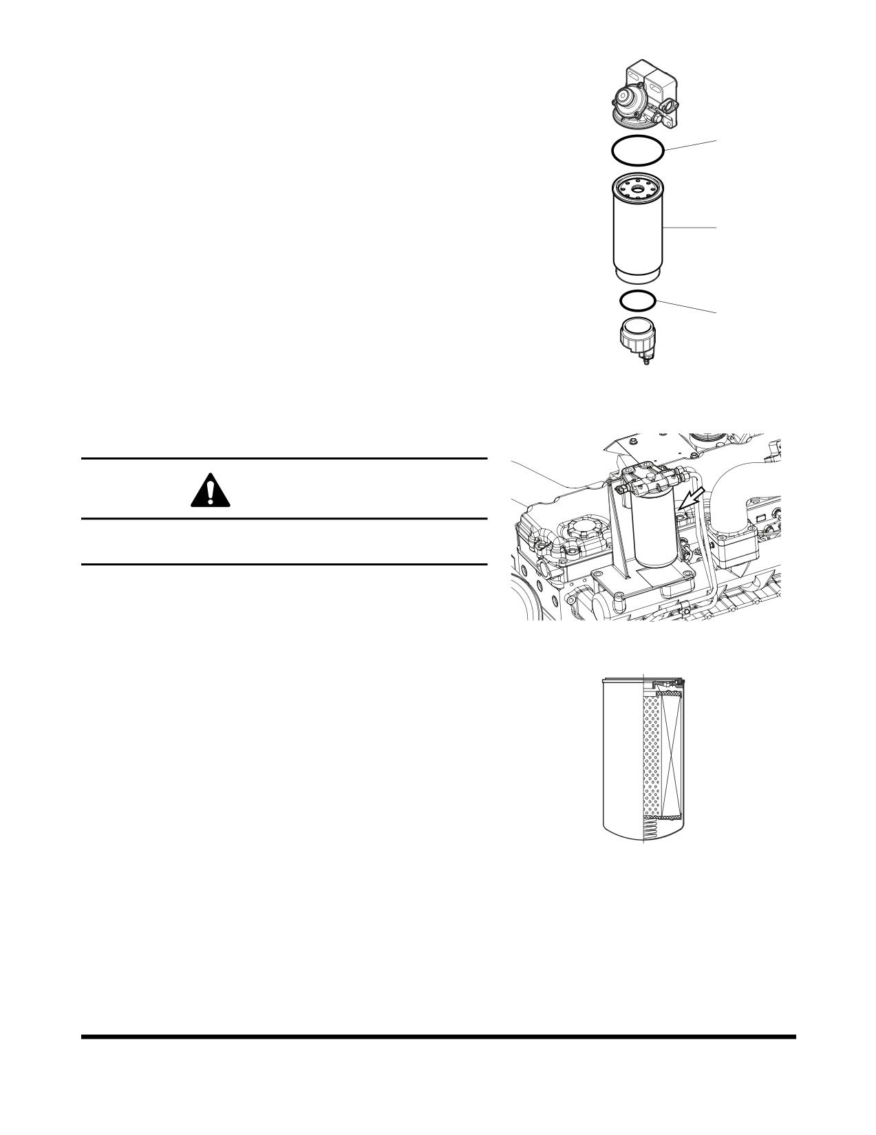
5.
Coat surface of packing (2, Figure 66) with fuel on new
cartridge (1).
6.
Tighten the cartridge by hand until the packing comes
into contact with the surface of the filter housing head.
7.
When it reach the surface, tighten the cartridge about
2
3/4 of a turn more.
8.
Coat surface of seal
(3, Figure
66) with fuel, and
tighten the bowl with tool.
1
3
FG000428
Figure 66
Change Fuel Filter
WARNING!
Exchange filter after waiting for engine to cool. Be
careful of fire hazards. Do not smoke.
1.
Locate fuel filter inside engine compartment.
2.
Position a small container under fuel filter.
FG006315
Figure 67
3.
Unscrew fuel filter from head assembly. Discard fuel
filter.
NOTE:
Dispose of drained fluids according to local
regulations.
4.
After cleaning filter head, install new fuel filter. Screw
filter on head until gasket contacts head, and turn filter
1/2 turn more with a filter wrench.
NOTE:
Coat fuel filter gasket with fuel.
NOTE:
Fill fuel filter with clean fuel. This will help
FG000478
reduce fuel system priming.
Figure 68
Inspection, Maintenance and Adjustment
OP000484
4-42
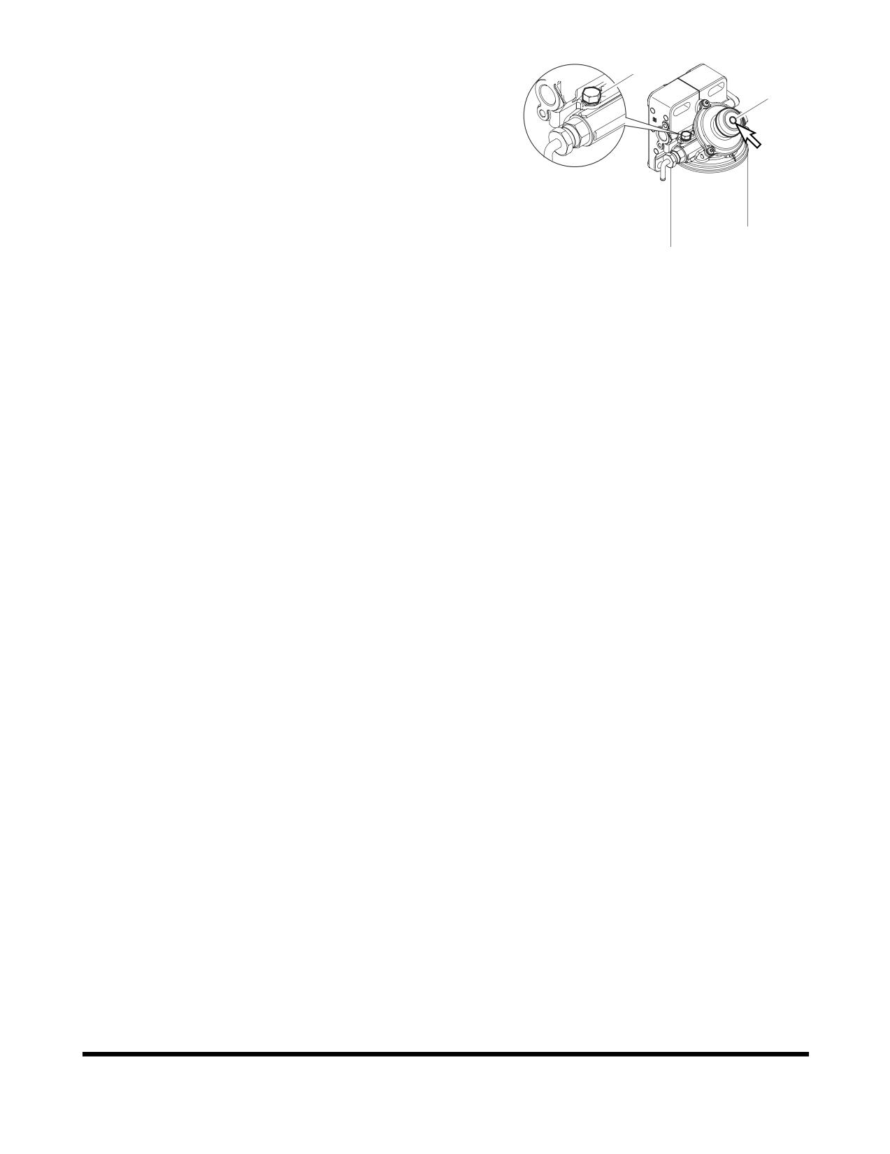
Fuel System Priming
1
If air remains in the fuel inlet line to the engine, it may
2
cause the engine to run in an abnormal condition. Air may
impact the starting capability of the engine, and may also
result in surging engine speeds.
If the machine happens to have run out of fuel, or if the
fuel filter has been replaced, air may need to be bleed
using the following procedure:
1.
Shut down engine.
FG000431
2.
Loosen plug (1, Figure 69) on the fuel prefilter head.
Figure 69
3.
Pump the hand operated primer pump (2, Figure 69)
on the fuel prefilter. Pump primer until fuel is present
at plug hole in fuel prefilter head.
4.
Tighten plug (1, Figure 69) in fuel prefilter head.
5.
Continue to pump primer pump until a strong
resistance is felt.
6.
Start engine and look for signs of leaks.
7.
Repeat procedure if necessary.
OP000484
Inspection, Maintenance and Adjustment
4-43
1,000 HOUR / 6 MONTH
SERVICE
Perform All Daily, 50, 250 and 500 Hour
Service Checks
Grease Swing Reduction Device
1.
Position the machine on firm, level ground. Lower the
front attachment to the ground and shut down engine.
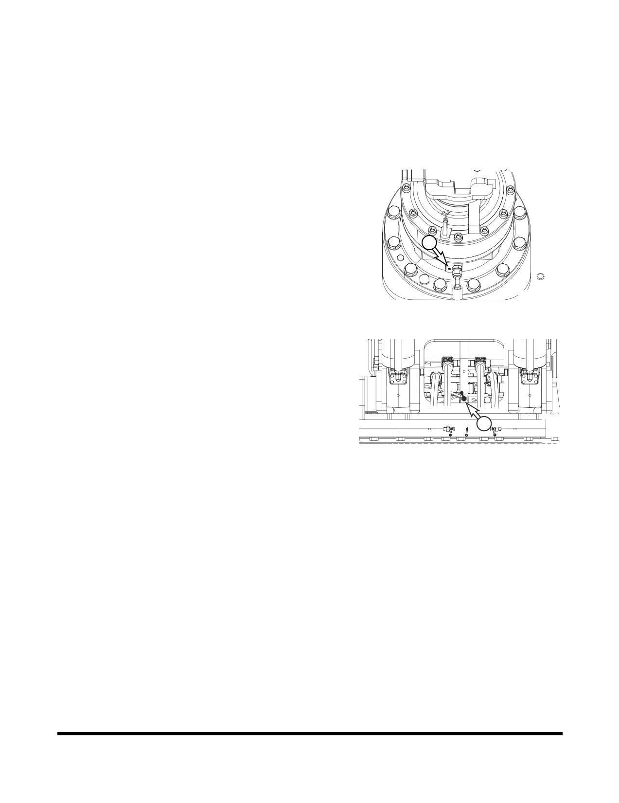
2.
Remove air vent plug
(1, Figure
70) from swing
reduction device.
1
FG006963
Figure 70
3.
Press grease fitting and inject grease with the grease
gun on the marked point (2, Figure 71).
4.
Install air vent plug (1, Figure 70) in swing reduction
device.
2
FG006964
Figure 71
Inspection, Maintenance and Adjustment
OP000484
4-44
Change Hydraulic Oil Return Filter
02/05 [MO] 11:30
NOTE:
Change hydraulic oil return filter after first 250 hours
of operation or rebuild, and every
1,000 hours
thereafter.
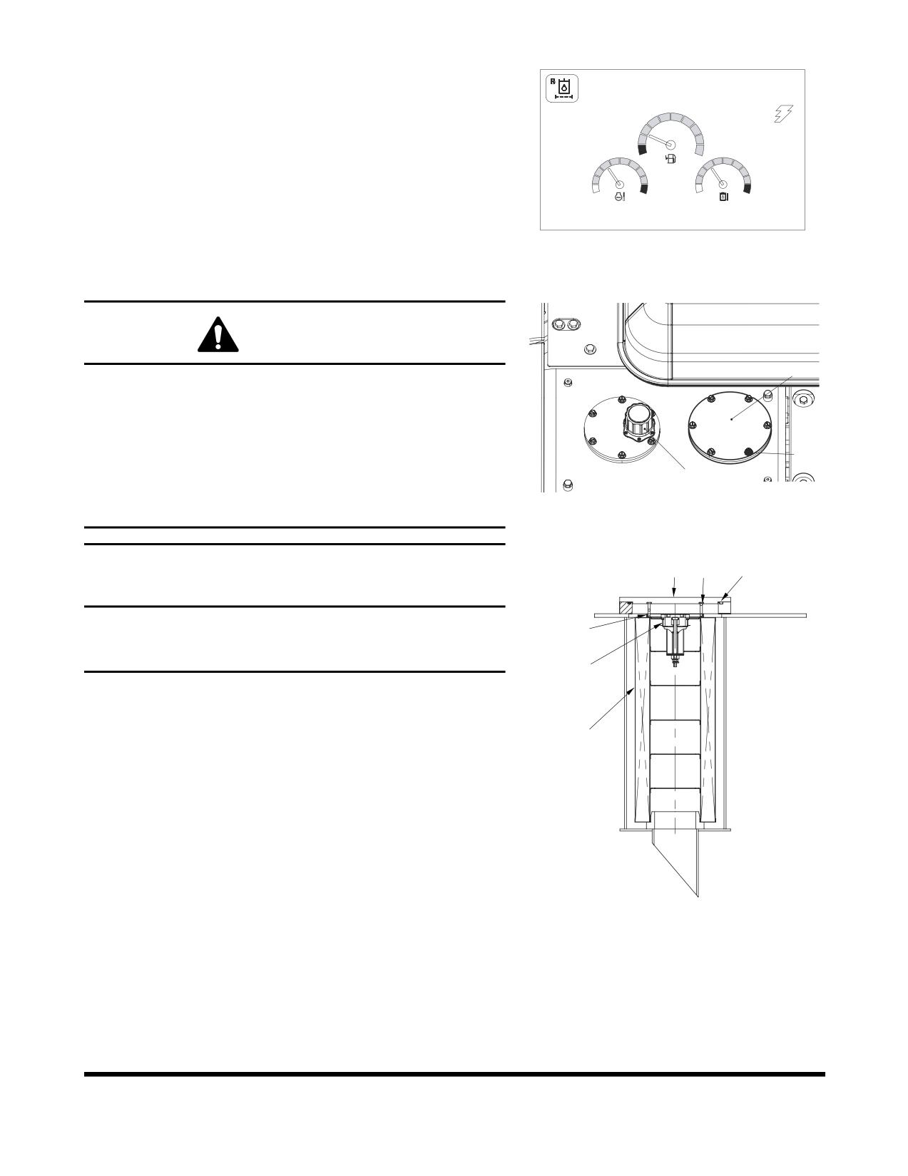
NOTE:
If return filter clogged warning light (Figure 72) on
E
F
instrument panel comes "ON" the return filter must be
serviced.
C
H
C
H
E/G SPEED 1700 RPM
FG000760
Figure 72
WARNING!
3
The hydraulic oil will be hot after normal machine
operation. Allow the system to cool before attempting to
service any of the hydraulic components.
The hydraulic tank is pressurized. Loosen the hydraulic
2
breather cap slightly to allow the pressurized air to vent.
After the pressure has been released, it is safe to
1
FG006965
remove either the fill cap or service covers or drain
water from the tank.
Figure 73
3
4
6
IMPORTANT
Make sure to clean any dirt or water from the top of the
7
hydraulic tank, especially around the fill port and filter
ports.
5
1.
Position the machine on firm, level ground. Lower the
front attachment to the ground and shut down engine.
8
2.
Loosen the breather cap
(1, Figure
73) slightly to
release the internal pressure.
3.
Remove bolts
(2, Figure
73) and service cover
(3).
Remove spring (4), valve (5) O-ring (6), and bypass
strainer (7), and then filter
(8).
4.
Remove filter and discard.
NOTE:
Used filter should always be disposed of
according to local regulations.
FG000761
5.
Install new filter and a new O-ring. Install bypass
Figure 74
strainer, valve and spring. Install service cover plate.
6.
Tighten the breather cap (1, Figure 73).
7.
Run engine for ten minutes at low idle to purge air
from circuit.
8.
Check level in hydraulic oil tank (See page 4-15). Add
oil if necessary.
OP000484
Inspection, Maintenance and Adjustment
4-45
Change Pilot Filter
02/05 [MO] 11:30
NOTE:
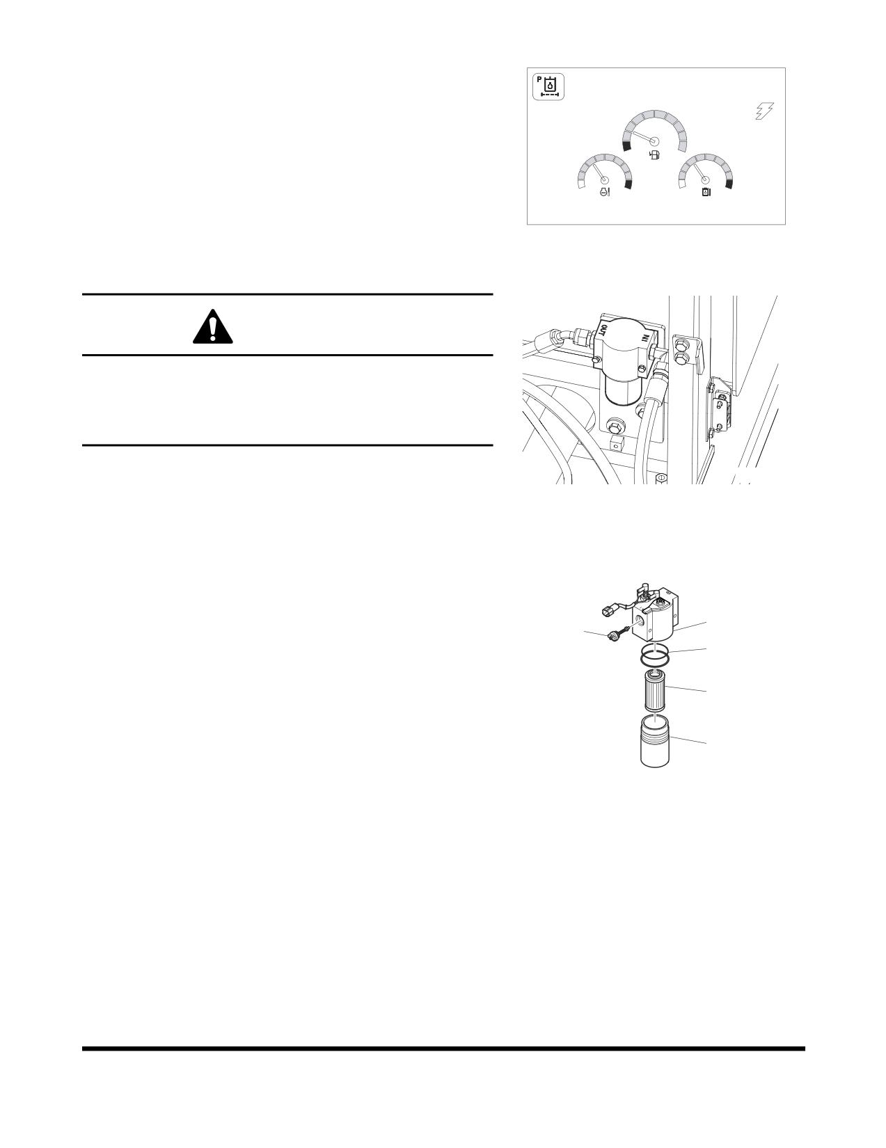
Change pilot filter after first 250 hours of operation or
rebuild, and every 1,000 hours thereafter.
NOTE:
If pilot filter clogged warning light (Figure 75) on
instrument panel comes "ON" the pilot filter must be
E
F
serviced.
C
H
C
H
E/G SPEED 1700 RPM
FG000763
Figure 75
WARNING!
The hydraulic oil will be hot after normal machine
operation.
Allow the system to cool down before changing pilot
filter.
1.
Position the machine on firm, level ground. Lower the
FG006966
front attachment to the ground and shut down engine.
Figure 76
2.
Loosen the breather cap
(1, Figure
73) slightly to
release the internal pressure.
3.
Locate pilot system filter assembly. See Figure 76.
4.
Unscrew canister (5, Figure 77) and remove O-ring (3)
and filter cartridge (4).
1
NOTE:
The canister will be filled with oil. Use caution
2
when removing this assembly.
3
5.
Insert a new filter cartridge and O-ring. Apply a small
amount of oil around the entire O-ring and install the
4
canister assembly onto the filter head (1, Figure 77).
NOTE:
Used filter should always be disposed of
according to local regulations.
5
FG000323
6.
After changing pilot filter, vent air from pump and
Figure 77
check level of hydraulic oil tank.
Inspection, Maintenance and Adjustment
OP000484
4-46
Change Oil in Travel Reduction Device
(One on Each Side of Unit)
3
WARNING!
1
The gear oil is very hot after the machine has been
operating. Shut all systems down and allow them to
2
cool. Before fully removing any motor case, inspection
port plug, etc., loosen the plug slightly to allow
FG006955
pressurized air to escape.
Figure 78
NOTE:
Drain oil after first 250 hours of operation or rebuild,
and every 1,000 hours thereafter.
1.
Make sure that the machine is on firm, level ground.
2.
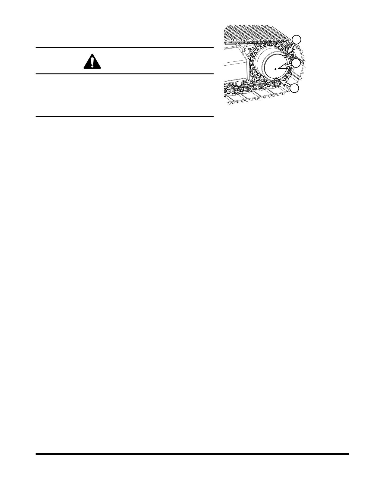
Rotate the track until ports (1 thru 3, Figure 78) are in
their proper positions as shown.
3.
Place a container under drain plug (2, Figure 78) and
remove plugs (1 thru 3) to drain the travel reduction
gear oil.
NOTE:
Dispose of drained fluids according to local
regulations.
4.
Install drain plug
(2, Figure
78). Refill the travel
reduction gear case with fluid through fill port (3) until
the fluid level is at port (1). Install level plug (1) and fill
plug (3).
NOTE:
See “Fluid Capacities” on page 4-8. for
capacity.
5.
Repeat this procedure on the other travel reduction
device.
OP000484
Inspection, Maintenance and Adjustment
4-47
Change Air-Conditioning Outer Filter
The unit is equipped with an air filtration system which filters
out dirt and dust particles from air being circulated into
operator's cabin. This filter should be cleaned out.
NOTE:
In the event that the unit is being operated in a dusty
environment, the cleaning and replacement should
be performed more frequently. If filter is damaged,
replace damaged filter with a new one.
WARNING!
All service and inspection of air-conditioning system
should be performed with the starter switch in the "O"
(OFF) position.
NOTE:
All right and left call outs are based on the operator
being seated in the operator's seat facing the front.
1.
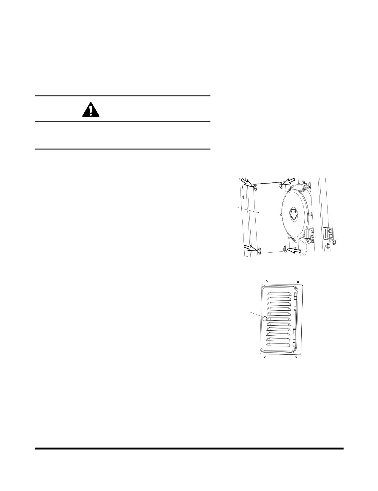
Open the door in the left front of the machine, then
remove four wing bolts and washers, and access cover
(1, Figure 79).
1
Donaldson.
FG000440
Figure 79
2.
Open the cover by unscrewing the knob (1, Figure 80)
in the rear of the cabin.
1
FG000441
Figure 80
Inspection, Maintenance and Adjustment
OP000484
4-48
3.
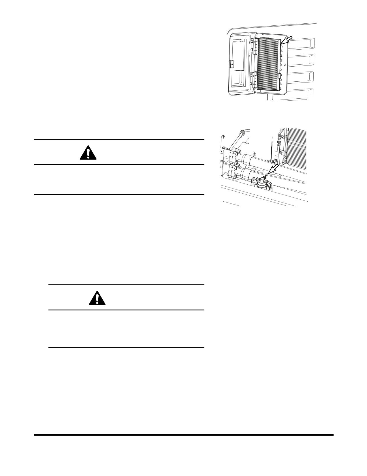
Remove filter (Figure 81) and replace with new one.
4.
Reassemble in reverse order.
FG000342
Figure 81
Check Air Conditioner Refrigerant
WARNING!
Mixing of tobacco smoke and freon is deadly.
Do not smoke while servicing or recharging
air-conditioning system.
1.
Run engine at about 1800 rpm. Operate for a minimum
FG006968
of ten minutes to stabilize the system.
Figure 82
2.
Press the "HI" fan speed switch to set maximum air
flow.
3.
Put the temperature control switch in maximum cooling
position.
4.
Press the "Internal Air Circulation" switch.
5.
Compare the flow of bubbles in the sight glass of
receiver dryer with the drawings in the following table.
CAUTION!
Overfilling refrigerant may cause dangerous
high-pressure and poor cooling action; and low
refrigerant level may cause compressor damage.
Always maintain refrigerant at normal level.
OP000484
Inspection, Maintenance and Adjustment
4-49
Amount of
Appearance of the Sight Glass
Solutions
Refrigerant
Almost clear.
Normal
Any bubbles disappear.
Charge or withdraw the system
with the correct amount of
High
No bubbles are seen.
HFC-134a refrigerant.
Low
A flow of bubbles is visible.
Check and Adjust Engine **
Contact your nearest DOOSAN dealer.
Engine dealer for checking and adjusting the following items:
•
Engine Compression Pressure.
•
Injection Pressure.
•
Injection Timing.
Inspection, Maintenance and Adjustment
OP000484
4-50
2,000 HOUR / YEARLY
SERVICE
Perform All Daily, 50, 250, 500 and 1,000
Hour Service Checks
Change Swing Reduction Device Oil
2
NOTE:
Change swing reduction device oil after first
250
hours of operation or rebuild and every 2,000 hours
thereafter.
1
WARNING!
The gear oil is very hot after the machine has been
FG006969
operating. Shut all systems down and allow them to
cool.
Figure 83
1.
Set a container under excavator.
2.
Remove cap (3, Figure 84) and install hose (4) to drain
the swing reduction device oil.
NOTE:
Dispose of drained fluids according to local
regulations.
3.
After draining oil, remove hose and install cap.
3
4
FG006970
Figure 84
4.
Remove breather/fill cap (2, Figure 83) and add oil to
"H" mark on dipstick (1).
FG000419
Figure 85
OP000484
Inspection, Maintenance and Adjustment
4-51
Change Outer and Inner Air Cleaner
Elements
3
WARNING!
Never clean or attempt to remove the air cleaner
element if the engine is running.
NOTE:
Change outer element after cleaning 5 times or every
FG000414
2,000 hours of service.
Figure 86
NOTE:
Change inner element whenever a new outer
element is installed.
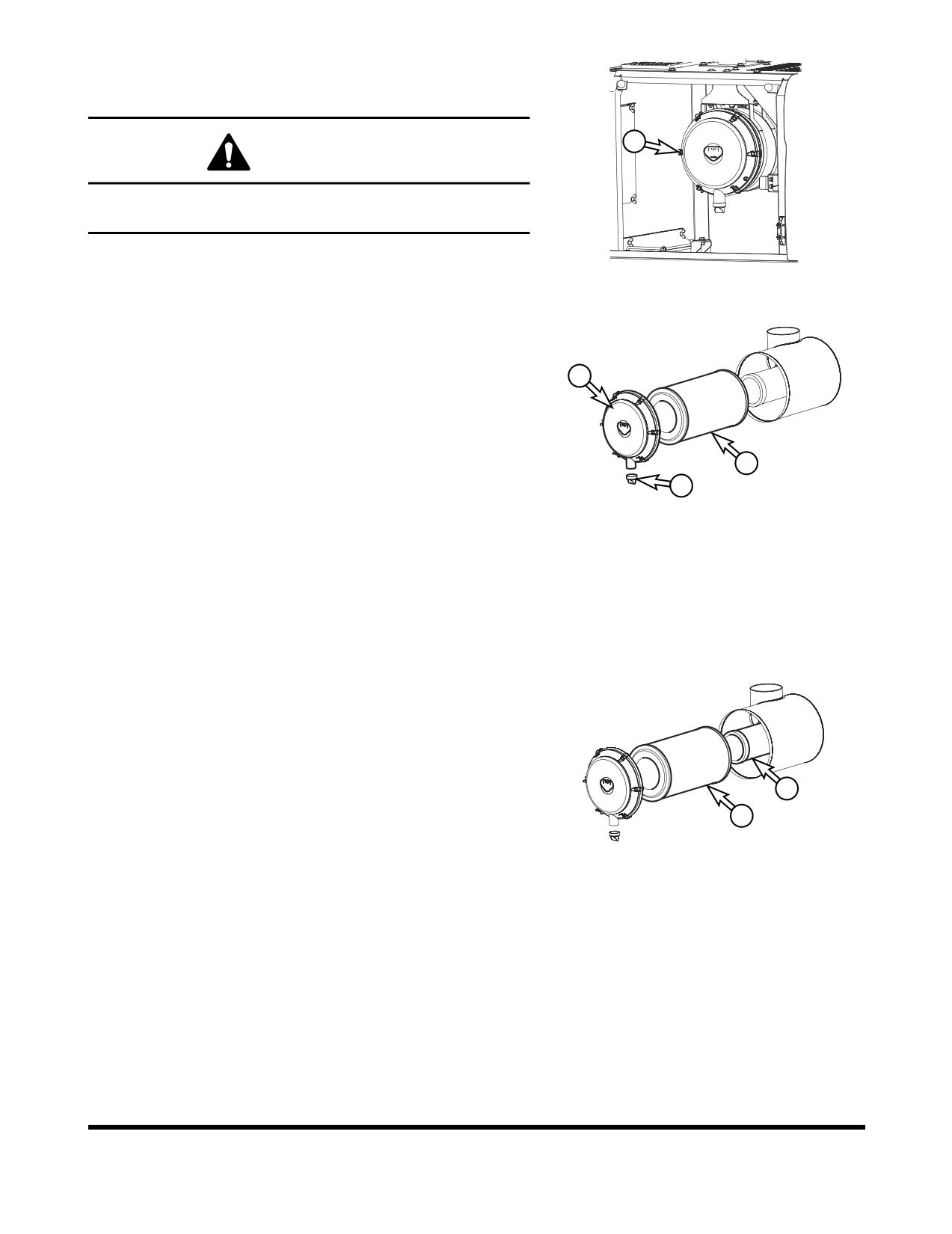
If there is clogged filter signal on the gauge panel, use the
2
following procedure.
1.
Open the access door at the rear of the cabin.
2.
Remove the evacuator valve
(1, Figure
87) and air
cleaner cover (2).
4
NOTE:
Inspect evacuator valve seal lips for wear or
1
damage. Replace valve if necessary. Install
FG000425
evacuator valve with lips parallel to the cover.
Figure 87
3.
Remove outer filter (4, Figure 87) from the air cleaner
housing.
4.
Clean the air cleaner cover and the inside of the air
cleaner housing.
5.
Remove inner filter (5, Figure 88).
6.
Clean out inside of air cleaner housing. Do not use
compressed air to blow out housing.
7.
Install new inner filter. Do not clean and reuse inner
element.
8.
Install new outer filter.
9.
Install air cleaner cover and evacuator valve.
5
NOTE:
Make sure that all gaskets and cover are
4
properly installed and seated.
FG000426
Figure 88
Inspection, Maintenance and Adjustment
OP000484
4-52
Change Radiator Coolant
WARNING!
Allow the engine to cool before releasing the radiator
cap. Make sure to loosen the cap slowly to release any
remaining pressure.
Radiator cleaning is performed while the engine is
running. Take extreme caution when working on or near
ARO1760L
a running engine. Make sure to lock out and tag the
Figure 89
controls notifying personnel that service work is being
performed.
Do not remove the radiator cap unless it is required.
Observe the coolant level in the coolant recovery tank.
1.
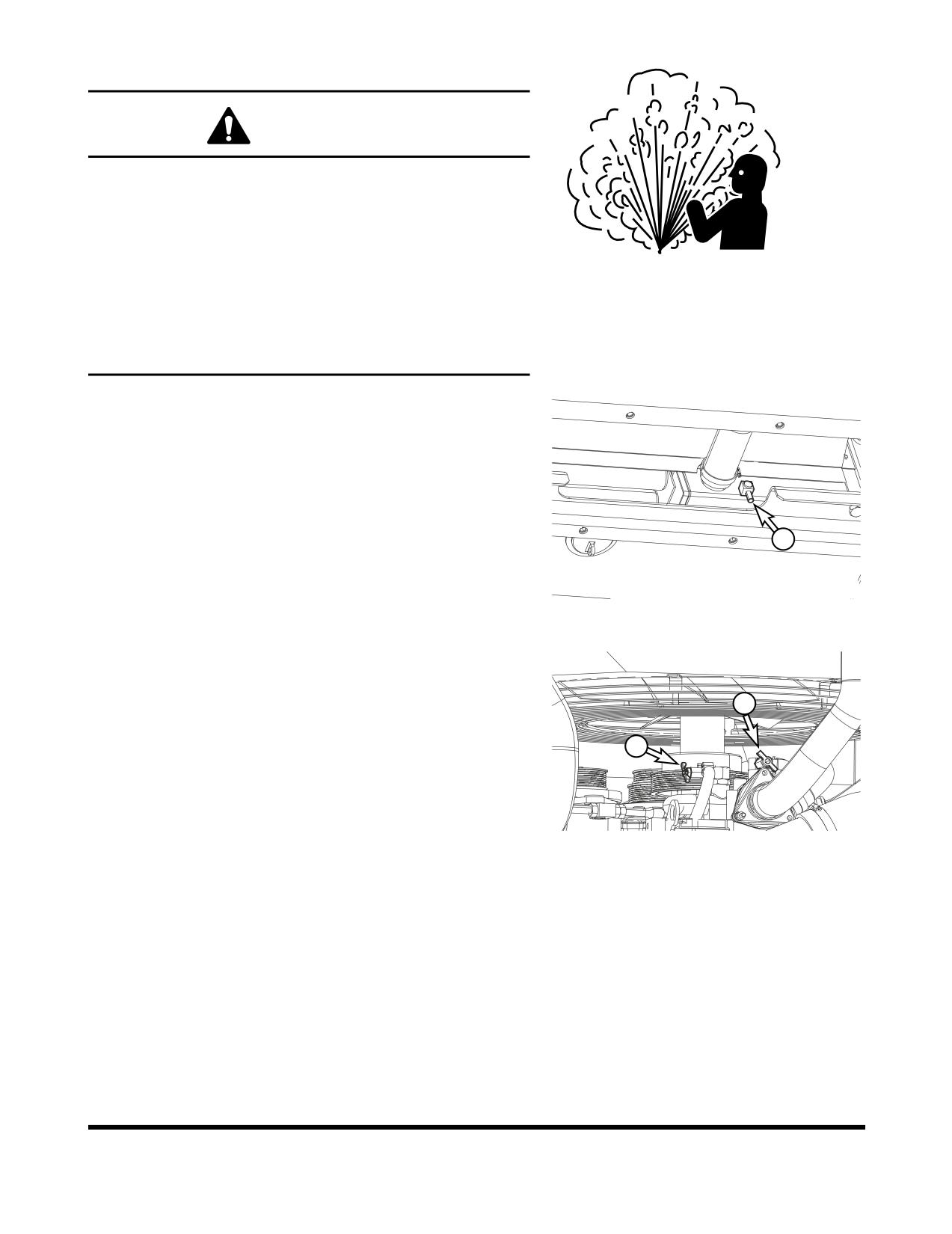
Slowly open the radiator cap to allow any pressure to
escape.
2.
Place a container under the radiator and open the
drain valve (2, Figure 90).
NOTE:
Dispose of drained fluids according to local
regulations.
2
FG006319
Figure 90
3.
Open heater shutoff valves
(3 and
4, Figure
91) to
allow coolant to drain from heater core.
4
3
FG006320
Figure 91
OP000484
Inspection, Maintenance and Adjustment
4-53