1t-3.5t R Series Internal Combustion Counterbalanced Forklift Truck. Manual - part 21
 

  Index      Engines     HANGCHA 1t-3.5t R Series Internal Combustion Counterbalanced Forklift Truck - manual 2011 year


Search            


Content   ..  19  20  21  22   ..


1t-3.5t R Series Internal Combustion Counterbalanced Forklift Truck. Manual - part 21


80 

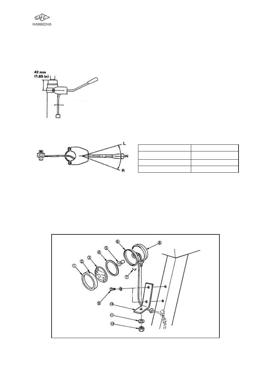
TURN SIGNAL LAMP SWITCH 
REMOVAL 
1. Remove assembled instrument. 
2. Remove bolt,disconnect wiring terminal。 
3. Fixing sequence is opposite to removing sequence. 


After installing turn signal lamp switch ,insure the distance between turn signal lamp 
switch and top of steering column is 42mm. 


Location of switch   

Junction point       

1-3 

No continuity   

1-2 

 
Front headlight 
Disassembly   
1.Remove securing nuts of the big-little lamp. 
2.Take apart the wiring connector. 
3.    Remove bolt、lens, then replace faulty   
bulb with new one. 
4. Assembly is the opposite procedures.   


Turning light switch 

Turning column 


81 

Front combination lamp 
Disassembly and assembly  
 
1.Remove fixing bolt of bracket. 
2.Disconnect the wiring connector. 
3.Remove bolt、astigmatism glass, then replace faulty bulb with new one. 
4. Assembly is the opposite procedures.   


REAR COMBINATION LAMP 
1.Remove fixing bolt of bracket. 
2.Disconnect the wiring connector. 
3.Remove bolt、astigmatism glass, then replace faulty bulb with new one. 
4. Assembly is the opposite procedures.   
Instrument, sensor and relay 
Inspect  whether  relay  circuit  is  on,  connect  or  disconnect  coil  with  proper 
voltage(supplied  by  battery),  and  then  use  multimeter(with  ohm)  to  check  whether 
contactor is on.   
 
Disassembly and installation 
Combination meter assembly 
1.    Remove  4  fixed  bolt  from  meter  crust.  Notice  that  when  installing  and 

removing  ,please  make  instrument  surface  tilt  an  angle  to  avoid  damaging  the 
screw thread of    fixed parts on truck.   

2.    Take out wiring harness from sleeve, and then instrument can be brought out. 
3.    There is transparent plastic cover to cover, so it can prevent dust and water, and 
it is fixed by 6 plastic clip buckle, please press down plastic buckles lightly to take out 
plastic cover when removing.   
4.    To install, reverse removal procedures.   


82 


1 .Fastening bolt of meter shell      2. Flameout lever      3. Rear work light switch 
 
Fuel meter, temperature meter, hour meter and alarm lamp 
1、 Remove fastening bolt on meter plate, then separate meter plate and meter shell. 
2、 Remove fastening bolt on front protect hood, then separate front protect hood and 

meter plate. 

3、 Remove meter plate 
4、 Remove fastening bolt from PC plate, then remove meters. 
5、 Remove  alarm  lamp  from  PC  plate  (all  alarm  lamp  can  be  removed  from 

compound meter individually). 

6、 To install, reverse disassembly procedures. 


Key (start) switch 
1、Remove combination meter. 
2、Disconnect connector of wring. 
3、Remove nuts, washers, spacers and instrument plate. 
4、To install, reverse removal procedures.   
Adjust ledge of switch to proper length when installing. 
Inspect   
Use multimeter (with ohm) to check key switch wether it is on at each position. 
 

Meter shell 

Fastening  bolt  of  front 
protect hood 

Front 

protect 

hood 

Meter board 

Meter plate 

Fastening  bolt  of 
meter board 


83 

Switch position   

Terminal   

OFF 

OFF 

ON 

B1-B2-Acc    on 

START 

B1-B2-Acc-C-R2    on 


              Location  of   

switch   

Terminal 

OFF 

ON 

START 

1(B2) 


2(Acc) 


3(C) 


4(R2) 


REVERSE BUZZER 
1.Remove  the  wiring  terminal , then 
unscrew the bolt. 
2.To install, reverse removal procedure
 
HORN   
REMOVAL AND INSTALLATION 
1.Disconnect horn harness connector. 
2.Remove bolt and horn. 
3.To install, reverse removal procedure. 


Content   ..  19  20  21  22   ..