1t-3.5t R Series Internal Combustion Counterbalanced Forklift Truck. Manual - part 15
 

  Index      Engines     HANGCHA 1t-3.5t R Series Internal Combustion Counterbalanced Forklift Truck - manual 2011 year


Search            


Content   ..  13  14  15  16   ..


1t-3.5t R Series Internal Combustion Counterbalanced Forklift Truck. Manual - part 15


56 


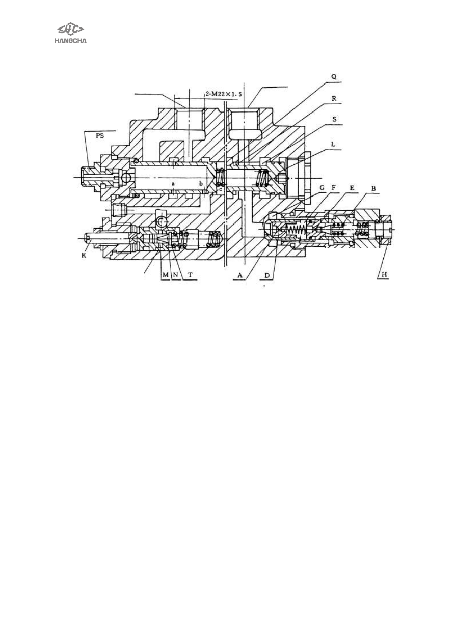
Fig. 7-5 


4.2 Adjusting the pressure of the main relieve valve 

The pressure of the main relieve valve is all ready adjusted in the factory, and it 

can’t be adjusted generally. The following is an example of 3t truck to specify how to 
adjust the pressure. 
(1). Put 125 percent of the rated load (3750kg) on the forklift stable. 
(2).Step the accelerated pedal to the end, control the lift pole, if the forklift can get the 

height of 

0mm-300mm, the main relieve valve is all right. Otherwise, adjust it as step (3). 
(3).If the forklift can’t work, enhance the pressure main relieve valve, remove the front 

soleplate, loosen the tightening nut of the main relieve valve, screw the adjusting 
nut clockwise to enhance the pressure of the main relieve valve. If the height of lift 
is higher than 300mm, screw the adjust nut anti-clockwise to reduce the pressure. 

(4).Step  the  accelerated  pedal  to  the  end  to  make  the  forklift  in  the  height  range  of 

0mm-300mm. Otherwise, adjust it as step (3). 

(5).Retighten the tightening nut, fix it on the front soleplate. 
Warning: 
·

The load should be put stably. 

·Don’t adjust if the pressure is already adjusted correctly. 
4.3 Operation of tilt lock valve 

Tilting  lock  valve  is  fitted  by  lock-self  valve  to  prevent  vibration  owing  to  back 

pressure  inside  tilt  cylinder  and  avoid  casualty  because  of  miss-operation.   
According to common structure, it can operate tilt spool to tilt forward after engine is 

To redirector 

Oil-return   

Oil-input 

Main safety valve 

Flow divide safety valve 


57 

off,  but  using  the  tilt  lock  valve,  when  engine  is  off,  it  cannot  tilt  mast  forward  even 
push the lever of operation valve, the structure is shown as Fig. 7-6. 
Connector of valve body: ―A‖,―B‖ connects separately with frond and rear house of tilt 
cylinder piston. When pulling out spool, high pressure oil (

P) enters connector ―A‖, oil 

in rear house returns to oil tank (T), in this time mast is in tilting backward. 

When pulling tilting spool, high pressure oil enters connector ―B‖, by high pressure 

oil, lock valve in spool works to make ―A‖ to connect with low pressure. When engine 
is  off  or  stop,  lock  valve  in  spool  cannot  work  without  high  pressure  oil,  so  that 
connector ―A‖ can not connect low pressure line and mast cannot tilt forward, also there 
is not back pressure in tilt cylinder. 


Fig. 7-6


5. Hydraulic piping 

The high pressure oil from main pump goes to control valve and divide it to two 

parts by priority valve inside control valve: one of them preferentially goes to steering 
gear  control  steering  cylinder,  excess  part  goes  to  lifting  cylinder  or  tilting  cylinder. 
When lifting and tilting spool is in neutral, high pressure oil return oil tank directly from 
pass way. When pulling lifting spool, high pressure oil goes by throttle valve and then 
push  piston  rod  under  lifting  cylinder  piston.  When  pushing  lifting  spool,  it  is  that 
bottom  of  lifting  cylinder  piston  connects  with  low  pressure  line  and  then  piston  rod 
drops by deadweight and weight of cargo. In this time, oil from lifting cylinder goes by 
unidirectional speed limiting valve so as to control the falling speed. When operating 
tilting  spool,  high  pressure  oil  goes  to  front  house  of  tilting  cylinder  and  another 
connects with low pressure line so as to make mast tilt forward or backward. 
The cut off valve is used under right lifting cylinder, its function is to prevent goods 
falling suddenly when oil pipe is busting. 
 

Fig.9-6 


58 


Fig. 7-7 Schematic figure of hydraulic system 


59 

Ⅷ.Lifting system 

1. Assemble debugging data 

Debugging data 


Double mast and triple mast 

Mast type 

Standard type and 

lifting height of 2~4 

meter 

Lifting height 

>4~5 meter 

Lifting height 

> 5~6 meter 

Mast tilt 

angle 

Forward 

6° 

6° 

3° 

Backward 

12° 

6° 

6° 

Fork arm carrier roller 

Adopt combination roller and side roller 

  if rated capacity is less than 3 .5t. 

 
Inspection and adjustment   

Place   

Assembly clearance 

(mm) 

Repair clearance(mm) 

Mast to lift roller 

0.1~0.8 

0.2~1 

Shims   

0.5,1.0,2.0 

Mast to back up metal 

0.1~0.8 

0.2~1 

Shims 

0.5,1.0,2.0 

Inner  mast  to  carriage 
side roller 

0.1~0.6 

0.2~1 

Shims 

0.5,1.0,1.5 

Lift chain deflection 

25~30 mm 

 
Tightening torque   

Place 

Model or Lifting capacity 

Lift chain lock nut 

1-1.8t 

193-257(M16) 

2~3.5t 

245-314(M20) 

Mast support cap blot 

1-1.8t 

124-165(M14) 

2~3.5t 

176-216(M18) 

Tilt cylinder lock nut 

1-1.8t 

89-118(M14) 

2~3.5t 

Lift cylinder bolt(top) 

1-1.8t 

76-107(M12) 

2~3.5t 

Lift cylinder bolt(bottom) 

1-1.8t 

22-30(M8) 

2~3.5t 

Lift cylinder fixing 

bolt(cylinder light bolt) 

1-1.8t 

76-107(M12) 

2~3.5t 

 
Basic model mast weight 

Model(truck) 

1t 

1.5 t 

1.8t 

2t 

2.5t 

3t 

3.5t 

Weight(mast) kg 

531 

531 

540 

575 

644 

721 

820 


Content   ..  13  14  15  16   ..