Perkins 402D, 403D, 404D Industrial Engine. Manual - part 6
 

  Index      Engines     Perkins 402D, 403D, 404D Industrial Engine - service manual


Search            


Content   ..  4  5  6  7   ..


Perkins 402D, 403D, 404D Industrial Engine. Manual - part 6


SEBU8311-01

23

Product Information Section

Product Identification Information

Product Identification

Information

i02643641

Engine Identification


Perkins engines are identified by a serial number.

This number is shown on a serial number plate that

is mounted above the fuel injection pump on the right

hand side of the engine block.

An example of an engine number is

GP*****U000001M.

GP

_________________________________________

Type of engine

U

____________________________

Built in the United Kingdom

*****

______________________

The list number of the engine

000001

___________________________

Engine Serial Number

M

____________________________________

Year of Manufacture

Perkins dealers or Perkins distributors need all of

these numbers in order to determine the components

that were included with the engine. This permits

accurate identification of replacement part numbers.

i02157258

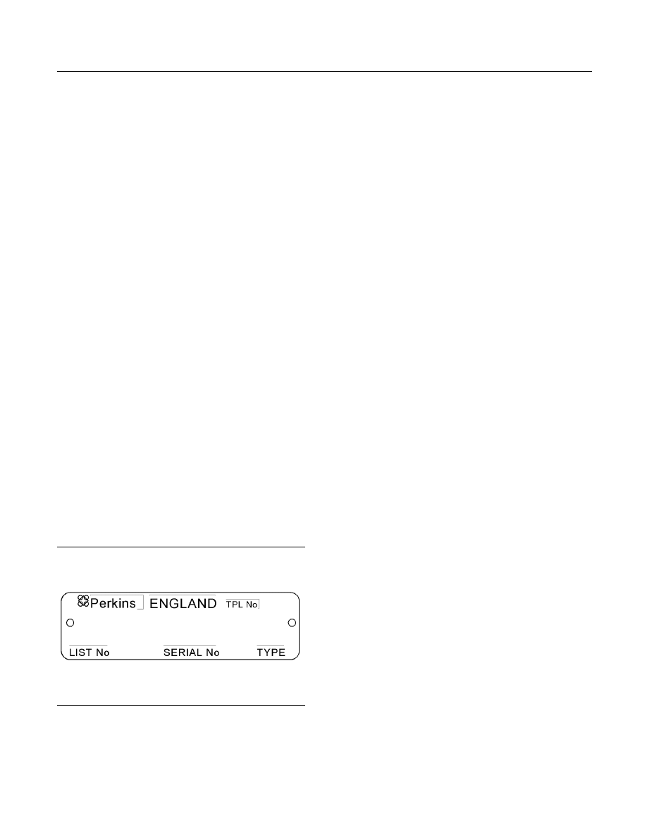
Serial Number Plate


g01094203

Illustration 23
Typical serial number plate

The Serial Number Plate is located above the fuel

injection pump on the right side of the cylinder block.

The following information is stamped on the Serial

Number Plate: Engine serial number, Model, and

Arrangement number.

i02164876

Reference Numbers


Information for the following items may be needed to

order parts. Locate the information for your engine.

Record the information in the appropriate space.

Make a copy of this list for a record. Keep the

information for future reference.

Record for Reference

Engine Model

_______________________________________________

Engine Serial number

_____________________________________

Engine Low Idle rpm

______________________________________

Engine Full Load rpm

_____________________________________

Primary Fuel Filter

_________________________________________

Water Separator Element

________________________________

Secondary Fuel Filter Element

__________________________

Lubrication Oil Filter Element

___________________________

Auxiliary Oil Filter Element

_______________________________

Total Lubrication System Capacity

_____________________

Total Cooling System Capacity

_________________________

Air Cleaner Element

_______________________________________

Fan Drive Belt

______________________________________________

Alternator Belt

______________________________________________

24

SEBU8311-01

Product Information Section

Product Identification Information

i02959144

Emissions Certification Film


g01478138

Illustration 24
Typical example

g01476654

Illustration 25

Typical example

Perkins Shibaura Engines Limited will supply the

fuel label with every engine. Refer to illustration

25. The equipment manufacturer must install the

label to the equipment. This is recommended by

Perkins Shibaura Engines Limited. The label must be

attached to the equipment near the fuel inlet. This

will comply with the EPA regulations. The equipment

manufacturer may install another fuel label. If another

fuel label is used, the equipment manufacturer must

send a drawing or a photo of the label to Perkins

Shibaura Engines Limited through the Perkins

Distributor. This will ensure compliance of the label.

SEBU8311-01

25

Operation Section

Lifting and Storage

Operation Section

Lifting and Storage

i02164186

Engine Lifting


g01097527

Illustration 26

NOTICE

Never bend the eyebolts and the brackets. Only load

the eyebolts and the brackets under tension. Remem-

ber that the capacity of an eyebolt is less as the angle

between the supporting members and the object be-

comes less than 90 degrees.

When it is necessary to remove a component at an

angle, only use a link bracket that is properly rated for

the weight.

Use a hoist to remove heavy components. Use

an adjustable lifting beam to lift the engine. All

supporting members (chains and cables) should be

parallel to each other. The chains and cables should

be perpendicular to the top of the object that is being

lifted.

Some removals require lifting the fixtures in order to

obtain correct balance and safety.

To remove the engine ONLY, use the lifting eyes that

are on the engine.

Lifting eyes are designed and installed for specific

engine arrangements. Alterations to the lifting eyes

and/or the engine make the lifting eyes and the lifting

fixtures obsolete. If alterations are made, ensure

that correct lifting devices are provided. Consult

your Perkins dealer or your Perkins distributor for

information regarding fixtures for correct engine

lifting.

i02593735

Engine Storage


If the engine will not be started for several weeks, the

lubricating oil will drain from the cylinder walls and

from the piston rings. Rust can form on the cylinder

walls. Rust on the cylinder walls will cause increased

engine wear and a reduction in engine service life.

Lubrication System

To help prevent excessive engine wear, use the

following guidelines:

Complete all of the lubrication recommendations that

are listed in this Operation and Maintenance Manual,

“Maintenance Interval Schedule” (Maintenance

Section).

If an engine is out of operation and if use of the engine

is not planned, special precautions should be made.

If the engine will be stored for more than one month,

a complete protection procedure is recommended.

Use the following guidelines :

Completely clean the outside of the engine.

Drain the fuel system completely and refill

the system with preservative fuel.

1772204

POWERPART Lay-Up 1 can be mixed with

the normal fuel in order to change the fuel into

preservative fuel.

If preservative fuel is not available, the fuel system

can be filled with normal fuel. This fuel must be

discarded at the end of the storage period together

with the fuel filter elements.

Operate the engine until the engine reaches normal

operating temperature. Stop any leaks from fuel,

lubricating oil or air systems. Stop the engine and

drain the lubricating oil from the oil pan.

26

SEBU8311-01

Operation Section

Lifting and Storage

Renew the canister(s) of the lubricating oil filter.

Fill the oil pan to the Full Mark on the engine oil

level gauge with new, clean lubricating oil. Add

1762811 POWERPART Lay-Up 2 to the oil in

order to protect the engine against corrosion. If

1762811 POWERPART Lay-Up 2 is not available,

use a preservative of the correct specification

instead of the lubricating oil. If a preservative is

used, this must be drained completely at the end of

the storage period and the oil pan must be refilled

to the correct level with normal lubricating oil.

Cooling System

To help prevent excessive engine wear, use the

following guidelines:

NOTICE

Do not drain the coolant while the engine is still hot and

the system is under pressure because dangerous hot

coolant can be discharged.

If freezing temperatures are expected, check the

cooling system for adequate protection against

freezing. Refer to this Operation and Maintenance

Manual, “Fluid Recommendations” (Maintenance

Section).

NOTICE

To prevent frost damage, ensure that all the coolant is

removed from the engine. This is important if the sys-

tem is drained after it has been flushed with water, or if

an antifreeze solution too weak to protect the system

from frost has been used.

g01298045

Illustration 27
Typical example

1. Ensure that the vehicle is on level ground.

2. Remove the filler cap of the cooling system.

3. Remove the drain plug (1) from the side of the

cylinder block in order to drain the engine. Ensure

that the drain hole is not restricted.

4. Open the tap or remove the drain plug at the

bottom of the radiator in order to drain the radiator.

If the radiator does not have a tap or a drain plug,

disconnect the hose at the bottom of the radiator.

5. Flush the cooling system with clean water.

6. Fit the drain plugs and the filler cap. Close the tap

or connect the radiator hose.

7. Fill the cooling system with an approved antifreeze

mixture because this gives protection against

corrosion.

Note: Certain corrosion inhibitors could cause

damage to some engine components. Contact the

Service Department of Perkins for advice.

8. Operate the engine for a short period in order to

circulate the lubricating oil and the coolant in the

engine.

9. Disconnect the battery. Put the battery into safe

storage in a fully charged condition. Before the

battery is put into storage, protect the terminals

against corrosion.

1734115 POWERPART

Lay-Up 3 can be used on the terminals.

10. Clean the crankcase breather if one is installed.

Seal the end of the pipe.

11. Remove the fuel injectors and spray

1762811

POWERPART Lay-Up 2 for one or two seconds

into each cylinder bore with the piston at BDC.

12. Slowly rotate the crankshaft for one complete

revolution and then replace the fuel injectors.

Induction System

Remove the air filter assembly. If necessary,

remove the pipes that are installed between

the air filter assembly and the turbocharger.

Spray

1762811 POWERPART Lay-Up 2 into the

turbocharger. The duration of the spray is printed

on the container. Seal the turbocharger with

waterproof tape.


Content   ..  4  5  6  7   ..