Perkins 402D, 403D, 404D Industrial Engine. Manual - part 4
 

  Index      Engines     Perkins 402D, 403D, 404D Industrial Engine - service manual


Search            


Content   ..  2  3  4  5   ..


Perkins 402D, 403D, 404D Industrial Engine. Manual - part 4


SEBU8311-01

15

Product Information Section

Model Views

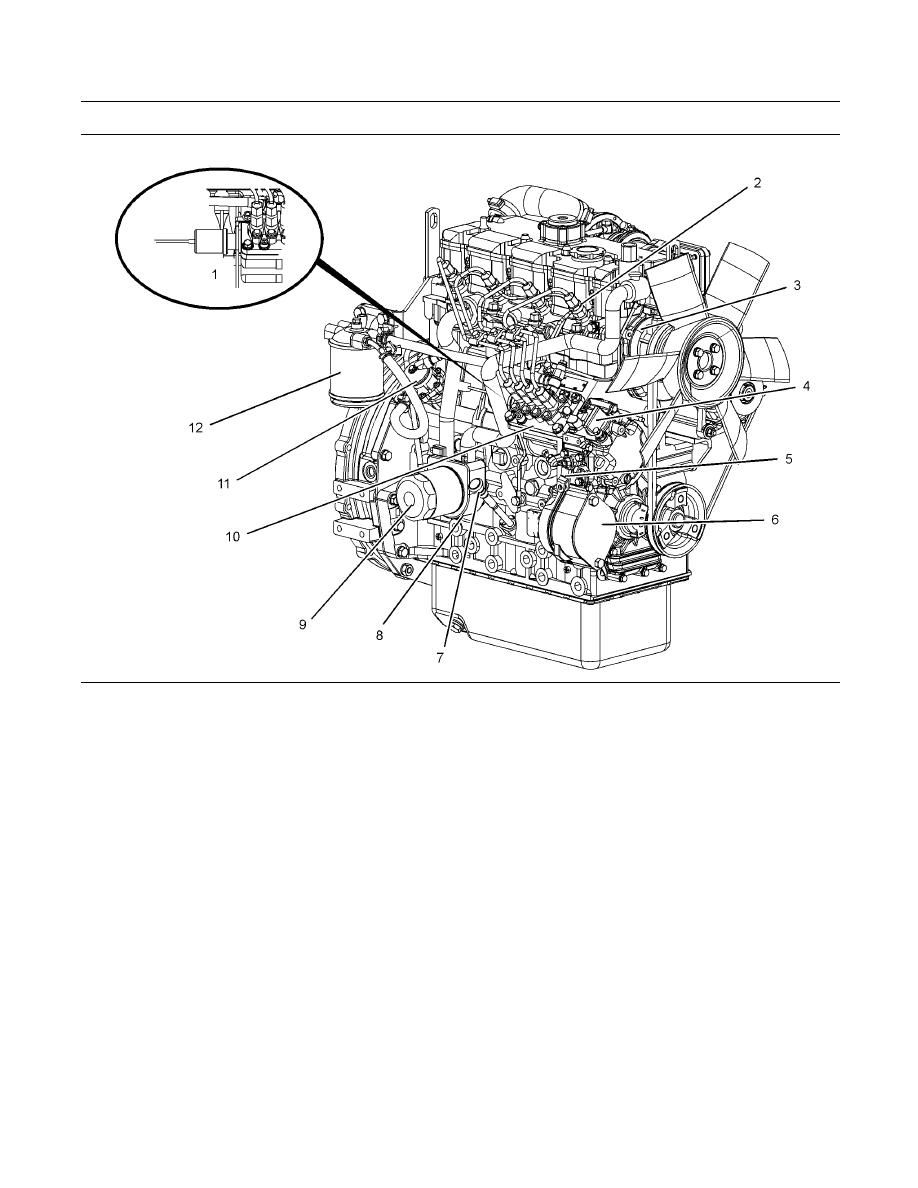
g01304893

Illustration 11

Front and right side view of the 404D-22T Engine
(1) Fuel shutoff solenoid
(2) Number one fuel injector
(3) Water pump
(4) Lower engine oil filler cap

(5) Throttle lever
(6) Cover plate for the accessory drive
(7) Engine oil level gauge
(8) Engine oil cooler

(9) Engine oil filter
(10) Fuel injection pump
(11) Transfer pump
(12) Fuel filter

16

SEBU8311-01

Product Information Section

Model Views

g01305224

Illustration 12

Front and left side view of the 404D-22T Engine
(13) Top engine oil filler cap
(14) Crankcase breather
(15) Rear Lifting eye
(16) Air inlet elbow
(17) Valve mechanism cover
(18) Turbocharger

(19) Water temperature regulator housing
(20) Starting motor solenoid
(21) Electric starting motor
(22) Alternator
(23) Engine oil pan
(24) Engine oil drain plug

(25) Fan drive belt
(26) Crankshaft pulley
(27) Coolant temperature switch
(28) Cooling fan

i02959055

Engine Description


The 400 series engines are indirect injection engines.

The engines are controlled with a mechanically

actuated fuel injection pump. The engine cylinders

are arranged in-line.

The cylinder head assembly has one inlet valve and

one exhaust valve for each cylinder. Each cylinder

valve has a single valve spring.

The pistons have two compression rings and an

oil control ring. It is important to ensure the correct

piston height so that the piston does not contact the

cylinder head. The correct piston height also ensures

efficient combustion of fuel that is necessary in order

to conform to requirements for emissions.

The crankshaft for a two cylinder engine has two

main bearing journals. The crankshaft for a three

cylinder engine has four main bearing journals. The

crankshaft for a four cylinder engine has five main

bearing journals. End play is controlled by the thrust

washers that are located on the rear main bearing.

SEBU8311-01

17

Product Information Section

Model Views

The timing gears are stamped with timing marks in

order to ensure the correct assembly of the gears.

When the No. 1 piston is at top center compression

stroke, the teeth that are stamped on the crankshaft

gear and the camshaft gear will be in alignment with

the idler gear.

The crankshaft gear turns the idler gear which then

turns the camshaft gear and the gear for the engine

oil pump.

The fuel injection pump is mounted in the cylinder

block. The fuel injection pump is operated by lobes

on the camshaft. The fuel transfer pump is located

on the right hand side of the cylinder block. The

fuel transfer pump is also operated by lobes on the

camshaft.

The fuel injection pump conforms to requirements

for emissions. If any adjustments to the fuel injection

pump timing and high idle are required you must

refer to your Perkins distributoror your Perkins

dealer. Some fuel injection pumps have mechanical

governors that control the engine rpm. Some fuel

injection pumps have a governor that is electrically

controlled.

A gerotor oil pump is located in the center of the idler

gear. The engine oil pump sends lubricating oil to the

main oil gallery through a pressure relief valve and an

engine oil filter. The rocker arms receive pressurized

oil through an externally located oil line that runs from

the main oil gallery to the cylinder head.

Coolant from the bottom of the radiator passes

through the belt driven centrifugal water pump. The

coolant is cooled by the radiator and the temperature

is regulated by a water temperature regulator.

Engine efficiency, efficiency of emission controls, and

engine performance depend on adherence to correct

operation and maintenance recommendations.

Engine performance and efficiency also depend on

the use of recommended fuels, lubrication oils, and

coolants. Refer to the Operation and Maintenance

Manual, “Maintenance Interval Schedule” for more

information on maintenance items.

Engine Specifications

Note: The front end of the engine is opposite the

flywheel end of the engine. The left and the right side

of the engine are determined from the flywheel end.

The No. 1 cylinder is the front cylinder.

18

SEBU8311-01

Product Information Section

Model Views

402D-05 Engine

g01108476

Illustration 13
(A) Exhaust valves
(B) Inlet valves

Table 1

402D-05 Engine Specifications

Maximum Operating
Speed (rpm)

3600 rpm

Cylinders and

Arrangement

In-Line two cylinder

Bore

67 mm (2.64 inch)

Stroke

72 mm (2.83 inch)

Displacement

0.507 L (30.939 in

3

)

Aspiration

NA

(1)

Compression Ratio

23.5:1

Firing Order

1-2

Rotation that is viewed
from the flywheel

Counterclockwise

Valve Lash Setting (Inlet)

0.20 mm (0.008 inch)

Valve Lash Setting

(Exhaust)

0.20 mm (0.008 inch)

Injection

Indirect

(1)

Naturally Aspirated

403D-07 Engine

g00852304

Illustration 14
(A) Exhaust valves
(B) Inlet valves

Table 2

403D-07 Engine Specifications

Maximum Operating
Speed (rpm)

3600 rpm

Cylinders and

Arrangement

In-Line three cylinder

Bore

67 mm (2.64 inch)

Stroke

72 mm (2.83 inch)

Displacement

0.762 L (46.500 in

3

)

Aspiration

NA

(1)

Compression Ratio

23.5:1

Firing Order

1-2-3

Rotation that is viewed
from the flywheel

Counterclockwise

Valve Lash Setting (Inlet)

0.20 mm (0.008 inch)

Valve Lash Setting

(Exhaust)

0.20 mm (0.008 inch)

Injection

Indirect

(1)

Naturally Aspirated


Content   ..  2  3  4  5   ..