Diesel engines D-260.1S3А, D-260.2S3А, D-260.4S3А. Manual - part 5
The pushers bars are made of steel rods and the bar cups are hardened. The spherical
portion coming inside the pusher and the bar cup are hardened.
The valve rockers are made of steel, they rock on the axle mounted in the racks.
The rocker axle is hollow, it has six radial holes for the rockers lubrication. The rockers
motion along the axle is limited by spacer springs.
The intake and exhaust valves are made of heat-proof steel, they travel inside guiding
bushes pressed in the cylinder heads. Each valve is closed by two springs: the outer and
the inner, which are fixed on its stem with a disk and valve keepers.
Sealing collars installed on the vavs guding bushes prevent oil penetration into the diesel
engine cylinders through the gaps between the valves stems and the guiding bushes.
The distribution gears are located in a housing formed by a distribution shield fxied to
the cylinder block and by the distribution cover.
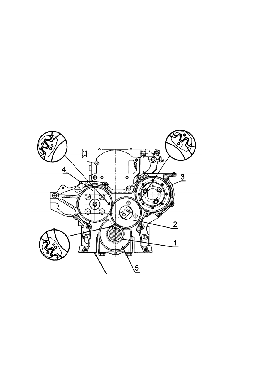
The synchronization of the crankshaft and camshaft rotation speed signals coming to an
electronic fuel supply control unit and matched with the gas distribution mechanism op-
eration is reached by installation of distribution gears according to the marks shown on
Fig.2.
1-crankshaft gear; 2 - intermediate gear; 3- fuel injection pump drive gear; 4 – camshaft gear; 5- oil
pump drive gear.
Fig.2- Distribution gears mounting diagram
1.2.2.5 Lubrication system
The diesel engine lubrication system, as shown on Fig.3, is a combined one: some parts
are lubricated under pressure, other by spraying.