Kawasaki Diesel MULE 4010 TRANS 4x4 (KAF950G9). Manual - part 108
 

  Index      Engines     Kawasaki Diesel MULE 4010 TRANS 4x4 (KAF950G9) - service manual


Search            


Content   ..  106  107  108  109   ..


Kawasaki Diesel MULE 4010 TRANS 4x4 (KAF950G9). Manual - part 108


16-14 FRAME

Seats and Seat Belts

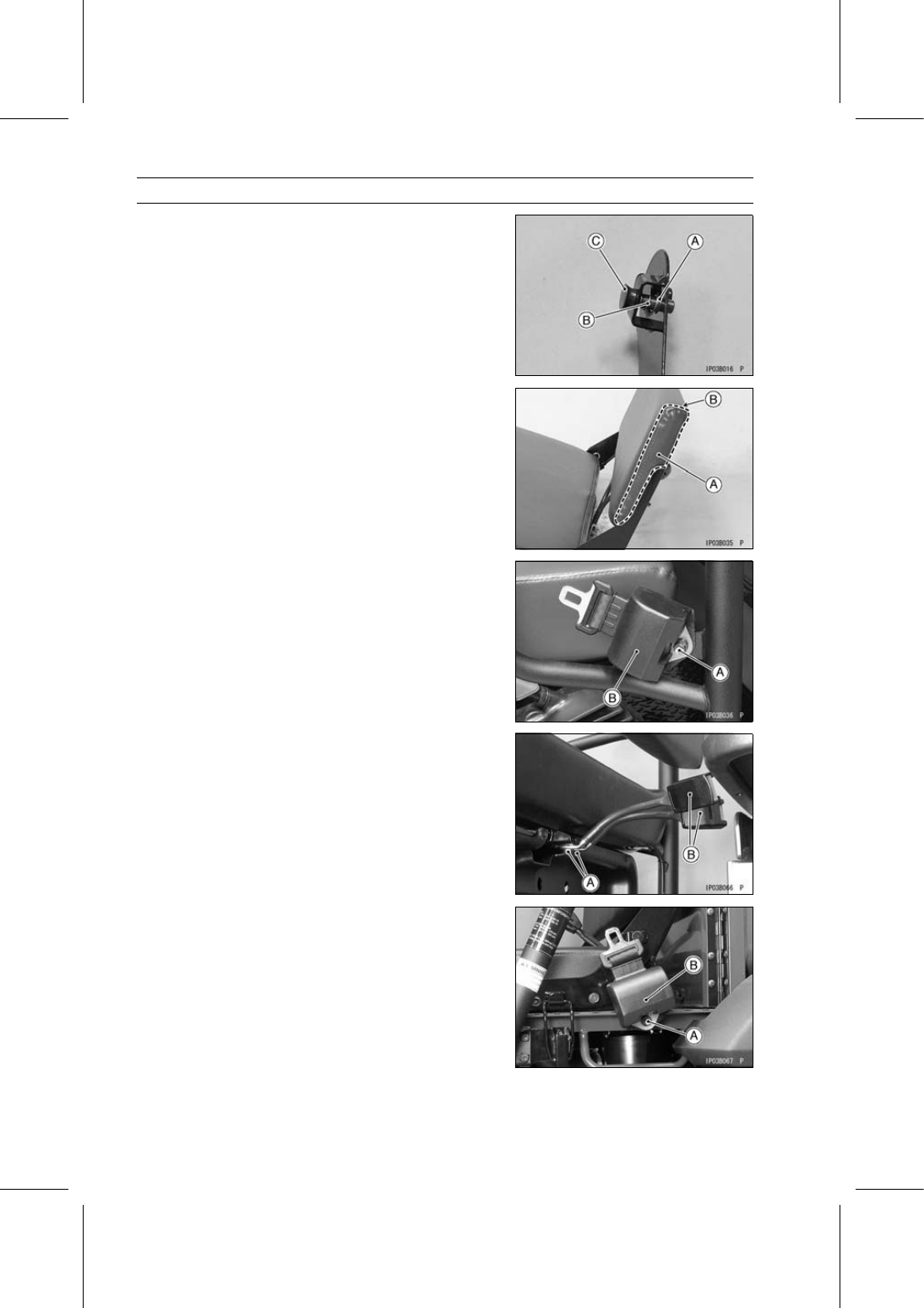
Remove (Left Side only):

Circlip [A]
Spring [B] and Pin [C]

Separate the upper lever from the bottom lever.

Rear Seat Installation

Installation is the reverse of removal, note the following.

Replace the removed nuts with new ones.

Install the rear seat back [A] so that its thicker side [B]
faces upward.

Seat Belt Removal

Remove:

Front Seat Belt Mounting Bolts [A]
Front Seat Belts [B]

Remove:

Front Seat Belt Buckle Mounting Bolts [A]
Front Seat Belt Buckles [B]

Remove:

Rear Seat Belt Mounting Bolts [A]
Rear Seat Belts [B]

FRAME 16-15

Seats and Seat Belts

Remove:

Rear Seat Belt Buckle Mounting Bolts [A]
Rear Seat Belt Buckles [B]

Seat Belt Installation

Tighten:

Torque - Seat Belt Mounting Bolts: 34 N·m (3.5 kgf·m, 25

ft·lb)

Install the front [A] and rear seat belts so that their instal-
lation angle is 40

∼ 60° [B].

Tighten:

Torque - Seat Belt Buckle Mounting Bolts: 34 N·m (3.5

kgf·m, 25 ft·lb)

Install the front seat belt buckles [A] so that their red but-
tons [B] face inside.

16-16 FRAME

Control Panel

Control Panel Removal

Remove:

Front Cargo Compartment (see Front Cargo Compart-
ment Removal)

Remove the bands [A] and clamp [B], and free the leads.

Disconnect:

Light Switch Lead Connector [C]
Oil Pressure Warning/Glow Plug Indicator Light Lead
Connector [D]
Speedometer Illumination Light Lead Connector [E]
Coolant Temperature Warning/Parking Brake Indicator
Light Lead Connector [F]
Power Steering Warning Light Lead Connector [G]
Hour Meter Lead Connector [H]
Main Switch Lead Connector [I]
Power Outlet Connector Lead Connector [J]
Fuel Gauge/Hour Meter Lead Connectors [K]
[L] KAF950G9

∼ GC/HA

[M] KAF950GD

Disconnect the horn switch lead connectors [A]
(KAF950GD).

Remove:

Bolts [A]
Speedometer Cable Upper End [B]
Speedometer [C] with Bracket

FRAME 16-17

Control Panel

Remove the steering wheel (see Steering Wheel and
Steering Shaft Removal in the Steering chapter).

Remove the control panel mounting screws [A] and col-
lars.

Open the glove compartment covers [A]

Remove the control panel [B]

Control Panel Installation

Installation is the reverse of removal, note the following.

Run the harness, cables and leads correctly (see Cable,
Wire, and Hose Routing section in the Appendix chapter).

Glove Compartment Removal

Remove:

Control Panel (see Control Panel Removal)
Screws [A]
Glove Compartment [B]


Content   ..  106  107  108  109   ..