Kawasaki Diesel MULE 4010 TRANS 4x4 (KAF950G9). Manual - part 109
 

  Index      Engines     Kawasaki Diesel MULE 4010 TRANS 4x4 (KAF950G9) - service manual


Search            


Content   ..  107  108  109  110   ..


Kawasaki Diesel MULE 4010 TRANS 4x4 (KAF950G9). Manual - part 109


16-18 FRAME

Front Cargo Compartment

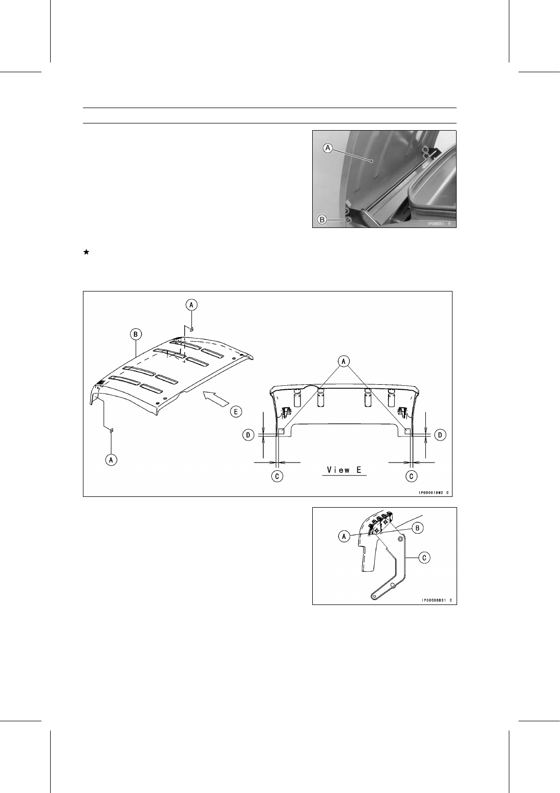
Front Cargo Hood Removal

Tilt up the cargo hood [A].

Remove:

Cargo Hood Mounting Bolts [B] and washers
Cargo Hood

Front Cargo Hood Installation

If the dampers [A] are removed from the front cargo hood
[B], install them as follows.

0

∼ 5 mm (0 ∼ 0.20 in.) [C]

2

∼ 5 mm (0.08 ∼ 0.20 in.) [D]

Installation is the reverse of removal, note the following.

Contact the bracket [A] of the front cargo hood and the
boss [B] of the arm [C].

FRAME 16-19

Front Cargo Compartment

If the hook bracket was removed from the front cargo
hood, install it as follows.

Tighten the bolts [A] while pushing the bracket [B] forward
[C].

Front Cargo Hood Cable Adjustment

Remove the front cargo compartment (see Front Cargo
Compartment Removal).

Loosen the adjuster mounting nuts [A], and slides the ad-
juster as shown in the figure.

20.5

∼ 21.5 mm (0.81 ∼ 0.85 in.) [B]

Tighten the adjuster mounting nuts securely.

Front Cargo Compartment Removal

Remove:

Front Fenders (see Front Fender Removal)
Coolant Reserve Tank (see Coolant Reserve Tank Re-
moval in the Cooling System chapter)

Remove:

Screws [A] and Collars
Tapping Screw [B] and Collar

Remove:

Side Mounting Bolts [A] (Left and Right)
Front Cargo Compartment [B]

Front Cargo Compartment Installation

Installation is the reverse of removal, note the following
parts size.

Screws [A] [L = 16 mm (0.63 in.)] and Collars [L = 4 mm
(0.16 in.)]
Screws [B] [L = 22 mm (0.87 in.)] and Collars [L = 6 mm
(0.24 in.)]
Tapping Screw [C] [L = 16 mm (0.63 in.)] and Collar [L =
4 mm (0.16 in.)]

16-20 FRAME

Cargo Bed

Cargo Bed Removal

Remove the rear fender assembly (see Rear Fender As-
sembly Removal).

Open the clamps [A] and disconnect the tail/brake light
lead connectors [B] (left and right).

Remove (Left and Right):

Bolts [C]
Tail/Brake Light Assemblies [D]

Open the steal clamp on the cargo bed and free the lead.

Unlock the hooks [A].

Raise the rear seat and push it toward the front seat back
to store.

Remove (Left and Right):

Snap Pins [A]
Cargo Bed Mounting Pins [B]

Remove the cargo bed.

Cargo Bed Installation

Installation is the reverse of removal, note the following.

Apply lithium grease (NLGI Grade No.2) to the cargo bed
mounting pins.

Check that the following are in place on the cargo bed and
frame.

Cargo Bed Rubber Dampers [A]
Frame Rubber Dampers [B]
Tail Gate Pivot Rubber Dampers (Left and Right)

FRAME 16-21

Cargo Bed

When the cargo bed is disassembled, note the following
when installing the plates and tail gate.

Be sure the clearance [A] between the back end of the
carrier [B] and the bottom of the tail gate [C] is more than
2 mm (0.079 in.) as shown in the figure (left and right).

Be sure the clearance [A] between the plate end [B] and
the tail gate end [C] is less than 5 mm (0.197 in.) as shown
in the figure (left and right).


Content   ..  107  108  109  110   ..