Kawasaki Diesel MULE 4010 TRANS 4x4 (KAF950G9). Manual - part 69
 

  Index      Engines     Kawasaki Diesel MULE 4010 TRANS 4x4 (KAF950G9) - service manual


Search            


Content   ..  67  68  69  70   ..


Kawasaki Diesel MULE 4010 TRANS 4x4 (KAF950G9). Manual - part 69


11-8 WHEELS/TIRES

Wheels (Rims)

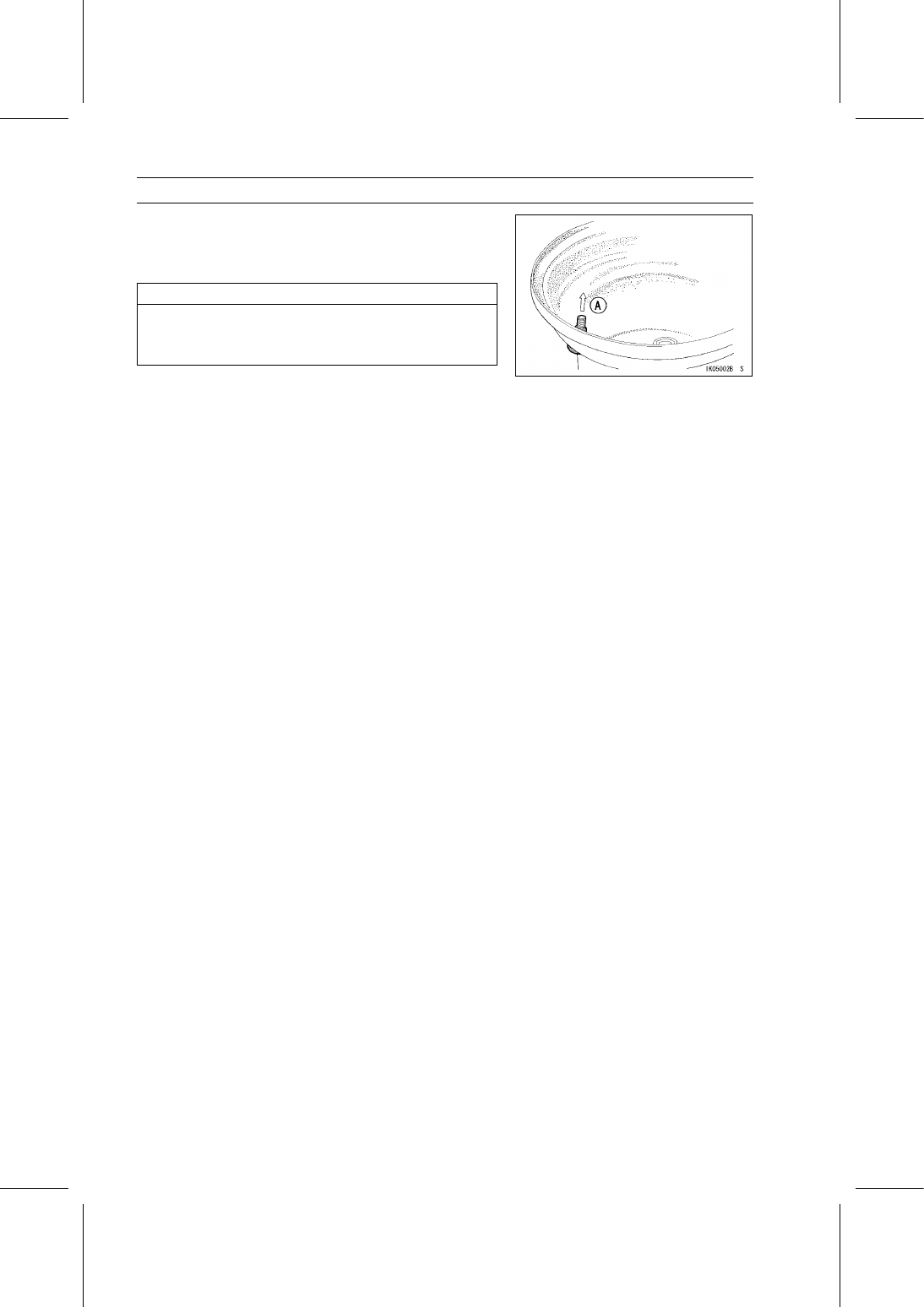
Install a new air valve in the new rim.

Remove the valve cap, lubricate the stem with a soap and
water solution, and pull [A] the stem through the rim from
the inside out until it snaps into place.

NOTICE

Do not use engine oil or petroleum distillates to lu-
bricate the stem because they will deteriorate the
rubber.

Mount the tire on the new rim.

Install the wheel (see Wheel Installation).

WHEELS/TIRES 11-9

Tires

Tire Removal

Remove:

Wheel (see Wheel Removal)
Valve Core (Let out the air)

Lubricate the tire beads and rim flanges on both sides of
the wheel with a soap and water solution, or water [A].
This helps the tire beads slip off the rim flanges.

NOTICE

Do not lubricate the tire beads and rim flanges with
engine oil or petroleum distillates because they will
deteriorate the tire.

Remove the tire from the rim using a suitable commer-
cially available tire changer.

NOTE

The tires cannot be removed with hand tools because
they fit the rims tightly.

Tire Installation

Inspect the rim.

Check the tire for wear and damage.

Replace the air valve with a new one.

NOTICE

Replace the air valve whenever the tire is replaced.
Do not reuse the air valve.

Lubricate the tire beads and rim flanges with a soap and
water solution, or water.

WARNING

Do not use any lubricant other than a water and
soap solution, or water to lubricate the tire beads
and rim because it may cause tire separation, and
a hazardous condition may result.

Install the tire on the rim using a suitable commercially
available tire changer.

Lubricate the tire beads again and center the tire on the
rim.

Support the wheel rim [A] on a suitable stand [B] to pre-
vent the tire from slipping off.

Inflate the tire until the tire beads seat on the rim.

Maximum Tire Air Pressure (to seat beads, when cold)

Front and Rear:

250 kPa (2.5 kgf/cm², 36 psi)

WARNING

Overinflating a tire can cause it to explode, causing
serious injury or death. Be sure to install the valve
core whenever inflating the tire, and do not inflate
the tire to more than maximum pressure.

11-10 WHEELS/TIRES

Tires

Check to see that the rim lines [A] on both sides of the tire
are parallel with the rim flanges [B].
If the rim lines and the rim flanges are not parallel, deflate
the tire, lubricate the sealing surfaces again, and reinflate
the tire.

After the beads are properly seated, check for air leaks.

Apply a soap and water solution around the tire bead and
check for bubbles.

Check the tire pressure using an air pressure gauge.

Tire Air Pressure (when Cold)

Front:

97 kPa (1.0 kgf/cm², 14 psi)

Rear:

167 kPa (1.7 kgf/cm², 24 psi)

Install the wheel (see Wheel Installation).

Wipe off the soap and water solution, or water on the tire,
and dry the tire before operation.

WARNING

Water or soap solution on the tire bead can cause
tire separation and an accident resulting in serious
injury or death. Do not operate the vehicle until any
water or soap solution applied to the bead has com-
pletely dried.

Tire Inspection

Refer to the Tire Wear Inspection in the Periodic Mainte-
nance chapter.

FINAL DRIVE 12-1

12

Final Drive

Table of Contents

Exploded View...................................

12-2

Specifications ....................................

12-6

Special Tools .....................................

12-7

Front Final Gear Case .......................

12-8

Front Final Gear Case Oil Level

Inspection..................................

12-8

Front Final Gear Case Oil

Change......................................

12-8

Front Final Gear Case Removal ..

12-9

Front Final Gear Case Installation

12-9

Front Final Gear Case

Disassembly..............................

12-10

Front Final Gear Case Assembly.

12-10

Differential Unit and Ring Gear

Disassembly..............................

12-11

Differential Unit and Ring Gear

Assembly...................................

12-11

LSD Clutch Torque Inspection .....

12-12

LSD Clutch Plate Inspection ........

12-13

Pinion Gear Unit Disassembly .....

12-13

Pinion Gear Unit Assembly ..........

12-13

Front Final Bevel Gear

Adjustment ................................

12-14

Backlash Adjustment ...................

12-17

Tooth Contact Adjustment............

12-18

Bevel Gear Inspection..................

12-21

Differential Gear Inspection .........

12-21

Tapered Roller Bearing

Inspection..................................

12-21

Ball Bearing Inspection ................

12-21

Oil Seal Inspection .......................

12-21

Bevel Gear Case ...............................

12-22

Bevel Gear Case Removal ..........

12-22

Bevel Gear Case Installation .......

12-22

Bevel Gear Case Disassembly ....

12-22

Bevel Gear Case Assembly .........

12-23

Drive Bevel Gear Removal ..........

12-24

Drive Bevel Gear Installation .......

12-24

Bevel Gear Adjustment ................

12-25

Backlash Adjustment ...................

12-25

Tooth Contact Adjustment............

12-27

Bevel Gear Inspection..................

12-29

Ball Bearing Inspection ................

12-29

Oil Seal Inspection .......................

12-29

Damper Inspection.......................

12-29

Propeller Shafts .................................

12-30

Propeller Shaft Removal ..............

12-30

Propeller Shaft Installation ...........

12-31

Propeller Shaft Bearing Housing

Removal ....................................

12-32

Propeller Shaft Bearing Housing

Installation .................................

12-33

Propeller Shaft Inspection............

12-33

Drive Shaft and Axles ........................

12-34

Front Axle Removal .....................

12-34

Front Axle Installation ..................

12-34

Rear Drive Shaft and Axle

Removal ....................................

12-34

Rear Drive Shaft and Axle

Installation .................................

12-35

Drive Shaft and Axle Inspection...

12-35

Dust Boot Inspection....................

12-36

Front Axle Joint Boot

Replacement .............................

12-36

Ball Bearing Inspection ................

12-42

Grease Seal Inspection................

12-43


Content   ..  67  68  69  70   ..