Tsunami2 Digital Sound Decoder. Diesel Manual - part 17
 

  Index      Engines     Tsunami2 Digital Sound Decoder. Diesel Manual 2017 year


Search            


Content   ..  15  16  17  18   ..


Tsunami2 Digital Sound Decoder. Diesel Manual - part 17


Advanced Programming 


Tsunami2 Diesel User’s Guide 


68 

Consist Example 

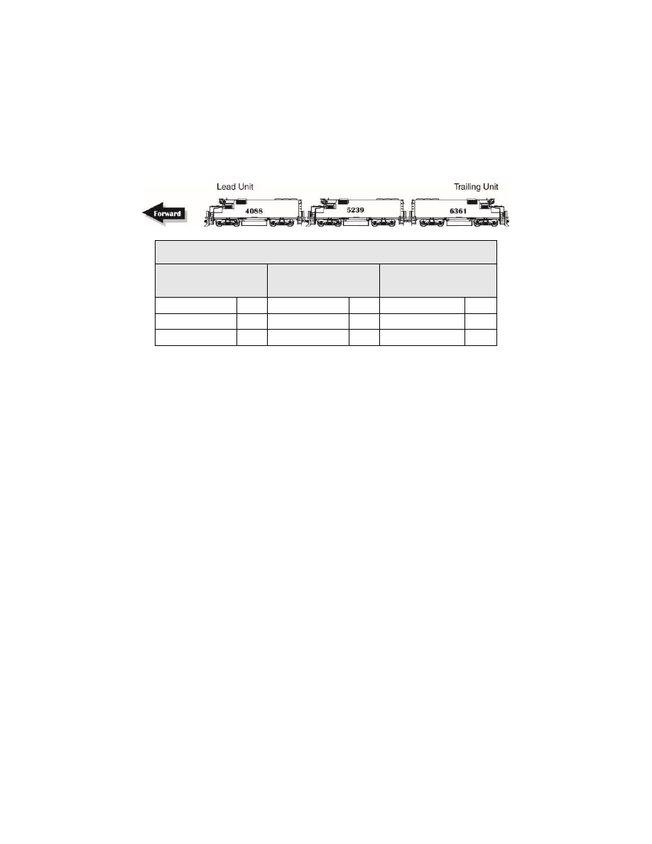
Consider a common diesel lash-up consisting of three engines: Nos. 4088, 5239, and 6361. 
Suppose you want to operate these three engines as a single unit with consist address 40. 
We’re going to enable the dynamic brake (F4 by default) and mute (F8 by default) functions for 
all engines, the headlight (F0(f) by default), airhorn (F2 by default), short airhorn (F3 by default) 
and bell (F1 by default) for the lead unit, and the backup light (F0(r) by default) for the trailing 
unit. 


Table T. Consist Example 

No.4088 

Direction: Normal 

No.5239 

Direction: Normal 

No.6361 

Direction: Inverted 

CV 19 Value 

40 

CV 19 Value 

40 

CV 19 Value 

168 

CV 21 Value 

143  CV 21 Value 

136 

CV 21 Value 

136 

CV 22 Value 

CV 22 Value 

CV 22 Value 


Lead Engine No.4088: 

1.  Program CV 19 with a value of 40 to set the consist address. 

2.  Determine the values for CVs 21 and 22. Remember, we want to enable the bell, airhorn, 

short airhorn, dynamic brake, and mute functions with CV 21, and the headlight function with 
CV 22.  

3.  To enable F1, F2, F3, F4, and F8, add the corresponding CV 21 bits together: 1 + 2 + 4 + 8 

+ 128 = 143. Set CV 21 to a value of 143 to enable the bell, airhorn, short airhorn, dynamic 
brake, and mute functions. 

4.  To enable the headlight (F0(f) by default), set CV 22 to a value of 1. 
 

Engine No.5239: 

1.  Program CV 19 with a value of 40 to set the consist address for the middle engine. 

2.  Determine the CV values for CV 21. Remember, we want to enable the dynamic brake and 

mute functions. 

3.  To enable F4 and F8, add the corresponding CV 21 bits together: 8 + 128 = 136. Set CV 21 

to a value of 136 to enable the dynamic brake and mute functions. 


Trailing Engine No.6361: 

1.  Because the trailing engine is in reverse, we need to set CV 19 to a new consist address to 

invert direction: 40 + 128 = 168.  

2.  Determine the CV values for CV 21 and 22. Remember, we want to enable the dynamic 

brake and mute functions with CV 21, and the backup light with CV 22. 

3.  To enable F4 and F8, add the corresponding CV 21 bits together: 8+ 128 = 136. Set CV 21 

to a value of 136 to enable the dynamic brake and mute functions. 

4.  To enable the backup light (F0(r) by default), set CV 22 to a value of 2. 


Miscellaneous Features 

Tsunami2 Diesel User’s Guide 


69 

Miscellaneous Features 

Configuring Analog Mode Operation 

 
Although Tsunami2 is designed to be operated with a 
DCC system, you can still use it with a conventional 
powerpack on a DC layout. The decoder operates 
entirely in response to track voltage when analog 
mode is enabled. Keep this in mind when configuring 
analog mode operation to take full advantage of the 
features offered by Tsunami2. 
 
Note: Analog mode is disabled by default. 
 

Enabling Analog Mode 

To enable analog mode, first enter a value of 1 into CV 12 (Alternate Power Source), then set 
bit 2 (APS) of CV 29 (Configuration Data 1) to 1. This will allow the decoder to receive an 
analog power source when a DCC signal is not available. For more information about adjusting 
the settings of CV 29, refer to “Configuring the Decoder.” 
 

Operating in Analog Mode 

When analog mode is enabled, the decoder will be inoperative until track voltage is received 
from the powerpack. Increasing the throttle setting to roughly 6 Volts will deliver enough voltage 
to power the decoder’s internal circuitry and activate automatic sound effects while the 
locomotive is stopped. Increasing the throttle setting to roughly 8 Volts will set the locomotion in 
motion. You may use the throttle to control locomotive speed from this point. Keep in mind that 
you can only change direction when the locomotive is stopped. To improve low-voltage 
operation, the decoder automatically adjusts motor processes and sound effect volume in 
response to back-EMF voltage measurements to compensate for changes in motor load. Refer 
to “Configuring Hyperdrive2” for more information about motor control. 
 
Note: Do not exceed the input voltage rating of the decoder as stated on the product packaging. 
This will permanently damage the decoder!  Decrease the throttle setting to zero immediately if 
this occurs. Refer to “Troubleshooting” to view each error code. 
 

Enabling Analog Mode Functions 

When operating in analog mode, the effects mapped to function keys F0-F28 will turn on 
automatically when track voltage is received, and will stay on until track voltage is removed. CV 
13 (Analog Mode Function Enable 1), CV 14 (Analog Mode Function Enable 2), CV 241 (Analog 
Mode Function Enable 3), and CV 242 (Analog Mode Function Enable 4) allow you to enable 
functions in analog mode. The decoder will automatically turn on all functions enabled for 
analog mode when track voltage is received. 
 
Note: You can enable the effects mapped to function keys in CVs 1.257-1.384 (Effect Map 
Registers) for analog mode operation with CVs 13, 14, 241, and 242. Refer to “Using Tsunami2” 
to default function assignments for F0-F2

8, and refer to “Configuring Function Mapping” to 

customize Flex-Map function mapping CVs. 
 

Follow the steps on the next page to enable functions for analog mode operation. 


Analog Mode CVs 
CV 12: Alternate Power Source 
CV 13: Analog Mode Function Enable 1 
CV 14: Analog Mode Function Enable 2 
CV 29: Configuration Data 1 
CV 218: Analog Mode Motor Start Voltage 
CV 219: Analog Mode Engine Start Voltage 
CV 241: Analog Mode Function Enable 3 
CV 242: Analog Mode Function Enable 4 
CV 243: Analog Mode Function Enable 5 

Miscellaneous Features 

Tsunami2 Diesel User’s Guide 


70 

 
Analog Mode Function Enable 1-4 

The following procedure details enabling effects mapped to F0(f), F0(r), and F1-F28 for analog 
mode operation: 

1.  Circle the CV values associated with your preferred effects mapped to function keys F0-F28. 

2.  For each CV, add the values together and record the sum in the space provided. You should 

have four total CV values for enabling your preferred function keys when finished. 

3.  Enter each value into CVs 13, 14, 241, and 242 to enable your preferred functions for 

analog mode operation. 

 
CV 13: Analog Mode Function Enable 1 


Bit 7 

Bit 6 

Bit 5 

Bit 4 

Bit 3 

Bit 2 

Bit 1 

Bit 0 

Function 

F8 

F7 

F6 

F5 

F4 

F3 

F2 

F1 

CV Value 

128 

64 

32 

16 


CV 13 Value = _____ 

 
CV 14: Analog Mode Function Enable 2 


Bit 7 

Bit 6 

Bit 5 

Bit 4 

Bit 3 

Bit 2 

Bit 1 

Bit 0 

Function 

F12 

F11 

F10 

F9 

F0(r) 

F0(f) 

CV Value 

32 

16 


CV 14 Value = _____ 

 
CV 241: Analog Mode Function Enable 3 


Bit 7 

Bit 6 

Bit 5 

Bit 4 

Bit 3 

Bit 2 

Bit 1 

Bit 0 

Function 

F20 

F19 

F18 

F17 

F16 

F15 

F14 

F13 

CV Value 

128 

64 

32 

16 


CV 241 Value = _____ 

 
CV 242: Analog Mode Function Enable 4 


Bit 7 

Bit 6 

Bit 5 

Bit 4 

Bit 3 

Bit 2 

Bit 1 

Bit 0 

Function 

F28 

F27 

F26 

F25 

F24 

F23 

F22 

F21 

CV Value 

128 

64 

32 

16 


CV 242 Value = _____ 


Miscellaneous Features 

Tsunami2 Diesel User’s Guide 


71 


Enabling Analog Mode Automatic Effects 

To provide more versatility, CV 243 (Analog Mode Function Enable 5) can be used in 
conjunction with Flex-Map function mapping CVs to allow automatic effect configuration for 
analog mode operation. Automatic effects will respond to direction and movement when 
enabled. Table U shows the CV values for configuring effects to respond according to the 
following circumstances: 

Forward-Driving: Effect is turned on when the 
locomotive is moving in the forward direction. 

Reverse-Driving: Effect is turned on when the 
locomotive is moving in the reverse direction. 

Forward-Standing: Effect is turned on when the 
locomotive is stopped in the forward direction. 

Reverse-Standing: Effect is turned on when the 
locomotive is stopped in the reverse direction. 
 
Note: CV 243 can be set to allow any 
combination of auto-effect enable. For instance, 
a value of 10 will allow the effect to turn on in the 
reverse direction regardless of movement, and a 
value of 3 will allow the effect to turn on when 
the locomotive is in motion regardless of 
direction. 
 

Set the Analog Mode Start Voltage 

CV 218 (Analog Mode Motor Start Voltage) can be used to set the track voltage level at which 
power is applied to the motor to avoid the “motor-boating” effects that sometimes occur when 
using marginal powerpacks.  
 
Entering a value of 0 into CV 218 will set the starting voltage to 6V. Entering a value of 255 into 
CV 218 will set the starting voltage to the maximum setting. Set CV 218 to the lowest value that 
still achieves desired results. The motor will not start when the Voltage level in CV 218 is set to 
an excessively high value. 
 
Note: Starting the motor at too low a voltage can cause the voltage from the powerpack to sag, 
resulting in a condition where the decoder loses power when attempting to power the motor. 
 

Starting Voltage = (CV 218 ÷ 10) + 6V 


Set the Analog Mode Engine Start Voltage 

CV 219 is used to adjust the voltage level applied to activate engine exhaust sound effects in 
analog mode. The engine exhaust start Voltage is calculated as a fraction of the minimum 
voltage required to power the decoder (6V). Starting Voltage is calculated as: 
 

Starting Voltage = (CV 219 ÷ 10) + 5V 

 
Entering a value of 0 into CV 219 will set the engine exhaust start Voltage level to 6V. Entering 
a value of 255 into CV 219 will set the engine exhaust start voltage level to the maximum setting 


Table U. CV 243 Auto-Effect Enable 

CV Value  Active When 

Never Active 

– Disabled 

Forward-Driving 

Reverse-Driving 

Driving 

Forward-Standing 

Forward 

Forward-Standing, Reverse-Driving 

Forward, Reverse-Driving 

Reverse-Standing 

Reverse-Standing, Forward-Driving 

10 

Reverse 

11 

Reverse, Forward-Driving 

12 

Standing 

13 

Standing, Forward-Driving 

14 

Standing, Reverse-Driving 

15 

Continuously Active 


Content   ..  15  16  17  18   ..