Tsunami2 Digital Sound Decoder. Diesel Manual - part 15
 

  Index      Engines     Tsunami2 Digital Sound Decoder. Diesel Manual 2017 year


Search            


Content   ..  13  14  15  16   ..


Tsunami2 Digital Sound Decoder. Diesel Manual - part 15


Advanced Programming 


Tsunami2 Diesel User’s Guide 


60 

NMRA Legacy Function Mapping 

CVs 33-46 (Function Status CVs) are function mapping CVs stated in the NMRA Standards for 
DCC Configuration Variables (S-9.2.2). CVs 35-46 are used to assign effects to function keys 
F1-F12, and CVs 33 and 34 are used to assign effects to the F0 function key. If the same effect 
is selected for both reverse and forward F0 functions, that effect will turn on when the F0 
function key is turned on regardless of locomotive direction. 
 
Note: CVs 33-46 are set to values of 0 by default, are a secondary method of function mapping, 
and are not used to determine Tsunami2’s default function assignments.  
 
CVs 1.257-1.512 (Extended Function Mapping CVs) provide default function assignments for 28 
function keys and offer comprehensive function mapping s

upport for all of Tsunami2’s effects in 

an uncomplicated and versatile format. However, mapping an effect to a function key (F0(f), 
F0(r), or F1-F12) using CVs 33-46 will override the corresponding function assignment mapped 
within CVs 1.257-1.384. As a result, the use of Legacy Function Mapping and Flex-Map 
Function Mapping together may produce undesirable results and is not recommended. 
 

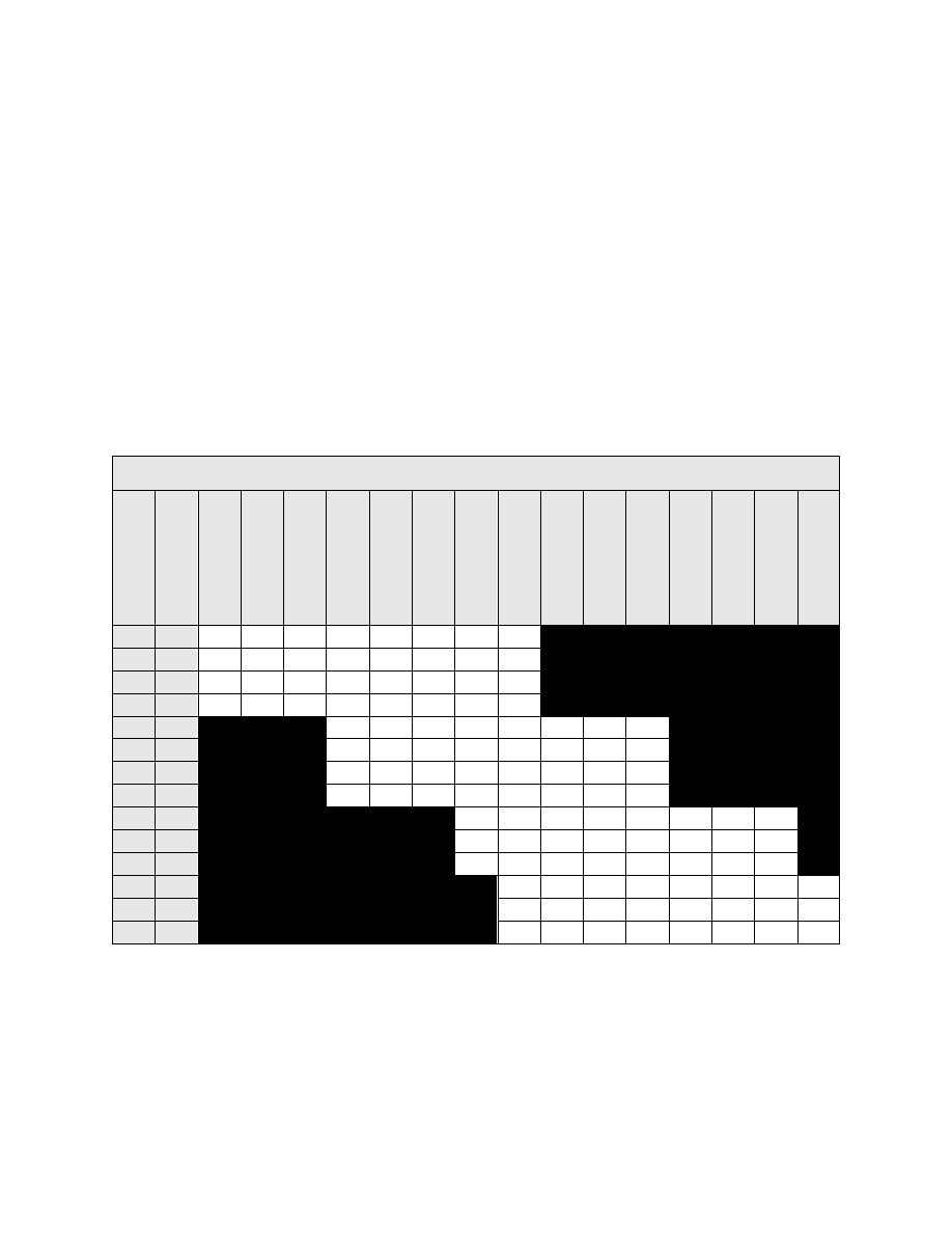
Table R. Legacy Function Output Map 

F

u

n

ctio

n

 Key


CV


HL O

utp

ut


B

L Out

pu

A

ir

h

orn


B

el

F

X

3 Out

pu

F

X

4 Out

pu

Dy

na

mi

c

 B

rak

e


S

ho

rt 

A

ir

ho

rn


S

tr

ai

gh

t-

to

-E

igh

G

en

eral

 S

erv

ic

e


Di

m

me

Mute


HE

P

 Mo

de


Ind

./Tr

a

in 

B

rak

e


Coup

ler


F0(f)  33 

16 

32 

64 

128 


F0(r)  34 

16 

32 

64 

128 

F1 

35 

16 

32 

64 

128 

F2 

36 

16 

32 

64 

128 

F3 

37 


16 

32 

64 

128 

F4 

38 

16 

32 

64 

128 

F5 

39 

16 

32 

64 

128 

F6 

40 

16 

32 

64 

128 

F7 

41 


16 

32 

64 

128 

F8 

42 

16 

32 

64 

128 

F9 

43 

16 

32 

64 

128 

F10 

44 


16 

32 

64 

128 

F11 

45 

16 

32 

64 

128 

F12 

46 

16 

32 

64 

128 


Advanced Programming 


Tsunami2 Diesel User’s Guide 


61 

Configuring Hyperdrive2 

 
Tsunami2 features Hyperdrive2 advanced motor control, 
providing high-frequency pulse-width modulation (PWM) for 
silent motor control and a back-electromotive force (back-
EMF) sensor to improve low-speed operation and maintain 
constant speeds. Load compensation and a proportional-
integral (PI) control loop allows Tsunami2 to sense motor 
load in response to back-EMF measurements. 
 

Setting Engine Recovery Speed 

Use CV 119 (Max Engine Recovery Speed) to designate the speed the motor will resume after 
momentary power losses. The recovery speed can be determined as a fixed speed step 
(absolute limiting) or a fraction of the throttle setting (proportional limiting). 
 
The locomotive speed will start at speed-
step 0 after power losses when CV 119 is 
set to a value of 0 or 128. CV 119 is set to 
a value of 204 by default. Entering a value 
from 1 to 127 will designate the recovery 
speed as a fixed speed step from 1 to 127 
(absolute limiting). If the recovery speed 
step in CV 119 is greater than the last 
speed step before power loss, the decoder 
will resume the throttle setting being 
received from the command station. 
 
Entering a value from 129 to 255 will designate the recovery speed as a fraction of the current 
throttle setting (proportional limiting). Higher values indicate higher speed settings. The decoder 
calculates the recovery speed after power losses as:  
 

Recovery Speed = (CV 119 × Speed Step) ÷ 127 


Adjusting Low-Speed Operation 

CV 211 (Low-Speed Compensation) is used to compensate for irregularities (if any) that occur 
during low-speed operation. You may enter values from 0 to 255 into CV 211 to specify the 
“gain value” that will be applied to the PID motor equation at low speeds. 
 
Increasing the gain value will allow the motor to operate smoother at lower speeds. When  
CV 211 is set to a value of 255, the effect is applied across the first nine speed steps; the gain 
value has a decreasing effect upon the motor as speed steps increase. This helps compensate 
for motors that are more difficult to start. 
 
In the event that you have an efficient motor that already spins at minimal voltages, it is possible 
that setting the gain value too high could elevate the locomotive’s minimum speed, and/or cause 
a stutter at low speeds while the control loop attempts to slow the motor. If you notice this, 
reduce the value of CV 211. We suggest setting CV 211 to the lowest value that will still improve 
low-speed operation. 


Advanced Motor Control CVs 
CV 10: EMF Feedback Cutout 
CV 119: Max Engine Recovery Speed 
CV 209: PID Kp Parameter 
CV 210: PID Ki Parameter 
CV 211: Low-Speed Compensation 
CV 212: BEMF Feedback Intensity 
CV 215: BEMF Reference Voltage 
CV 216: Motor Speed-Step Deadband 
CV 217: Motor Control Register 
CV 220: Constant Brake Distance 

CV 119: Max Engine Recovery Speed 

0 = Disabled 
1 = Speed-step 1 

↓ 

127 = Speed-step 127 (absolute limiting) 
128 = Disabled 
129 = 1% of throttle setting (proportional limiting) 


255 = 100% of throttle setting (proportional limiting) 

Advanced Programming 


Tsunami2 Diesel User’s Guide 


62 

Control Loop Coefficients 

Tsunami2 compensates for load changes in response to back-EMF voltage readings that 
compare motor load to locomotive speed. When a variation between them occurs, a 
proportional-integral (PI) control loop adjusts the motor voltage to compensate for the difference 
so that the locomotive’s speed remains consistent. Adjust the PI control loop with CV 209 (PID 
Kp Parameter) and CV 210 (PID Ki Parameter). 
 

Kp Coefficient 

CV 209 is used for adjusting the proportional gain of the control loop, and compensates for 
dynamic changes in the motor load based on the contrast between the throttle setting and motor 
speed. CV 209 may be programmed with a value from 0 to 255. Higher values indicate higher 
levels of compensation. However, values that are too high may lead to inconsistencies in motor 
control. 
 

Ki Coefficient 

CV 210 is used for adjusting the integral gain of the control loop, and compensates for static 
changes in motor load by applying a correction based on the integral difference between the 
throttle setting and the current motor speed. CV 210 may be set to a value from 0 to 255. Higher 
values indicate higher levels of compensation and a more sensitive control loop. We suggest 
setting CV 210 to the lowest value that still provides optimal performance; setting CV 210 to 
values that are too high may lead to oscillations in locomotive speed. 
 
Note: Setting CVs 209 and 210 to values of 0 will disable the control loop and is not 
recommended. 
 

Strategy for Optimizing Hyperdrive2 

Finding the right combination of CV settings requires some experimenting and patience. Be 
aware that these settings will inherently vary between locomotives. If you happen to make an 
adjustment to an advanced motor control CV that compromises operation in some way, you can 
reset CV settings with CV 8 (Manufacturer ID). Refer to 

“Introduction to Programming” for more 

information. 
 
Use your CV settings as starting points when configuring other locomotives. Adjusting a 
particular setting can actually degrade performance, and therefore changes should be made in 
small increments until you find your preferred 

result. And remember, the decoder’s default 

settings should provide satisfactory performance for most situations. 
 

Example: Adjusting the Control Loop 

We suggest the following procedure to help fine-tune the CV settings: 

1.  Make sure all the Hyperdrive2 CVs are set to default values. 

2.  Set CV 2 (Vstart), CV 5 (Vhigh), and CV 6 (Vmid) to 0. 

3.  With the locomotive on level track, set the throttle to speed-step 20. 

4. 

Increase the value of CV 209 until the locomotive’s speed becomes varied and choppy. 

5.  Reduce the value of CV 209 until speed is consistent, smooth, and without variance. 

6.  Increase the value of CV 

210 until you notice the locomotive’s speed begin to oscillate. 

7.  Reduce the value of CV 210 until the oscillation stops. 


Advanced Programming 


Tsunami2 Diesel User’s Guide 


63 

Setting the Load Compensation Curve 

CV 10 (EMF Feedback Cutout) and CV 212 (Back-EMF Feedback Intensity) are used to control 
the amount of load compensation applied to the motor across the throttle range. CV 212 can be 
set to a value from 0 to 255 to determine the amount of load compensation that is initially 
applied to the motor. A value of 0 disables load compensation altogether, while a value of 255 
corresponds to 100% compensation. CV 10 determines the degree that the load compensation 
is reduced as the throttle speed is increased. 
 
When CV 10 is set to 0, the amount of load compensation is constant over the entire speed 
range, according to the value of CV 212. Setting CV 10 between 1 and 127 will determine the 
speed step at which the load compensation is reduced to 0. Setting CV 10 between 128 and 
255 will select a partial load compensation reduction at full speed. The minimum load 
compensation level at speed-step 128 is calculated and illustrated as follows: 
 

BEMF Intensity = CV 212 x (1 

– (speed step ÷ CV 10)) ÷ 255 

 
In general, you will want to have full load compensation at low speeds that will gradually reduce 
to 0 at top speed. Set CV 10 to 126 to achieve this. When operating in a consist, you may need 
to reduce the value in CV 212 to reduce the low speed load compensation, and therefore avoid 
pitting the locomotives against each other. 
 

BEMF Reference Voltage 

CV 215 (BEMF Reference Voltage) allows you to change the reference voltage for the  
back-EMF to match the voltage on your track. By matching the back-EMF reference voltage of 
the decoder with your track voltage, your locomotive will run smoother and more consistently. 
CV 215 may be programmed with any value from 60 to 255 to set the back-EMF reference 
Voltage from 6 to 25.5 volts. 
 
If you are planning to consist the model with other models equipped with SoundTraxx decoders 
(such as Tsunami or MC1 and MC2 DCC Mobile Decoders), make sure that the value entered 
in CV215 is equal to the observed voltage of the track output from your command station, so 
that the reference voltage is identical to your other decoders. To set this CV, simply take the 
observed voltage on your track and multiply it by 10 to calculate the programming value. For 
example, 12.5 Volts would be represented as a CV value of 125.


Setting the Motor Speed-Step Deadband 

CV 216 (Motor Speed-Step Deadband) determines the speed step at which voltage is first 
applied to the motor to set the locomotive in motion. Entering values from 1 to 126 into CV 216 
will set the motor speed-step Deadband from speed-step 1 to speed-step 126. Setting CV 216 
to higher values will allow the locomotive to remain stationary as the throttle is increased from 
zero.  


Content   ..  13  14  15  16   ..