Tsunami2 Digital Sound Decoder. Diesel Manual - part 12
 

  Index      Engines     Tsunami2 Digital Sound Decoder. Diesel Manual 2017 year


Search            


Content   ..  10  11  12  13   ..


Tsunami2 Digital Sound Decoder. Diesel Manual - part 12


Advanced Programming 


Tsunami2 Diesel User’s Guide 


48 


Table L. CV 225: EQ Control Register 

*Cut/boost values for CVs 226-232 shown in red 

CV Value   Description 

62Hz 

CV 226 

125Hz 

CV 227


250Hz 

CV 228


500Hz 

CV 229


1kHz 

CV 230


2kHz 

CV 231


4kHz 

CV 232


Flat 

0dB 

128 

0dB 

128 

0dB 

128


0dB 

128


0dB 

128


0dB 

128


0dB 

128


Micro Speaker 
(smaller than 1”) 

-12dB 

0


-12dB 

0


+7.12dB 

200 

+3dB 

160


+1.5dB 

140


+0.8dB 

132 

0dB 

128


Small Speaker 
(1” to 2”) 

-6dB 

60 

-3dB 

96


+4.1dB 

168


+3dB 

160


0dB 

128


0dB 

128


+0.8dB 

132


Medium Speaker 
(2” to 4”) 

-3dB 

96 

+4.1dB 

168 

+2.3dB 

148 

+1.1dB 

136 

0dB 

128


0dB 

128


0dB 

128


Large Speaker 
(larger than 4”) 

+6dB 

192 

+3dB 

160 

+1.5dB 

140 

0dB 

128


0dB 

128


0dB 

128


0dB 

128


Custom EQ Levels 

+/-12dB 

0-255


+/-12dB 

0-255


+/-12dB 

0-255


+/-12dB 

0-255


+/-12dB 

0-255


+/-12dB 

0-255


+/-12dB 

0-255


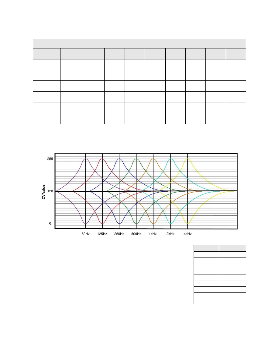
The graph below indicates the minimum-to-maximum frequency response for each band. Notice 
the overlap from one frequency band to the next. Keep in mind that adjusting the response with 
one CV will raise or lower the sounds of nearby frequencies as well. 


Making adjustments while sounds are playing is the easiest way to set 
the EQ because you can listen to each response. Because of this, we 
recommend programming this feature on the mainline in Operations 
Mode

. Start with CV 226 and make adjustments until you’re satisfied 

with each band’s frequency response. Depending upon the speaker 
you’re using, adjusting the lowest frequency bands may have little or 
no effect. If this is the case, the audio frequencies are out of the 
speaker’s range, and we suggest that you set the CV to 0 (-12dB). 
 
Note: Setting the cut/boost levels in CVs 226-232 to values that are 
too high may result in poor sound responses or damage the speaker. 
Ensure that equalizer settings do not exce

ed your speaker’s power rating to avoid this. 

CV Value  Cut/Boost 

255 

+12dB 

224 

+9dB 

192 

+6dB 

160 

+3dB 

128 

0dB 

96 

-3dB 

64 

-6dB 

42 

-9dB 

-12dB 

Advanced Programming 


Tsunami2 Diesel User’s Guide 


49 

Setting Reverb 

The reverb effect allows you to add a bit of ‘presence’ to sound effects. CV 233 (Reverb Control 
Register) allows you to choose between preset reverb options for sound effects or select user-
adjustable reverb. CV 234 (Reverb Output Level), CV 235 (Reverb Delay Time), and CV 236 
(Reverb Feedback Gain Level) are used to set up reverb for the sound effects assigned to CVs 
161-192 (Reverb Mixer). 
 
Note: Making big adjustments within reverb control CVs can easily result in unpleasant results. 
We recommend you take your time and experiment with small changes first when configuring 
this feature. 
 

Reverb Control Register 

CV 233 allows you to select reverb presets or user-
adjustable reverb. Setting CV 233 to reverb presets 
will automatically adjust CVs 234-236. 
 
User-adjustable reverb works by simulating the effect 
created when a sound wave is heard with a delayed 
version of the sound that has been reflected off 
another hard surface. The decoder’s reverb is 
designed to produce an effect due to early sound 
reflections off a nearby surface such as a rock cut or 
canyon wall. User-adjustable reverb provides three 
controls plus a reverb mixer. 
 

Reverb Output Level 

CV 234 determines the amount of reverb signal that is mixed back with the original audio signal, 
and may be set to a value from 0 (minimum) to 255 (maximum). 
 

Reverb Delay Time 

CV 235 determines the overall reverb delay time from 0 to 255 milliseconds. CV 235 may be set 
to a value from 0 (zero delay) to 255 (maximum delay). The reverb delay time is calculated as: 
 

Delay Time = CV 235 × 1ms 

 
Longer delay times correspond to a greater distances between the sound source and the 
reflecting surfaces and will generally result in increased reverb. 
 

Reverb Feedback Level 

CV 236 specifies the percentage of the r

everb’s output that is mixed back into the input and 

creates the effect of multiple sound reflections, each diminishing in amplitude over time. CV 236 
may be set to a value from 0 to 255 to adjust the amount of feedback from 0% to 100%. 
 
Note: High feedback settings (greater than a value of 200) should be avoided, as they can 
result in strange sounding effects. Adjust this CV starting with a low initial value and increase in 
small steps.


Reverb Mixer 

Adjusting CVs 161-192 allows you to apply the reverb effect to desired sound effects. There are 
reverb inputs for each sound effect that control the percentage of the original audio level that will 
be mixed into the reverb. Each send level may be set from 0 to 255 to adjust the percentage 
from 0% to 100%. CVs 161-192 are listed on the following page. 

CV 233: Reverb Control Register 

CV Value 

Reverb Preset 

Disabled 

Short Reverb (default) 

Medium Reverb 

Long Reverb 

Short Echo 

Long Echo 

Extra Long Echo 

User-Adjustable 

Advanced Programming 


Tsunami2 Diesel User’s Guide 


50 

CVs 161-192: Reverb Mixer 

CV 

Sound Effect 

Default Value 

161 

Airhorn 

128

#


162 

Bell 

163 

Prime Mover 

164 

Air Compressor 

165 

Dynamic Brake 

166 

Radiator Fans 

167 

Alarm Bell 

168* 

Gas Turbine* 

169 

Coupler 

170 

Train Brake Apply/Release 

171 

Independent Brake Apply 

172 

Independent Brake Release 

173* 

GenSet Prime Mover 2

*


174* 

GenSet Prime Mover 3* 

175 

Poppet Valve 

128

#


176 

Steam Generator or Auxiliary HEP Generator

^


177 

Cab Doors 

178 

Reserved 

179 

Relay Clicks 

180 

E-Brake App. 

181 

Glad Hand Release 

182 

All Aboard/Coach Doors 

183 

Reserved 

184 

Reserved 

185 

Clickety-Clack 

186 

Sander Valve 

187 

Fuel Loading 

188 

Air Conditioner 

189 

Wrenches 

190 

Pneumatic Oilers 

191 

Toilet Flush 

192 

Cab Chatter 


#

 Default values for these CVs will vary by software release. 


*

 Not included in software releases prior to version 1.2. 


^

 The steam generator effect is included with all software revisions but the auxiliary HEP generator effect 

is not included in software releases prior to version 1.2. 

Advanced Programming 


Tsunami2 Diesel User’s Guide 


51 

How to Adjust Reverb Control CVs 


Setting up the reverb involves a bit of trial and error and is best done while the sounds are 
playing, using Operations Mode programming to make the adjustments. Start by setting CV 233 
to 7 to enable the user-adjustable reverb. Next, set CVs 234-236 to a nominal value. We like to 
start with the settings of 64 for CV 234, 255 for CV 235, and 64 for CV 236. Then determine the 
sounds you wish to apply reverb to and try setting the corresponding reverb mixer CV (CV 161-
192) to a value between 96 and 192. If you are using multiple reverb inputs, each can be set to 
a different value so that more or less reverb is added to a particular sound effect as desired. 
With the recommended reverb control settings, you should notice a definite amount of reverb 
added to the sound and can begin making further adjustments. 
 
Like any sound effect, it is possible to over-adjust a particular setting within the reverb control 
CVs and create an artificial sounding effect. Make adjustments in small steps and let your ears 
be the judge! 


Content   ..  10  11  12  13   ..