Tsunami2 Digital Sound Decoder. Diesel Manual - part 7
 

  Index      Engines     Tsunami2 Digital Sound Decoder. Diesel Manual 2017 year


Search            


Content   ..  5  6  7  8   ..


Tsunami2 Digital Sound Decoder. Diesel Manual - part 7


Basic Programming 


Tsunami2 Diesel User’s Guide 


28 

Configuring Lighting Outputs 

 
Tsunami2 provides up to six lighting outputs (depending on 
the board format). Lighting output control CVs allow you to 
enable Hyperlight effects, Grade-Crossing Logic, phase offset, 
and LED Compensation Mode for each lighting output, 
determine lighting output direction, adjust the flash rate of 
flashing Hyperlight effects, and set lighting output brightness 
levels. 
 

Enabling Hyperlight Effects and Features 

You can use CVs 49-54 to enable Hyperlight lighting effects 
and features for the headlight, backup light, and FX3-FX6 
lighting outputs. This section details each Hyperlight effect 
and feature and shows you how to customize lighting outputs 
to fit your operating preferences. 
 

On/Off Output 

The on/off lighting effect provides on/off control for 
the corresponding function. Use this effect when 
the function output is being utilized to drive 
external electronics such as a low power relay to 
control a smoke generator or a servo motor. 
 

Dimmable On/Off Headlight 

The output set to the dimmable headlight will be 
reduced to the brightness setting in CV 63 when 
you turn on the dimmer function (F7 by default). 
 

Mars Light 

The Mars light warning beacon follows the famous 
figure-eight sweep pattern and oscillates more 
rapidly than the Gyralite. 
 

Pyle-National Gyralite 

The Pyle-National Gyralite is similar to the Mars 
Light, but oscillates in a circular or elliptical pattern. 
 

Oscillating Headlight 

The dual-oscillating headlight generates two 
beams that follow each other in a tight, circular 
sweep pattern. 
 

Single-Flash Strobes 1 and 2 

The xenon single-flash strobe 1 effect flashes once 
during each flash rate timing cycle. The xenon 
single-flash strobe 2 flashes once during each flash 
rate timing cycle, but at a slightly faster rate.  
 
This effect allows you to mimic warning lights found 
on many Amtrak locomotives as well as remote control operated (or “RCO”) locomotives. 
 

Lighting Output Control CVs 
CV 49: Headlight Configuration 
CV 50: Backup Light Configuration 
CV 51: FX3 Configuration 
CV 52: FX4 Configuration 
CV 53: FX5 Configuration* 
CV 54: FX6 Configuration* 
CV 57: Forward Direction Enable 
CV 58: Reverse Direction Enable 
CV 59: Hyperlight Flash Rate 
CV 60: Grade-Crossing Hold Time 
CV 61: Brightness Register 1 
CV 62: Brightness Register 2 
CV 63: Dimmer Level 
CV 64: Master Brightness Level 
*Available on select formats 

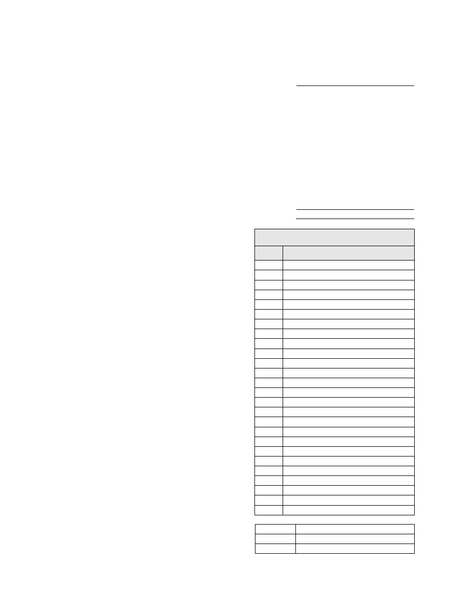
Table E. Hyperlight Effect Select 

Value  Lighting Effect 

On/Off Output 

Dimmable On/Off Headlight 

Mars Light 

Pyle-National Gyralite 

Oscillating Headlight 

Single-Flash Strobe 1 

Double-Flash Strobe 

Western-Cullen D312 Rotary Beacon 

Prime Stratolite 

Ditch Light Type I 

10 

Ditch Light Type II 

11 

Flashing Rear End Device (FRED) 

12 

Engine Exhaust Flicker (Diesel) 

13 

Firebox Flicker (Steam) 

14 

Smart Firebox Flicker (Steam) 

15 

Dyno-Light 

16 

Auto-Dim Forward 

17 

Auto-Dim Reverse 

18 

Brake Light 

19 

On/Off 

– Brightness 1 

20 

On/Off 

– Brightness 2 

21 

Emergency Gyralite 

22 

Reserved 

23 

Ash Pan Flicker (Steam) 

24 

Reserved 

25 

Single-Flash Strobe 2 

+32 

Phase Offset (Phase B) 

+64 

Grade-Crossing Logic 

+128 

LED Compensation Mode 

Basic Programming 


Tsunami2 Diesel User’s Guide 


29 

Double-Flash Strobe 

The xenon double-flash strobe effect emits two rapid flashes of light during each flash rate 
timing cycle. CV 59 is used to modify the flash rate timing cycle. 
 

Western-Cullen D312 Rotary Beacon 

The Western-Cullen D312 Rotary Beacon effect follows a revolving reflector and bulb assembly 
flash-pattern. 
 

Prime Stratolite 

The Stratolite is made up of four individual lamps arranged in a circular pattern. The Stratolite 
flashes in a clockwise direction in a mechanical “stepped” fashion, unlike the smooth motion of 
the rotary beacon. 
 

Ditch Lights Type I and II 

Ditch lights type I and II flash together by default. When Grade-Crossing Logic is enabled, ditch 
light I assumes 

a steady “on” state before and after the crossing hold timer countdown. 

Conversely, ditch light II will remain off before and after the crossing hold timer countdown. To 
configure alternating ditch lights, set one lighting output to ditch light I or II and enable Grade-
Crossing Logic, and then set a second lighting output to the same ditch light and enable Grade-
Crossing Logic and phase offset. 
 

Flashing Rear End Device (FRED) 

The FRED effect is a flashing red taillight that indicates the rear of the train. 
 

Engine Exhaust Flicker 

This effect produces a random flicker whose intensity increases with locomotive speed. This 
effect is best used by placing a red/orange LED in the exhaust stack. As the locomotive 
increases speed, it will glow brighter, imitating an increase in sparks and exhaust gases. 
 

Dyno-Light 

In a diesel locomotive, the lights will fade on and fade off to simulate the heating and cooling of 
the bulb filaments. 
 

Auto-Dim Forward and Reverse 

The auto-dim forward effect will automatically dim lighting outputs to the dimmer level in CV 63 
when in the forward direction, and the auto-dim reverse effect will automatically dim lighting 
outputs to the dimmer level in CV 63 when in the reverse direction. 
 

Brake Light 

The brake light effect is dimmed to the brightness setting in CV 63 when active. The brake light 
brightness level will be automatically set to 100% when you turn on the independent or train 
brake function (F11 by default). 
 

On/Off Brightness 1 and 2 

On/Off Brightness effects 1 and 2 allow you to independently adjust the level of up to 2 lighting 
outputs. You can accurately recreate low brilliance lighting effects on your model such as class 
lights, lit number boards or marker lamps. The on/off brightness 1 and 2 effects will set lighting 
outputs to the brightness levels of CVs 61 and 62, respectively.  
 

Emergency Gyralite 

The emergency Gyralite follows the same oscillating sweep pattern as the Gyralite, and will 
automatically disable all active lighting effects. 

Basic Programming 


Tsunami2 Diesel User’s Guide 


30 

Phase Offset 

Add a value of 32 to the value of flashing Hyperlight effects to set the corresponding lighting 
output to Phase B from Phase A. Flashing effects set to Phase B will flash opposite of flashing 
effects set to Phase A, i.e., Phase A turns off when Phase B turns on, and Phase A turns on 
when Phase B turns off. 
 

Grade-Crossing Logic 

Grade-Crossing Logic allows you to set up lighting functions, the bell, and airhorn to 
automatically simulate encountering grade crossings. Add a value of 64 to enable Grade-
Crossing Logic. Turning on the long airhorn function (F2 by default) or the grade-crossing signal 
function (F9 by default) will start the crossing hold timer countdown and allow lighting effects to 
assume a flashing state. Shown in Table F, flashing Hyperlight effects will return to an on or off 
state after the countdown ends. Practice activating Grade-Crossing Logic as your locomotive 
approaches a grade crossing. You can adjust the crossing hold timer countdown from 0 to 15 
seconds by entering a value from 0 to 15 into CV 60 (Grade-Crossing Hold Time). 
 
To allow the bell to ring during the crossing hold timer countdown, enable the grade-crossing 
bell feature in CV 122 (Bell Select)

. Refer to “Configuring Sound Effects” for more information 

about the grade-crossing bell. 
 
Refer to Table F located below for a list of Hyperlight effects commonly configured with Grade 
Crossing Logic (including alternating ditch lights) and corresponding CV values. The state of the 
effect while the Grade Crossing Logic hold timer is not active is also listed.    
 

Table F. Commonly Configured Hyperlight Effects  

Effect Type 

CV Value 

Grade Crossing 

Logic Effect State 

Crossing Logic Off  Crossing Logic On 

Phase A  Phase B   Phase A  Phase B 

Mars Light 

34 

66 

98 

On 

Pyle-National Gyralite 

35 

67 

99 

On 

Oscillating Headlight 

36 

68 

100 

On 

Single-Flash Strobe 1 

37 

69 

101 

Off 

Single-Flash Strobe 2 

25 

57 

89 

131 

Off 

Double-Flash Strobe 

38 

70 

102 

Off 

D312 Rotary Beacon 

39 

71 

103 

Off 

Prime Stratolite 

40 

72 

104 

Off 

Ditch Light I 

41 

73 

105 

On 

Ditch Light II 

10 

42 

74 

106 

Off 

FRED 

11 

43 

75 

107 

Off 


LED Compensation Mode 

The brightness of an incandescent bulb is determined by voltage, whereas an LED

’s brightness 

is determined by current. LED Compensation Mode alters the method of sending current to the 
LED to balance the LED and incandescent brightness levels. Add a value of 128 to enable LED 
Compensation Mode for the corresponding lighting output. 
 
NoteEnabling LED Compensation Mode will not change the output voltage. Resistors may still 
be necessary depending on the board format and drive voltage of the LED.
 

Basic Programming 


Tsunami2 Diesel User’s Guide 


31 

Adjusting Lighting Output Settings 

After configuring Hyperlight effects and features with CVs 49-54, adjust CV 57 (Forward 
Direction Enable), CV 58 (Reverse Direction Enable), CV 59 (Hyperlight Flash Rate), CV 61 
(Brightness Register 1), CV 62 (Brightness Register 2), CV 63 (Dimmer Level), and CV 64 
(Master Brightness Register) to customize lighting output direction, the Hyperlight flash rate, and 
brightness levels. 
 

Enable Lighting Output Direction 

CV 57 determines the lighting outputs active in the forward 
direction, and CV 58 determines lighting outputs active in the 
reverse direction. Table G shows values used to enable 
lighting outputs for the forward and reverse directions. To 
enable lighting outputs for the forward direction, add the 
values of your preferred lighting outputs and enter the sum 
into CV 57. To enable lighting outputs for the reverse 
direction, add the values of your preferred lighting outputs 
and enter the sum into CV 58. 
 
The headlight is disabled in the reverse direction and the backup light is disabled for the forward 
direction by default, i.e., CV 57 is set to 61 by default and CV 58 is set to 62 by default. 
 

Set the Hyperlight Flash Rate 

Adjust the flash rate of flashing Hyperlight effects from the fastest setting to the slowest setting 
by entering a value from 0 to 15 into CV 59. 
 

Adjust Brightness Registers 1 and 2 

Adjust the brightness level of lighting outputs set to the on/off brightness 1 effect from 0% to 
100% by entering a value from 0 to 255 into CV 61. Adjust the brightness level of lighting 
outputs set to the on/off brightness 2 effect from 0% to 100% by entering a value from 0 to 255 
into CV 62. 
 

Adjust the Dimmer Level 

Adjust the brightness level of the dimmer function (F7 by default) from 0% to 100% by entering 
a value from 0 to 255 into CV 63. The dimmer level is set to 60% brightness by default. 
 

Adjust the Master Brightness Level 

Adjust the brightness level of all lighting outputs from 0% to 100% by entering a value from 0 to 
255 into CV 64. CV 64 adjusts the brightness levels of lighting outputs set to on/off brightness 1 
or on/off brightness 2 from the brightness levels of CV 61 and CV 62, respectively. This does 
not eliminate the need for resistors. Due to the nature of certain lighting effects, values below 
100 may diminish its overall effectiveness. 


Table G. CVs 57-58 Values  

Lighting Output 

CV Value 

Headlight  

+1 to enable 

Backup Light  

+2 to enable 

FX3 Output  

+4 to enable 

FX4 Output  

+8 to enable 

FX5 Output  

+16 to enable 

FX6 Output  

+32 to enable 


Content   ..  5  6  7  8   ..