Technology of watch production - part 66
 

  Index      Books     Technology of watch production (Tarasov) 1964 year


Search            


Content   ..  64  65  66  67   ..


Technology of watch production - part 66


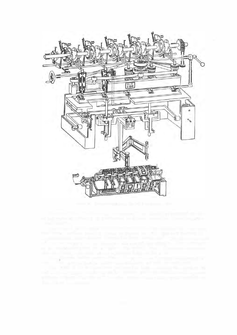
FIGURE  64.  Kinematic diagram of the  S-210 engraving machine 

D e c o r a t i v e   t e x t u r i n g   ( c h a s i n g )   or  tracing of patterns  on  the 

b rass parts  of  watche s ,   is  performed  on  special  machines befo re  or after 

electroplating. 

The S- 1 6 1A  s e ven - spindle  s emiautomatic  chasing m achine for  engraving 

rectilinear pattern  bands  is  shown in Figure  6 5 .   The  spindles  revolve  at 

1 2 , 000 rpm and  have  cutters  fastened to their lower  end.  The part  is  mount­

ed  on  a  carriage which is  displaced underneath  the  cutters .  The  part moves 

in the  horizontal  plane  at an angle to  the  spindle line .  The cutters  operate 

cons ecutively,  and  each leaves  a  pattern band  on the part. 

One  electric motor powers  two milling spindles  through a belt transmis ­

sion.  The  spindle feed is  0 . 0 07 - 0 . 05 mm / rev,  o r  2 0 0 - 6 0 0  m m /min. 

The  width  of the pattern  band produced is  determined by the angular  off­

s et  of the spindles  relative to the bed guides ,  while the width of each  separate 
pattern  element depends  on the radial offset of the  cutting point relative  to 

the  axis  of revolution. 

2 6 1  

Becaus e  of a  small  tilt  of  the  spindles ,  the  machining traces  have  the 

fo rm  of troughs  with  0 . 005 mm  maximum  depth. 

The parts ,  or  sets  of parts ,  to be  machined  are fastened on a block which 

is  clamped  in the  carriage .  The  carriage  is  moved  along the  bed  guides 

under the milling cutters by a  feed  s c rew.  The feed s c rew is  rotated by 

the  electric  motor  over  a  worm· reduction  gea r .  

FIGURE 

6 5 .  

General view  and kinematic scheme  of the S -161A semiautomatic chasing machine 

The  pattern  will  be  clear and  will  have a  good appearance if the  axial 

play  of the  spindle  does  not  exceed  0 . 005 m m ,   and  the  radial  run - out  does 

not  exceed  0 . 0 1  m m .  

I t  i s  recomm ended t o  perform  the  chasing  operation p rior to  electroplat­

ing,  with  the  condition that the tim e  interval betwe en  the  chasing and plating 

operations  s hall  not exceed  2  hour s ,   as  a  longer delay would lead  to  the 

oxidation  and  dulling of the  s urface and  to  the  deterioration of its  appearance .  

I f  the  chasing i s  p e rformed afte r  electroplating,  i t  frequently leads t o  the 

breaking of the  deposited  coat  and to  the  app earance  of yellow bands ,  which 

are  c enters  of  corrosion.  Corrosion follows  after a  certain  time  even if 

the breaking of the coat  is  invisible  to the naked  eye. 

2 6 2  

C h a p t e r  VII 

MA CHINING  THE  ESCA PE MENT  PA RTS 

The  escapement  consists  of the  leve r- escapem ent assembly  and  the 

balance  ass embly.  The  leve r - escapement  assembly includes  the  escape 

wheel  and  pinion,  the  pallet with pallet  stones,  the  guard pin  and  the  arbor .  

The  balance  assembly  consists o f  the  balance  with  staff and  screws,  the 

hairspring with  collet and  stud,  and  the  double  roller with  impulse pin . 

Locally produced escapement  parts  for watches  are  at present  made  of 

the following material s :   e scape  wheel  and  pinion,  pallet and pallet arbor o f  

U 1  OA  high - carbon  steel;  pallets o f  synthetic  dark- red  ruby;  and guard pin of 
LS6 3 - 3  bras s .   The balance  rim i s  made o f  MNTsS  6 3 - 1 7 - 1 8 - 2  nickel  sil ve r  

which  deforms l e s s  with  time  than  would  a  brass  rim .  Such  deformation 

introduces  an  error which  impairs  the  watch accuracy. 

The  hairspring is m ade of a  special  nickel alloy of ve ry low temperature 

coefficient.  The  temperature  coefficient  defines the  hairspring ' s  capacity 
to  maintain  a  constant mom ent  with  variation  of the  temperature .   The  tem ­

perature  coefficient  of  the  alloy  used  is  0 . 3  to  0 . 5  s ec / deg.  cent. ,  that  is , 

a  variation  of  1 oc  in  the  ambient temperature  produces  a  variation  of  the 

hairspring moment  causing an  error of  0 . 3  to  0 . 5  sec in  24  hours . 

THE  ESCAPE  WHEEL 

The  e scape  wheel  (Figure  1 )  must  s atisfy  stric  requirements  relative  to 

the  quality  of the  surface finish  on the  working faces  of the  tooth,  accurate 
geometrical  form  of the  tooth,  and minimum  run- out  with  respect  to the 

outside  diamete r .   The  tooth profile  is obtained by a  graphical plotting 

m ethod .  The  outer face  of the  tooth  ( 1 )  is  called  the  i m p u l s e   f a c e ,  
and the  inne r  face  (2 )  is  called  t h e   l o c k i n g   f a c e   (Figure  2 ) . 

The  impulse  face  and  the  l ocking face are  the  working faces  of  the  wheel, 

and they interact  with the pallet faces bearing the  same  names .   The sur ­

face-finish  quality  of these faces  must be  clas s  1 1  or  1 2 .   In  order to  facil­

itate the finish  grinding of  face  ( 1 )  and to  improve  the conditions  of the 

interaction between  the  wheel  and  the  pallets,  a  chamfer  ( 3 ) ,   about  6 0 o/o  of 

the wheel  thickness ,  is  removed from the lateral  side of the tooth . 

The  circular pitch  and  the  impulse-face length  must be  machined to  a 

tolerance  of  0 . 0 0 5 - 0 . 0 1  m m ,   and  the  tooth  run- out  on  the  outside  diamete r 

relative  to  the  pinion journal  must not exceed  0 . 0 1  m m .  

The  following operations  are  involved i n  the  machining o f  escape  wheels: 

blanking,  tooth milling,  piercing the  central  hole,  hardening and  tempering, 

2 6 3  

face  grinding  and  polishing,  and  finally  grinding  and  finishing  the  impulse 
and locking faces . 

The  wheel  is  blanked  out  of  a  polished  steel  s trip  (Figure  3 )  by a  die 

(see  Figure  2 1 ,   Chapter III ) .   The  teeth  are  milled  in  the  S - 1 09  seven­

spindle  semiautomatic  milling machine  (Figure 

). 

025!0.01 

FIGURE 

1. 

Escape wheel 

FIGURE 2.  Escape-wltcel tooth: 

1 -impulse  face ;  2-loci<ing face 
3-chamfer. 

FIGURE  3.  Escape-wheel blank 

The wheel blanks are copper- plated before the teeth are m illed .   The  copper 

layer on the two surfaces  acts  as  a  cushion  between the wheels  and improves 

the  cutting c onditions.  It has been established in practice  that the copper 

plating improves  the surface-finish quality  of the  milled  wheels by one class 

FIGURE 

4 .   S -1 0 9  

machine  for  milling escape­

wheel teeth 

• 

The  seventh  spindle  of the  machine  is free. 

(to  class 

7 )  

and  increases  the  life 

of the  milling cutter by  50  to  1 00 o/o 

(up  to  3 5 0  min ) .   The  blanks  are 

s tacked  on a  correspondingly  shape d 

mandrel  (Figure  5 )   in  stacks  of 

50  pieces  and  mounted  between  the 

centers  of  the  dividing  head  of  the 

machine . 

Each  of  the  spindles  on  the  S - 1 09 

machine carries a  fine - tooth  formed 

cutter,  whose dimensions and tooth 

form  are  given  in  Figure  6 .   Figure  7 

gives  the  sequence  of  the  tooth - form ing 

operations . 

The  milling allowance  for  the  e s ­

cape  wheel  of  "Pobeda "  watches  is 

0 . 1 5  mm  on  the  diam eter,  and  the  tol ­

e rance  is  0 . 02 - 0 . 03 m m .   The  tooth 

p rofile  is  rough-milled in  the  first 

three  ope rations ,  and finish- milled  in 

the  next three':' .  The  sixth  operation 

consists  in  the  finish  milling of the 

tooth  heel  and the  impulse  face .  

No  burrs  are  form ed on  the  tooth 

heel  in  these milling ope rations .  Each 

cutte r  m ills  all the teeth,  afte r  which 

the  spindle  barrel  is  indexe d .  

2 6 4  


Content   ..  64  65  66  67   ..