Technology of watch production - part 67
1
2
4 5
3
6
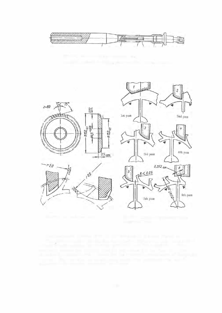
FIGURE 5. Mandrel for milling escape-wheel teeth:
1-mandrel; 2 -sleeve ; 3-clamping piece; 4-washer; 5- inscrt: 6-holder.
FIGURE 6. Fine-tooth formed cutter
FIGURE 7. Sequence of operations in milling
escape-lvheel teeth
The kinematic s cheme of the S - 1 09 machine is given in Figure 8 .
The electric motor rotates the driveshaft I (Figure 8 ), and, via a series
of belt transmissions, the milling spindle ( 1 ) and the cam shaft II. The
cam shaft rotates the dividing head (2 ) and moves the carriage ( 3 )
.
The
machine is equipped with a device for the automatic switchover of the spindle
barrel . Each spindle has an adjusting device for pos itioning the spindle
relative to the mandrel carrying the blanks .
2 6 5