Technology of watch production - part 55
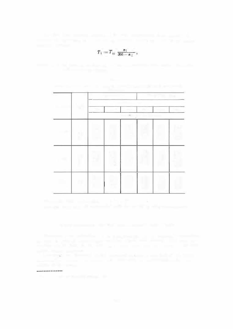
The idle time (corresponding to the idle movements of the machine ),
calculated acco rding to the following fo rmula, must be added to the basic
machining tim e :
where
n i =
the number of degrees o f idle- movement cam angle, according
to the operation sheet.
TABLE 2
Feed rates as a function of the required surface- finish quality for facing parts made of
LS63-3
brass
Tools
R9; RIB
Tools
VK8 ;
Tl5K6
'point
Surface-finish class required
" m/min
mm
'il\76
'V'V\}1
\l\7"76
'V\76
'il\7\71
'VWB
Feed rates
So ,
mm/part rev.
0
0 .020
0.0 1 4
0.009
0.022
0.0 1 7
0.012
0.3
0.021
0.0 1 5
0.0 1 0
0.023
O.D J 8
0.0 1 3
5 -30
0.5
0.023
0.0 1 7
0.0 1 2
0.025
0,020
0.0 1 4
0.8
0.025
0.0 1 9
0.0 1 4
0.026
0.021
0.0 1 6
1 .0
0.027
0.021
0.021
0.028
0.028
0.018
0
0.022
0.0 1 6
0.0 1 1
0.024
0.0 1 9
0.0 1 4
0.3
0.023
0.0 1 7
0.0 1 2
O.D25
0 .020
0.0 1 5
30-70
0.5
0.025
0.0 1 9
0.0 1 4
0.026
0.021
0.0 1 6
0.8
0.027
0.021
0.0 1 6
0.028
0.023
0,018
1 .0
0.028
0.023
O.Dl 8
0.030
0.025
0.020
0
0.023
0,0 1 7
0.0 1 2
0.029
0.023
0.0 1 8
Above
0.3
0.024
0.0 1 8
0.0 1 4
0.030
0.024
0.0 1 9
7 0
0.5
0.027
0.021
0.0 1 6
0.031
0.025
0.020
0.8
0.029
0.024
0.0 1 8
0,032
0.027
0.022
The piece time is the sum
T m
+
Ti
+
T aux
The auxiliary time is calculated with the aid of special s tandards •:' .
Setup Calculation for the S - 8 1A Semiautomatic Lathe
The setup is s o calculated as to complete during one camshaft revolution
the entire cycle of machining operations for the one s tation . The cam cir
cumference is divided into 3 6 0°, as was the case with the cams for the auto
matic screw machines .
The cams are mounted on the camshaft in ·such a way that at the initial
m oment the rollers, cam toes , and lever pins are positioned at the zero
points of the cam s .
• Standards of the Orgmashpribor Institute, 1954.
2 1 7