Technology of watch production - part 54


  Index      Books     Technology of watch production (Tarasov) 1964 year


Search            


Content   ..  52  53  54  55   ..


Technology of watch production - part 54


2 1 3  
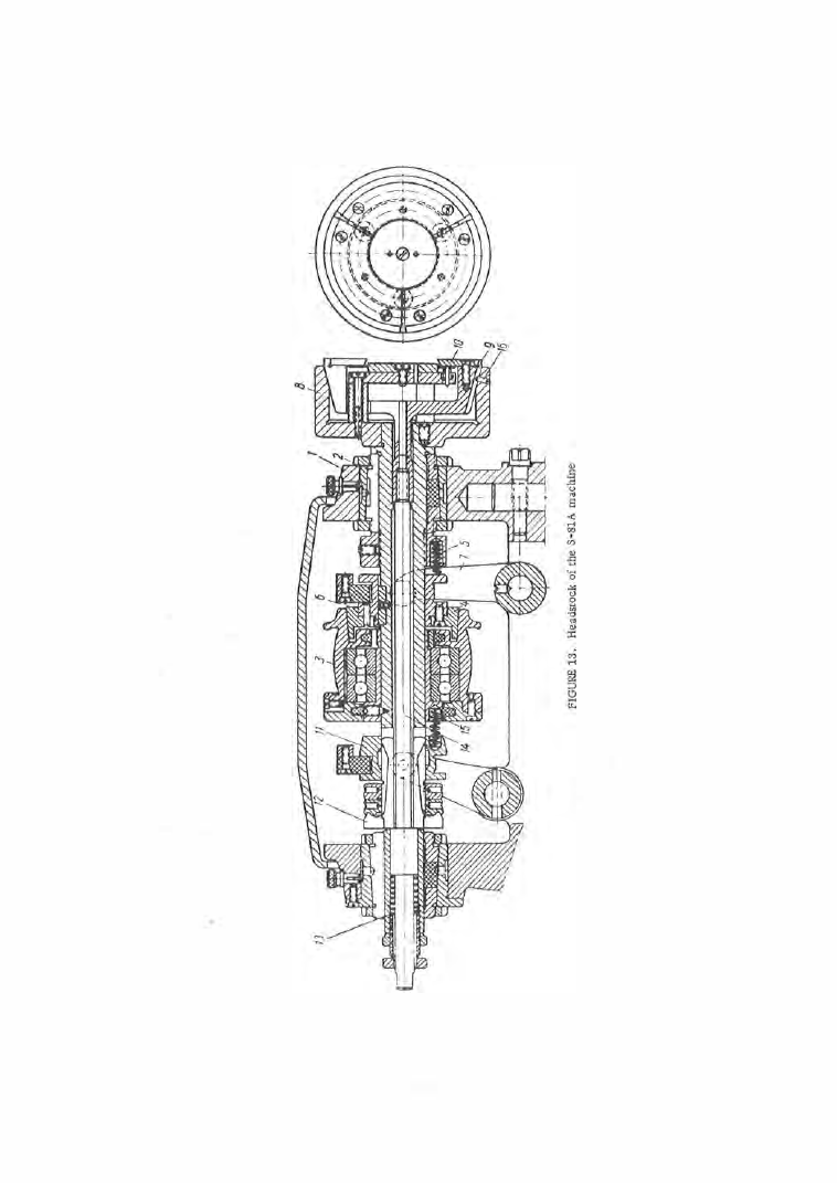
The  camshaft housing carries  guides  along which the  right-and l eft-hand 

slides  can move  longitudinally  (Figure  14 ).  The  tool  slides  in turn  have 
guides  for  the  cross  slides .  The  cross  slides  carry the  tool  holders  which 
can move  longitudinally  during tool  adjustment,  and are  afterward  fastened 

rigidly  to  the slide by  s crews . 

The  design  of  the  tool  holders  and  slides  makes  it possible  to position 

the  tools  accurately with  respect  to  diameter,  turning depth and c enter .  

Technical data,  S -81A semiautomatic lathe• 

N umber of spindles 

Maximum turning diameter,  mm  . . . . . . . . .  

Maximum thickness of the  part machined ,  mm  . 

Number of spindle  speeds  . . . . . . . . . . . . . .  

Range  of spindle speeds,  rpm  . . . . . . . . . . . .  

N umber of camshaft  speeds  . . . . . . . . . . . . .  

Range  of camshaft speeds,  rpm 

. . . . . . . . • . . .  

Longitudinal slide travel,  mm 

. . . . . . . . . • . .  

Transverse slide travel,  mm  . . . . . . . . . . . .  . 

Number of slides  . . . . . . . . . . . . . . . . . . . .  

Number of tools per toolholder  . . . . . . . . . . .  

Movement per division of the  slide  dial,  mm  . .  

Number of cams  . . . . . . . . . . . . . . . . . . . .  

Electric motor 

. . . . • . . . . . . . . . . . . . . . . . .  

50 

500-2820 

30 

0.5-7 .8 

30 

32 

0.01 

4+4 

0.75 kw, 

l OOO rpm 

The  production  rate  per spindl e  is an average of 2 0 0 0  operations per  shift . 

The  kinematic  diagram  of  the  machine  is  given  in  Figure  1 5 .   The 

electric - m otor  pulley  ( 1 )  powers  the  drive  pulley  (2 )  and  the  spindle 

pulleys  ( 3 )  and  (4 )  through a  flat belt.  Pulley  ( 5 ),  fitted on the  driveshaft 

together with pulley  (2 ),  drives  the  counter shaft pulley  (6 ) by a  round belt. 

The  countershaft,  in  turn,  drives  gears  ( 1 0) and  ( 1 1 )  on the  worm  shafts 

through gears  ( 7 ),  ( 8 )  and  ( 9 ) .  

Gear ( 1 0 )  i s  m ounted o n  the  right- hand worm  s haft together with  a  claw 

clutch.  The  worm  wheel  ( 1 3 ),  in m esh with the  s ingle- thread worm  ( 1 2 ),  is 

m ounted  on the camshaft as  are the  cams  ( 1 6 ),  ( 1 7 ),  ( 1 8 ),  and  ( 1 9 ).  The 

bell  cam  ( 1 6 )  controls the  slide  cross feed.  Cam  ( 1  7 ),  a  flat cam ,   feeds 

the  slide longitudinally.  Flat cam  ( 1 8 )  shifts  the  s tops for different machin­

ing depths .  C am  ( 1 9 ),  a  flat cam ,  automatically  disconnects  the machine 

spindle when the  machining  cycle  is  completed.  Gear  ( 1 3 )  has  a  pin  ( 2 0 )  

on its  face  which automatically disc onnects  the camshaft through  a  s ys tem 

of levers  connected with the  claw  clutch when the  machining  cycle  is  com ­

pleted . 

The  lever  arm  ratio  is  1 : 1  for cams  ( 1 6 )  and  ( 1 7 ),  and  2 : 1  for c am  ( 1 8 ). 

The  design and  kinematics  of  the  left-hand worm  s haft  and  camshaft are 

identical with thos e  on the right- hand  s ide.  The electric - motor pulley is 

a  change pulley which is  one  of a  s et  of 6  pulleys .  The  spindles  therefore 

have  6  speeds .  The  change  gears  ( 7 )  and  ( 8 )  give  5  speeds,  and  the  cam ­

shafts  accordingly have  3 0  rotation speeds  (see  Table  1 ). 

•  An improved version of the  machine ,  which is in the planning stage,  features a directionally adjustable 

spindle stop,  a higher motor speed,  and relief of the spindle of the radial stresses produced by the belt. 

2 1 4 

The S - 8 1A semiautomatic lathe is used for facing watch parts made of brass ,  

nickel silver,  and other  nonferrous  alloys .  Compressed  air,  taken  from  the 

plant  supply,  is  used as  a  c oolant.  The  lathe  is  als o  used for counterboring 

concentric  reces s es  or  for turning outside  shoulders .  The two spindles  are 

independent  so  that  a part can be  machined from both  sides  or  two  different 
parts  can be  simultaneously machined .   If it is  required  to machine  only 

one  side of one part,  the  s econd spindle  can duplicate  the  operation  of the 
first spindle.  The  mechanisms  giving the longitudinal  and  cross  slide  mo­

tions  for the approach and  retraction of the tools are combined  for both 

slides . 

FIGURE  14.  Slides of the S-81A machine 

FIGURE  15.  Kinematic diagram of the S-81A machine 

Parts  machined  on this  lathe  have  accurate  dimensions  and  a  good sur­

face finish,  because  of the  accuracy  with which the main as s emblies  of the 

machine  are built and  due to  the  use  of carbide- tipped tool s .   Depth  toler­

ances  of 0 . 0 1 5  mm  can be held as  well  as  tolerances  of  0.03 m m .   The  quality 

of the  surface  finish  corresponds  to  class  7 - 8 .  

The  cutting conditions  for facing and counterboring recess es  in plates 

and  cocks  (bridges )  are  determined as  a  function of the  machining diameter, 

the depth of cut,  the required surface  finish,  and the tool  quality. 

2 1 5  

T h e   c u t t i n g   s p e e d   is  calculated  on  the  basis  of  the  maximum  ma­

chining  diameter.  The  cutting speed corresponding to the  maximum  spindle 

speed, 

n =  

2 82 0  rpm ,   and  the  maximum  machining diameter,  50 mm,  is: 

"D·n 

tJ  = 

1 000 

450 m /min . 

For the  "Pobeda"  wristwatch plate,  having 

2 6  mm,  the  cutting speed 

will  be 

_  3 . 1 4 ·  2 6 · 2 8 2 o  

2 2 5  

I  . 

0 -

1 0 00 

::;:::: 

m  mm .  

It is  recommended  that  the  maximum  cutting speeds  (i. e .   those corre­

sponding to 

2 8 2 0  rpm ) be us ed in machining plates  and  cocks ,  as  the 

material  from  which  they are  made,  LS6 3 - 3  leaded bras s ,  has good mach in-· 
ability. 

TABLE 

Camshaft speeds,  rpm,  of the S-81A machine 

Spindle  rpm 

Steps of 

Change gears 

camshafts 

500 

705 

1000 

1410 

2()00 

2820 

Camshaft rpm 

48 

36 

0.51 

0.73 

1 .03 

1 .46 

2.06 

2.92 

44 

40 

0.76 

1 . 1 0  

1 ,55 

2.20 

3 . 1 0  

4.40 

40 

44 

0.945 

1 .32 

1 .89 

2.64 

3.78 

5.28 

36 

48 

1 . 1 4  

1 .61 

2.28 

3.22 

4.56 

6.44 

28 

56 

1 .38 

1.95 

2.76 

3.90 

5.52 

7.80 

The  feed rates  are  established  as  a  function  of  the  required s urfac e ­

finish quality and  the  radius  o f  the  tool point.  The  s urface - finish  quality 

increases  with  the  increase in the  tool-point  radius,  but  this  is  accompanied 
by an  increase  in the  cutting forces which can lead  to  the  deformation of 

the part . 

The  surface - finish quality  of  the  tool  cutting s urfaces  must be  better by 

one  o r  two  classes  than  that  required of the  machined  surfac e .  

The  feed  rates  f o r  machining  LS6 3 - 3  brass  are  given i n  Table  2  a s  a 

function  of  the  required surface - finish quality  and  the  cutting speed. 

The  machining time 

T

is  determined from  the  formula 

whe re 

T

machining  (basic )  tim e ,   min; 

length  of the  machine  surface,  mm; 

l1 

tool approach,  mm; 

l2 

tool  o vertravel,  mm; 

speed,  rpm ;  

s  = 

feed p e r  revolution,  mm . 

2 1 6  


Content   ..  52  53  54  55   ..