Technology of watch production - part 24


  Index      Books     Technology of watch production (Tarasov) 1964 year


Search            


Content   ..  22  23  24  25   ..


Technology of watch production - part 24


9 3  

0.. 

"'' 

"' 

</) 

"' 

"" 

carrying  the  upper die  shoe.  The  m otions  of the  rams  are  of cours e  coor­

dinated .  

The  outer  ram  i s  actuated by  the  c rankshaft  through  cam s ,   rollers  and 

rods ,  or by a  pneum atic  device .  

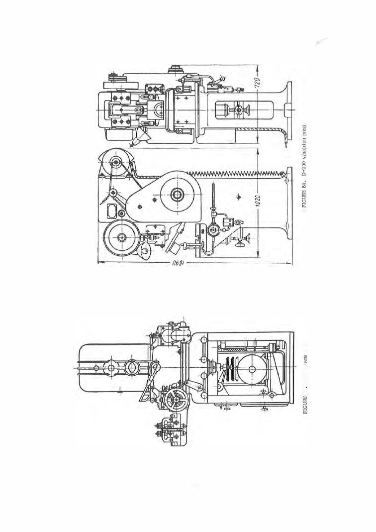
FIGURE 5 5 .  

Kinematic scheme o f  the  D-200  vibration  press 

The  inner  ram  is  actuated by  an  ordinary  crank  mechanis m .   In d raw­

ing,  the outer ram  clamps  the blank before  the  punch  on the  inner  ram has 

desce

n

ded and  begun  the  d rawing and  holds  it until  the  drawing punch  leaves 

the part .  The  outer  ram  is  im mobilized during the  drawing proces s .  

Double - action presses  are  well  s uited for  combined blanking and  draw­

ing.  The blanking punch is  m ounted on the outer  ram  and  s erves  as  blank 

holder as  well. 

Multiple - station 

presses  are used in  the  mass production  of parts  whose 

manufacture  requires  several  similar  ope rations,  mainly  d rawing .   Finished 

alarm - clock cas e s ,   fo r  instance ,   can  be  obtained  directly from  the  strip 

on  such presses .  Alar m - clock cases  have  relatively large  dimensions , 

and  were  the  5  o r  6  stamping operations  to  be performed  on  separate  pres ­

s e s ,   considerable  floor space  and  staff  would be  needed. 

F riction 

presses  are us ed fo r  straightening,  stamping,  bending and 

d rawing.  A  press  of this type  is  s hown  in  Figure  5 6 .   Two brackets  with 

bearings  s upporting a  s haft  with  two  vertical  friction  disks  are  mounted  on 

the  press  frame .   The  s haft with  the  disks  is  powe red by an electric  motor 

through a  belt transmission.  The shaft can move  freely in its axial  direc ­

tion  and  thus  bring  either  the  left-hand  or  the  right-hand  disk into  contact 

with a flywheel on a  vertical  s c rew.  The  flywheel  is  leather-surfaced and 

the  ram ,  restrained by lateral  guides ,  is  raised and lowered by the  screw 

which turns  in a nut mounted on the upper pa rt  of the frame .  

The  die  set is  m ounted o n  the  press  table. 

When  the press is  started,  the  shaft  carrying the  vertical  disks  rotates 

and  one  of the  disks  is  made  to  contact  the  flywheel .  The flywheel turns  the 

screw in  the  fixeu nut forcing  the  ram  downward.  At  the  beginnir_g,  when 
the  flywheel  contacts  the  vertical  dis k  at  a  small  radius , the  rotational  speed 

of the  flywheel  is  small.  A s  the  flywheel des cends with the ram ,  the radius 

increas es  so  that  the  ram  has  a  maximum  velocity  at  the  end  of the  stroke . 

By  this  time  the  flywheel  has  accumulated a  large  amount  of  ene rgy  which 

9 4  

it t ransfers  to  the  part  to be  worked through  the  s c rew  and  the  ram .   In its 

lowest position  the  ram  frees a  spring which  b rings  the  s econd  ve rtical  disk 

FIGURE  56 .  Friction press 

(through  a  system  of levers )  into  contact 

with the flywheel .  This  reve rses the 

direction of  rotation  of the  flywheel  and 
raises  the  ram . 

The  s hortcomings  of  friction presses 

are their low p roductivity and poor ac ­

curacy.  The  height  of  this  type  of  pres ­
ses  relative  to  their powe r  is  exces sive . 

Knuckle-joint p res s es  are  used for 

embossing operations . 

The m ain dif­

ference between these  p res ses  and 

ordinary  c rank press es is that in knuckle­

joint p resses the  ram  is  connected to 

the  crankshaft  through an additional 

linkage  (Figu re  5 7 ),  which  generates 

cons iderable forces . 

The  force  Q  developed  by  the  crank 

mechanism  and  applied  to  the  point 

of 

the linkage  creates  a  force 

directed 

perpendicular  to Q, and in oppo site  direc­

tions .  The  force applied  to the ram can 

be  taken  as 

tan 

a .  

Because o f  design  considerations  the 

angle 

Gt 

at the  end  of  the  stroke  mus t not 

exceed  87° 3 0 ' .   In  this  position we  have 

mar. 

tan 

87°30' 

� 

1 .5 Q .   In other 

wo rds ,  the force obtained is almost  1 2  times  as large  as  the  force on  the 

cranks haft .  The  gain  in  force  is  of  cours e  associated  with  a  corresponding 

reduction in distance  t raveled.  Knuckle- joint p resses have  the refore a 
relatively short  s troke  and  also  a  relatively  small  number  of  s trokes  per 

minute  ( 3 0 - 5 0 ). 

Figure  5 8  gives  a  general  view  of  the  knuckle- joint press  made by  the 

East- German firm  DIA . 

Hydraulic 

p resses  s erve  the  sam e  purpose  as  knuckle -joint  presses . 

They  are  used in  watch production for  emboss ing  relief figures  and  sym ­

bols  on  dials ,  and  for other similar ope rations . 

Safety  rules  must be  strictly  obse rved  when  ope rating p resses .  The 

press  design  must  include  a  two - hand  starting lever,  protection shields 

on  the  working parts  of the pres s ,   devices  preventing the introduction  of 
hands  into the  danger  zone during the  motion  of the  ram,  etc.  The  die  sets 

must  also be  shielded,  and the shield  to  be us e d  must be indicated on the 

die - s et  d rawings . 

The  s m allest  defect in  the  operation  of  the  p ress 

mediately  reported,  and work on the  press  stopped. 

se rvance  of all  safety  rules  can  prevent  accidents . 

9 5  

o r  die  set  must be im ­

Only  the  careful  ob-

The  operator must  be  familiarized  with  these safety  rules  before  he  is 

put  to  work with p resses and his  knowledge  of them  should be  refres hed 
periodically. 

FIGURE 

57 . 

Diagram of the  crank  mechanism 

and the  linkage  of a  knuckle-joint  press 

9 6  

FIGURE  5 8 .   Knuckle-joint  press 

DIA ,  made  in  Eastern Germany 


Content   ..  22  23  24  25   ..