Technology of watch production - part 22
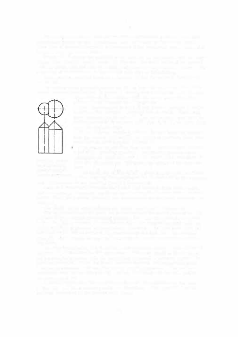
Figure 4 0 , c shows an indentation with a cylindrical portion. The drill
is initially guided by the cylindrical part, and later by the conical part.
This type of center-pointing is recommended for diam eters above
1
mm and
in parts 3 mm or more thick.
Figure 40, d shows the position of the drill in an indentation with an angle
larger than the drill -point angle. In this case the drill contacts the crater
with its point, and not with the cutting edges as in the preceding cases . The
accuracy of drilled holes is lower with this type of indentation .
The required p ointing depth is a function of the diameter of the hole to
be drilled.
The points mus t protrude above the die by 0 . 3 - 0 . 5 mm more than their
actual desired penetration, in order to ensure that a clearance will always
e xist between the work and the die fac e , preventing dan
gerous "dead" impacting of the
.
pres s .
Hole diameters are divided into s everal groups in order
·
-
-
-
to reduce the variety of pointing-punch size s . Thus, only
three pointing-punch sizes ( 1 , 1 . 8 , and 2 . 5 mm ) are used in
drilling holes of diameters 0 . 5 0, 0 . 6 , 0 . 7 5 , 1 . 1 0 , 1 . 2 0, 1 .4 0 ,
1 . 8 0 , 2 . 0 and 2 , 2 0 mm .
If the distance between centers for two holes is smaller
than the s um of the radii of the pointing punches , flats are
machined on both punches (Figure 4 1 ).
The design of pointing dies mus t allow for easy replace
ment of the pointing punche s . F re quent replacement is
necessary as metal adheres to the punch point and sp reads
FIG URE
41.
Mount-
over the cone s urface, dis torting the s hape of the indenta-
iug of the pointing
tions .
punches for small dis-
tances
be
tween centers
The accuracy of the center punching must not be affected
by the frequent dism antling of the die s et and by the removal
and replacement of the p ointing punches themselve s .
Repeated grindings o f the pointing-punch tips reduces their total length
and it eventually becomes insufficent fo r forming the indentations . In s uch
cases either the pointing punches are replaced o r the die-plate thickness is
reduced.
The most widely used pointing-die design is shown in Figure 4 2 .
The hardened - s teel die plate ( 3 ) is mounted o n the lower shoe of the die
set and in it are fixed the pointing punches (8 ). The die plate is connected
to the disk ( 6 ) by screws ( 7 ) and the pin ( 9 ) . The s upporting pins ( 1 0 ), o n
which the p art i s placed, are mounted i n the disk. The knock-out pins (5 ),
actuated by the knock- out bar (4 ), pass through the disk (6 ) . The nesting
pins (2 ), which locate the part in the horizontal plane are mounted on the
die plate.
The flat- faced punch ( 1 ), provided with clearance holes to take the nest
ing pins (2 ) is mounted in the upper s ho e . When the punch i s lowered, the
part des cends together with the s upporting pins and is pressed against the
pointing punches . When the punch recedes upward, the s upporting pins ,
being spring-loaded, lift the part off the pointing punches . The part is
remo ved from the nesting pins by a p edal, the knock- out bar (4 ), and the
knock- out pins ( 5 ).
It might happen that the longest punches are concentrated on one side
of the die, and the sho rtest punches on the other. The supporting pieces
p revent dis tortion of the part in s uch cases .
85