Technology of watch production - part 19
 

  Index      Books     Technology of watch production (Tarasov) 1964 year


Search            


Content   ..  17  18  19  20   ..


Technology of watch production - part 19


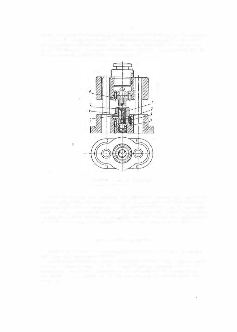
A t  the  beginning  the  descending die  (8 )  presses  the  part agains t  the  s tripper 

( 7 )  which is  thereby forced  down,  comp ressing the  sp ring  (4 ) .   The  punch 

( 5 )  then pierces  (or calibrates )  the  hole .   The  slugs  pass  through  the  hole 

in  the  die  (8 )  and in  the  uppe r  s hoe and  are  ejected .   The  centering  nest ( 6 )  

is  also lowered,  compressing  the  springs 

( 3 ) . 

FIGL:RE 

2 5 .   Piercing die  for  piercing  a 

central hole  in gears 

A fter the  hol e  has  been pierced,  the  upper shoe  retracts  while  the  center­

ing nest ( 6 )  and the s tripper ( 7 )  return to  the ir  original  positions  under the 

action of their  resp ective  springs .  The  part  is  removed with the  aid of pin­
c e rs .  Having a  run- out  of  not  more  than  0 . 0 1 5  m m ,   the  central  hol e  pierced 

by this  die is  more  conc entric  than  thos e  made by the form erly us ed m ethod 

of d rilling or  bo ring  on a  machine  with  the  wheel  clamped in  a  collet. 

DlNKING,  SHAVING,  AND  BENDlNG 

Dinking 

is  a  process  for  blanking parts  from  mica,  leather,  cardboard 

and  other thin  nonm etallic  materials . 

The  clinking  process  consists  in cutting  the  m aterial  with  a  hollow punch 

having a  closed contour .  The  die  is  cons tituted by a  s m ooth  l ead o r  mil d ­

steel plate .  The punch i s  hardened t o  

Rc 

= 52  to  56  and  the  ma rks  left  by 

the  punch  on  the  s urface  of  the  die  are  removed  at  certain  fixed  time 
intervals . 

7 3  

Typical  punch  designs  for  dinking dis ks  and  washers  are s hown  in Figure 

2 6 .   The punch  s hear angle 

is  1 5  to  1 8° .  

Shaving. 

Parts  blanked  from  s tock more  than  0 . 5  mm  thick  will  have 

rough  edges  and burrs . 

Most watch parts  are  required  to  have  a  smoothly finished s hear ..surface 

(class  7 - 8 )  perpendicular to  the  main plane  and  the parts  are  shaved afte r 

blanking  to  achieve  this  finish.  Shaving allowances  are  given in  Table 

3 .  

These  allowances  should b e  increas ed by  50- 6 0 o/o  a t  s harp  angles  and  sharp 

transitions  where burrs  are  liable  to  attain  dim ens ions  as  large  as  50 o/o  of 

the blank  thicknes s .   The  allowances  are also  increas ed by  0. 5  to  0. 8 o/o  of 

the major blank  dimension  when  this  dimension is  larger than  2 0 mm .  

FIGURE 

2 6 .  

Dinking dies : 

FIGURE 

2 7 .  

Sh

-

0 3  

shaving die 

a-for  disks;  b-for  washers 

Parts  may be  shaved  on  both  their exte rnal  and  their inte rnal  contours . 

The  part  to  be  shaved in  the  die  set in  Figure  2 7  is  placed on  the  die 

( 3 )  

and 

properly located by  the  nest  ( 2 ) .   When the  punch  ( 1 )  is  lowered,  the  part 

is  forced  through  the  die  opening  whose  cutting  edges  shear the metal  along 

the  desired contour. 

TABLE 

Shaving  allowances for 

20 

mm-diameter  blanks  (total for both sides) 

Material 

Part  thick-

1\lild steel  and  brass 

Steel of aver age  hardness 

Hard steel 

ness 

min 

max 

min 

max 

min 

max 

0 . 5- 1 . 5 

0 . 1 0  

0 .1 5  

0 . 1 5  

0 .20 

0 . 1 5  

0 .25 

1 .6 - 3  

0 . 1 5  

0 .2 0  

0 .2 0  

0 .25 

0 . 2 0  

0 . 30 

3 .1 - 4  

0 . 2 0  

0 .25 

0 .25 

0 . 3 0  

0 .2 5  

0 . 35 

-L�- 5 .5 

0 .2 5  

0 . 3 0  

0 . 3 0  

0 . 35 

0 . 3 0  

0 .40 

7 4  

In  o rder that  the  allowanc e  be  uniformly  removed,  the  nest ( 2 )  mus t  be 

accurately pos itioned  relative  to  the  die contour,  and it  is  therefore punched 
in s itu by  the  shaving-die punch its elf  after which  the  opening is  enlarged 

by the  value of the allowance,  and chamfe red . 

In  watch p roduction  it  is  frequently  necessary  to  blank  and  shave  parts 

whose thickness  is  2 - 5  times  their width  or  diameter.  In  such  cases  the 

blanking allowance  is  inc reased,  and the  blank  is  s haved  on  a  die  s et  having 

a  punch  la rger  than  the  die  opening. 

In  this  type  of shaving  die  the  punch  does  not penetrate  into  the  die,  and 

each  part  is  ejected  from  the  die by  the  following  part .  A  surface  thus 

s haved has  a  bette r  finis h,  and  the  part  is  flatter,  but  the  shaving force  re­
quired  is  much large r  than  that  required in  shaving by the  usual  method. 

Springs  of  s top  watches  (see Figure  1 0 )  are  shaved by this  method. 

When the  contour  of a  part  se rves  as the  bas e  for subsequent operations 

parts  may be  s haved  two  or  three times .  E

a

ch

subsequent s having opera ­

tion  removes  a  s maller and m o r e  even laye r  and  the  dies  us ed i n  the final 

shaving  must the refore be  much  more  rigid  than  the  firs t  shaving die .  

Multiple  shaving p roduces  more uniform  dim ensions  and  a  better s urface 

quality.  The  parts  mus t  be shaved in the same direction in which they were 

blanked,  as  otherwise  burrs  will  appear on the edges . 

Thin  s teel parts  are  frequently sized ins tead  of being shaved  and  this 

p rocess  pro duces  a  clas s  9  or  1 0  finish  on the  lateral s urfaces .  In sizing, 

the working  edl;{es  of  the  die are  blunt,  and  as  a  result the  part increases 
in  thickness  (Figure  28 ). 

FlGUHE  ZR. 

Schematic representation of the sizing 

process 

The  s having force 

is  calculated from  the formula 

P = kl · ® s , 

where 

perimeter,  mm; 

a  = 

allowance per side,  mm; 

a 5 " 

shear  strength,  kg/mm2; 

k  = 

coefficient  allowing for the  ejection force  Q  and  the  shaving depth 

h .  

For s teel  with  an  ultimate  s trength 

au � 

90 kg/mm2 ,  k "  1 . 5  to  1 . 6 ;   fo r 

b rass  with 

a u 

up  to  6 0 kg/ mm 2 

k "  

1 . 2  for a  s tock thickness  of  1  mm . 

Example.  lt  is requireu to determine  the  force ? necessary  for  shaving  a watch  plate  38 n!ln  in diameter 

and 

:! .2 

mm  thick .  Table 

3, 

after adding 0 . 8 °/o D ,   recommends  an  allO\vance  of 0 . 52 mm.  Further  given are 

a5 

=  3H kg/mm2  and 

k =  1 .4.  11/e  therefore  obtain P = 

1 .43X3 .14X38X 0 . 52°X38 

3.4 

t .  

The force 

P required for  sizing  is higher  by  30"/o than that required for shaving and  a minimum al101vance 

of 0.03 to 

O .OH 

mm  per  side  is fi xed. 

• 

[The  value  0 .52,  taken from  Table  3 ,   constitutes the total  al101vance ,  i . e . ,  2 a.  As,  however,  the  above 

formula  operates with the  al101vance  on  one side  only,  i. e .   w ith  a,  it  seems  that  0 .26 should  be  substituted 

for  0.52 ,  which  of course  would  reduce  P  to 

1 .7 

t . )  

7 5  

The  same  die  s ets

.

are  used for shaving dies  as  a re  us ed for blanking 

dies  (Figure  2 7 ). 

Dies  with  a  fixed  nest are  us ed for  shaving parts  of  thickness  up  to  1 m m .  

Thicke r  parts  are  s haved on dies  with s wing- out  nests  (Figure  2 9 ) . 

The  nes t  is  first s wung clear  of  the  wo rking  zone  of  the  die  s et  and  the 

die  is  carefully  cleaned,  rem oving all  chips .  The  part  to  be  shaved  is  then 

ins e rted into  the  nes t .   The adjus tm ent  of the  die  s et  (the positioning  of  the 
punch  relative  to  the  die )  is  much  eas ier with  s wing- out nests .  On  the othe r 

hand,  it  should  be  kept in mind  that the positioning accuracy o f  swing- out 

nes ts  is  inferior to  that  of fixed nests  and  that,  with s wing- out  nes ts ,   the 

shaving  action m ay be nonuniform.  Accidental  notching  of s wing-out  nests 
is  a  possibility  to  be  reckoned  with . 

FIG URE  2 9 .  

Swing-out  nest  for  a  shaving die 

FI GURE 

30. 

Combination  blanking- shaving die 

It  should  be  mentioned  that,  according to  safety  rules ,  parts  may  be  fed 

into  fixed nests  with pince rs  only. 

C ombination  blanking- s having  dies  are now widely us ed in watch produc ­

tion. 

The  des ign  of such a  combination die for plates  and  b ridges  is  shown  in 

Figure  30.  The  uppe r  shoe of the  die set carries  the punch  ( 1 )  and  the  s t rip ­

per (2 )  and  on the lowe r  shoe are mounted  the  blanking  die  (3 ),  the pads (4 ), 
and the shaving die  ( 5 ) .  

The  first time  the  punch  ( 1 )  descends ,  the  s t rip  i s  p ressed against  the 

die  block  by  the  s tripper  (2 ),  a  part  is  blanked,  and  remains  in  the  die. 

The  s econd  strike  of the punch blanks  anothe r  part and the first part is 

pus hed into  the hole in the pads  (4 ).  During the third blanking the first part 

is shaved by the die ( 5 ) .   The shavings  are  removed by a  jet  of compressed 
air  through a  lateral  window between the pads .  The  two  dies ,  togethe r  with 

the  pads,  are  a  single  ass embly and  are  mounted  on  the  lower shoe . 

7 6  


Content   ..  17  18  19  20   ..