Technology of watch production - part 18
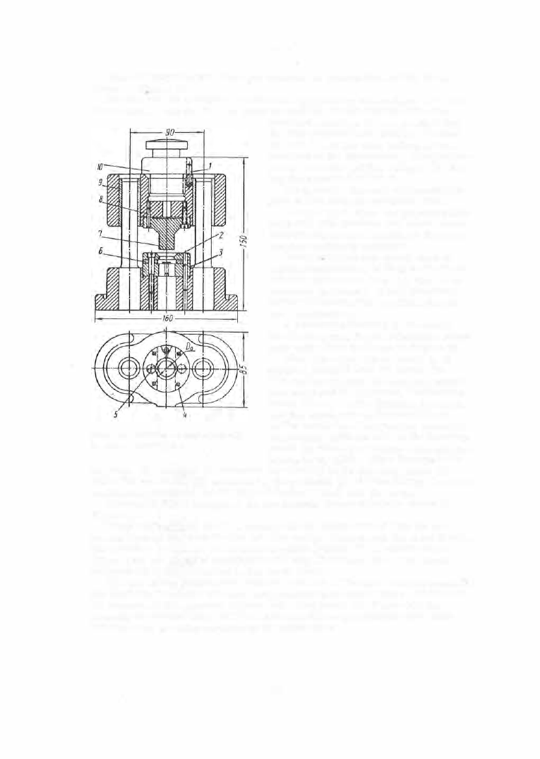
This die operates with two side cutters . A general view of the die is
shown in F\gure 1 9 .
The die has no guidepins , punches being guided by the s tripper ( 1 ) which
is mounted on the die (2 ). In order to increas e the durability of the die,
FIGURE
1 7 .
Model Sh-02 blanking die with
fixed-type lm"er stripper
hardened bushings ( 3 ) are p ressed into
it. The piercing and blanking punches
(4 ) and ( 5 ) and the side cutters ( 6 ) are
fastened to the upper shoe. The punches
neve r leave the guiding stripper ( 1 ) dur
ing the operation of the die .
Progressive dies are o f a much s im
pler design than are compound die s .
C o m p o u n d d i e s are us ed for blank
ing parts with windows and holes where
an accurate mutual location of the holes
and the contour is required.
Compound dies are widely used in
watch m anufacture, as they m ake it pos
s ible to blank parts to a high degree of
accuracy ( 0 . 02 mm ) . Their s hortcom
ing lies in the complexity of their design
and manufacture .
A schematic drawing of the model
Sh- 04 compound die for blanking a round
part with a hole is shown in Figure 2 0 .
When the uppe r die i s lowered, the
s tock is pressed onto the lower die.
The spring s trippe r (4 ) des cends s imul
taneously with the upper die , the blanking
punch ( 5 ) and the die ( 3 ) blank the part,
and the knock- out (6 ) is pushed back.
At the same time the piercing punch (2 ),
cooperating with the hole in the blanking
punch ( 5 ) which constitutes a die, pierces
a hole in the part. When the upper die
is lifted, the s tripper (4 ) removes the stock from the blanking punch (5 ),
while the knock- out ( 6 ), actuated by the push pin ( 1 ) and the spring ( 7 ), ejects
the blanked p art from the die ( 3 ) and forces it back into the s trip .
The model Sh- 06 compound die for blanking b rass wheels is s hown in
Figure 2 1 .
The blanking punch ( 6 - 7 ) is mounted in the lower shoe of this die and
s erves als o as piercing die for both the s ector windows and the central hol e .
The punch is compos ed of the contour punch (Figure 2 2 , a ) and the core
(Figure 2 2 , b ), clamped together by the ring ( 5 ) (Figure 2 1 ). The s tock
s trippe r (4 ) is also mounted in the lower shoe.
The die ( 3 ) for blanking the external contour of the part, and the punch (2 )
for blanking the s ector windows , are mounted in the upper s ho e . The punch
(2 ) consists of five s ectors (Figure 2 3 ). The punch ( 1 ) (Figure 2 1 ) for
pie rcing the central hole, and the knock- out ( 8 ) for p ressing the part back
in
t
o the s trip , are also mounted in the upper s ho e .
6 9