Technology of watch production - part 14
 

  Index      Books     Technology of watch production (Tarasov) 1964 year


Search            


Content   ..  12  13  14  15   ..


Technology of watch production - part 14


The  apparatus  is  s uitable  for  tes ting round bars  of  diameters  from  0 . 8  

t o  7 mm and

'

flat bars  o f  a  thickness  of up  t o  5 mm . 

A  counter  ( 5 )  records  the  number of  bends . 

FIGURE  1 1 .   Apparatus for torsion-testing of wires 

T o r s i o n   t e s t s   f o r   w i r e   are  conducted on the K - 1  (K - 2 ,  K- 3 )  ap­

paratus  (Figure! 1 1  ). 

The  wire  is  clamped  in  chucks  in the  head- and  tailstock of the apparatus . 

The  heads tock  chuck  is  rotated by  an  electric  motor which  is  automatically 

switched o ff  when  the  specimen fails .  The  numbe r  of  turns  to  failure  is 

recorded on a  counter. 

R e s i d u a l   d e f o r m a t i o n   (permanent- set) t e s t s .   With heat- treated 

sprin

s teel s trip s ,   the tensile ,   hardness and bending tests are only indirectly 

FIGURE 12. Apparatus for testing the elasto­
plastic  properties of spring steel strips 

indicative  of  their quality,  and  do  not  define 

fully the  e"lasto -plastic p roperties  of the 

m aterial . 

Thes e  p roperties  are  dete rmined  by us e 

of  an  apparatus  (Figure  1 2 )  which measures 

the angle 

a. 

of  res idual  deformation.  The 

apparatus  s cale  is  divided into  1 8 0°.  The 

test  specimen is  clamped at  one  end to  the 

mandrel  of the apparatus ,  and  the  other  end 
is  s et  to  the  zero point  of the s cale .   The 

test  specim en  is  then wrapped around the 
mandrel  by an angle  of  1 8 0°.  After  50  s uch 

b ends  the  angle 

a. 

is measured from the 

position of the  tes t  specimen on the  s cale ,  

and  the  res idual  deformation  determined 

from  it. 

In some variants  of this apparatus  the 

springback angle 

(  � 

1 80° 

-a. 

0) 

is  m easured 

ins tead of the  angle of res idual defo rm ation .  

The  accuracy of this  type  of apparatus  is 

by  5  to  6° lower than  that of the  device 

shown in Figure  1 2 .  

5 3  

The  springback p roperties  for s trips  are  given in  the  ChMTU  3 6 8 0 - 5 3  

specifications .   The  angle  o f  springback  for a  0 . 1 2  m m  thick  s pring bent  on 

a  5 mm  diameter mandrel  must  not be less than  1 4 7 ° .   For a  0 . 32 mm strip 

on  a  2 0 m m  diameter mandrel ,  this  angle  mus t  not be less  than  1 5 6° (for 

first- grade  strip s ) .   C orrespondingly,  the angle  of  residual  deformation 
mus t  not be larger  than  3 3°  for  the  0. 1 2  mm  s trip,  and  24°  for the  0 . 32 mm 
strip . 

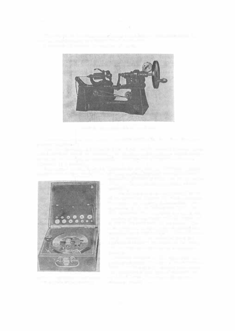
M a c h i n a b i l i t y  t e s t   f o r   m e t a l s .  The  m achinability  test is  con­

ducted  on the apparatus  shown in  Figure  1 3 .  

FIGURE 13.  Apparatus for testing of metals for machinability 

The  test consists  ess entially  in producing dimples  (craters )  in the  metal 

by m eans  of a  pointed- end d rill  of 2 . 5 - 3 . 0 mm  diameter and  a  point  angle 

of  8 0 - 8 5°  for  bras s ,   and  1 2 0 - 1 2 5°  for  steel. 

The dimples  are drilled under a  specified  axial  load on the d rill  which 

is  m ade to  rotate  for a  given number of turns .  After the  chips  have  been 
removed,  the  diameter  of  the  c rater is  measured by  m eans  of  a  graduated 

magnifying glass .   The  m achinability  can  also be determ ined f rom  the  weight 

of  chips . 

The  machinability  of  a  given m etal  is  determined as  a  perc entage  of  the 

m achinability  of  an accepted s tandard  m aterial .  The  above  m ethod  is  there­

fore of a  comparative  character. 

Num erical  values  of the s quared  ratios  of the diameters  of the specimen 

and standard  c raters ,  respectively,  are  given in a  special  table .  

The  apparatus  consists  of a  s emiautomatic bench drilling p ress  and  a 

cam  mechanism .  

54 

The  constant  ( given )  load  is  applied by  calibrated weights  carried by the 

spindl e .   The  specified number  of  turns  of  the  s pindle for one  test cycle  is 
ensured by a  cam  mechanis m  lifting the  s pindle  off  the  s pecimen.  The load 

can be  varied,  depending upon the thickness  and machinability  of the  material 
being tes ted. 

M e t a l l o g r a p h i c   t e s t s  consis t in the  inves tigation  of the  micro ­

structure o f  metals  and  alloys b y  m eans  o f  suitable  (metallographic )  mi­
croscopes . 

55 

C h a p t e r   III 

STA MPING  PROCESSES 

Stamping is  one  of the  most advanced m ethods  of m etal  processing and 

has  m any  advantages  over  other proces s ing m ethods  s uch as  turning,  milling, 

drilling,  etc .  Complex parts  can be  stamped out in one s troke  of the p ress 

to high  accuracy and with  stable  dimensions .  Stamping process es  are  char­

acterized by  a high output:  various presses have between  60 and 4 2 0  work­

ing strokes  per  minute.  Almost all kinds  of s tamping operations  can be 
automatized . 

Stamping processes play  an impo rtant part in watch production.  Of the 

6 2 0  machining operations  carried out  on wristwatch parts ,  1 2 5 ,   or  2 0 %, 

are  stamping operations .  The  amount  of  work expended  on  thes e  operations , 

howeve r,  repres ents  only  7 %  of  the  total  work  exp ended  on  all  the  machin­
ing operations . 

Stamping refers  to  the  various  technological operations executed ( general ­

ly  without formation of chips )  on p resses by m eans  of s tamping dies  of  var­

ious  designs .  The  following s tamping processes  are  us ed in watch p roduc ­

tion:  blanking,  pie rcing,  dinking,  shaving,  bending,  d rawing,  straightening, 
center punching,  embossing and coining,  marking,  forming,  combined 

punching,  and  sizing . 

Thes e  operations  are  executed  on crank,  knuckle,  friction  and  hydraulic 

pres s e s .  

The  dies  used i n  stamping operations  are  known,  according t o  the  oper­

ations  executed by them,  as blanking dies ,  s having die s ,   etc . 

BLANKING 

AND 

PIERCING 

Blanking is  the  most widely applied among the  stamping operations  and 

is  the  initial  operation  in  the  manufacture  of  parts  from  flat  bars  o r  s trips . 
It  is  applied not  only  as  a  s eparate  operation,  but  also  in conjunction with 

other  s tamping ope rations . 

The  blanking p rocess  is  shown diagrammatically in Figure  1 .  

The  blanking process  can b e  divided into  three  s tages  (Figure  2 ) .  

F i r s t   s t a g  e .   When the p r e s s  ram  is  lowered,  the  flat  end of the 

punch presses  the  strip  of material  against the  upper face  of the  die ,  then 

compress es  the  upper layers  of the  strip  and p enetrates  into  the  m etal . 

The  m etal  fibers  s uffer a  slight  compression  and  bending,  and  the  metal 

begins  to  be forced  into  the  die  hole .   A t  this  stage,  the  stresses i n  the 

metal  do  not  exc eed  the  elastic  limit. 

56 


Content   ..  12  13  14  15   ..