Technology of watch production - part 15
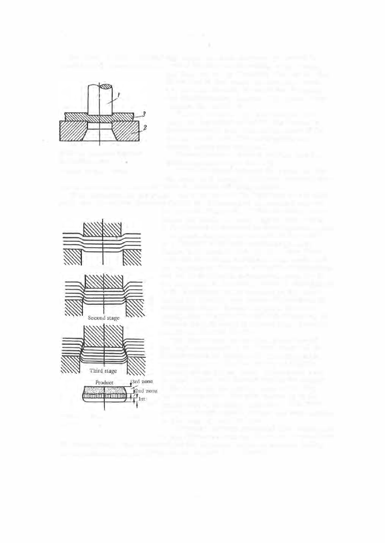
S e c o n d s t a g e . During this stage, in which stres s es go beyond the
elas tic limit, there occurs a further bending and stretching of the fibe rs ,
FIGURE
1 .
Schematic diagram of
the blanking process
and they are cut by the s harp edges of the die .
A t the end of this s tage , the stres s es reach
the ultimate shearing s trength for the m etal,
and mic rofractures appear. The press force
reaches its m aximum .
T h i r d s t a g e . The beginning of this
s tage is characterized by the app earance of
macrofractures near the cutting edges of the
die and punch, and their propagating at a
definite angle into the m etal .
These fractures develop s wiftly, and the
blank s eparates from the strip .
1- punch; 2-die; 3-stock.
If the clearance between the punch and the
die opening is normal, the punch-side and die
side fractures will meet and form a common sh'earing surface .
I f the clearance i s too small , the di rections o f the fractures d o not coin
cide, and the double s hearing causes the formation of an extended burr on
the p roduct (Figure 3 ) . If the clearance is too
First stage
large , the blank will have rugged edges owing
to the tearing of m aterial in the clearance spac e .
A graph showing the s tres ses i n the m etal
as a function of the ram motion is given in
F igure 4 for a steel strip of up to 4 mm thick
ness and of average hardness . The s ector A B
corresponds to the s tage of elastic deformations
and BC to the plastic deformation s tage (up to
the beginning of shearing). Point C corresponds
to the m aximum s tress imposed on the metal
during the blanking and s ector CD indicates the
rupturing stage . Secto r DE gives the force
which must be applied in order to ove rcom e the
friction when the part is ejected from the strip
and forced through the die .
The three zones o n the late ral s urface of
the part correspond to the three stages of the
blanking p rocess (Figure 2 ). The firs t zone,
corresponding to the first stage, is slightly
rounded off on the die side . The s econd zone
is a cylindrical belt formed during the cutting
of the fibers by the cutting edges of the die,
zone
and corresponds to the ram motion up to the
appearance of shearing fractures . The third
FIGURE 2. Stages of the blanking
zone is a rough conical surface and corresponds
to the stage of metal failure .
process
Clearance between punch a
nd die . Clearance
is the diffe rence between the matching punch and
die dimens ions . The magnitude of the clearance required depends mainly
on the material and the thickness of the part to be blanke d .
5 7