The Use of Computer-Aided Design (CAD) in Clockmaking - part 3
9
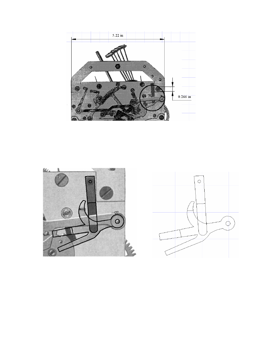
Once the image is scaled, it is a simple process to trace the outline of the lever, leaving
extra material to account for bends and unseen portions. Reference lines, where the
bends are located, will aid in the final shaping of the lever. (Fig. 23)
Once the lever and spring have been traced, they can be printed to scale and used as
templates. (Fig. 24) In the case of the sync lever, the template can be cut out and glued
to a suitable piece of brass and then the brass machined to the trace lines. (Fig. 25)
Fig. 22: An imported image
4
is scaled in the CAD program and
several measurements taken to ensure accuracy. The needed
spring and lever can be clearly seen in the picture (circled).
Fig. 23: The lever and spring can be easily traced,
adding extra material to account for bends.
Fig. 24: The tracings can then be printed to scale
and used as templates for making the spring and
sync lever.