1
The Use of Computer-Aided Design (CAD) in Clockmaking
By David J. LaBounty, CMC FBHI
21
st
century clockmaking uses an interesting mix of antique and modern tools. And,
being constantly tool-poor, clockmakers are always on the lookout for that rare utensil
which will speed up the restoration process. One of the modern tools that fit that
category is the computer. Using a program called computer-aided design or CAD
1
,
clockmakers can design, alter, and manipulate a clock part, working out the bugs long
before the actual piece is made. The uses for CAD in clockmaking are limited only by
one’s imagination!
Drawing an Escapement:
As an exercise in the capabilities of a CAD program, let’s walk through laying out a dead
beat escapement as described by Ward L. Goodrich in his book, The Modern Clock
2
.
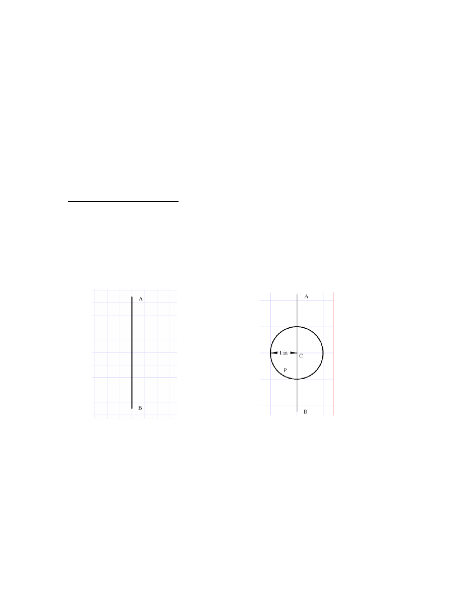
To get started, Goodrich says: “Draw a line, AB,… to serve as a basis for
measurements.” (fig. 1) Then, “…draw from some point C on this line a circle to
represent the diameter of our escape wheel.” (fig. 2)
To follow Goodrich’s example, we will draw the pallets for a 30 tooth escape wheel
spanning 7 ½ teeth at a 90
0
angle. “We now take 90
0
and, dividing it, set off 45
0
each
side of our center line and draw radii, R from the center to the circumference of our
circle; this marks the beginnings of our pallets.” (Fig. 3)
Fig. 1: Step one in drawing
Goodrich’s dead beat escapement.
Line AB.
Fig. 2: Circle P representing the
circumference of a two inch diameter
escape wheel.