Military reference books and manuals (2009-2023, Volume 8) - page 31

Chapter 2
Figure 2-42. AP trip wire-fuzed mines
ANTITANK MINES
2-48. AT mines are much larger than AP mines and may use a variety of fusing including pressure,
magnetic or tilt-rod fuzing. Some of the more modern AT mines have plastic bodies, which make them
hard to detect with a metallic mine detector. The variety of AT mines shown in Figure 2-43 all function by
direct pressure from a tank or vehicle. The mines shown in Figure 2-44, use a tilt-rod fuze that sticks out of
the ground. When the rod is moved or pushed over, the mine detonates.
Figure 2-43. AT pressure-fuzed mines
2-22
FM 4-30.51
13 July 2006

Recognize UXO
Figure 2-44. AT tilt-rod fuzed mines
13 July 2006
FM 4-30.51
2-23
This page intentionally left blank.
Chapter 3
Take Immediate Action
All UXOs found on the battlefield affect maneuver and mission capabilities.
When you find a UXO, you must make some immediate decisions. These
decisions will depend on your current mission, the size and location of the UXO,
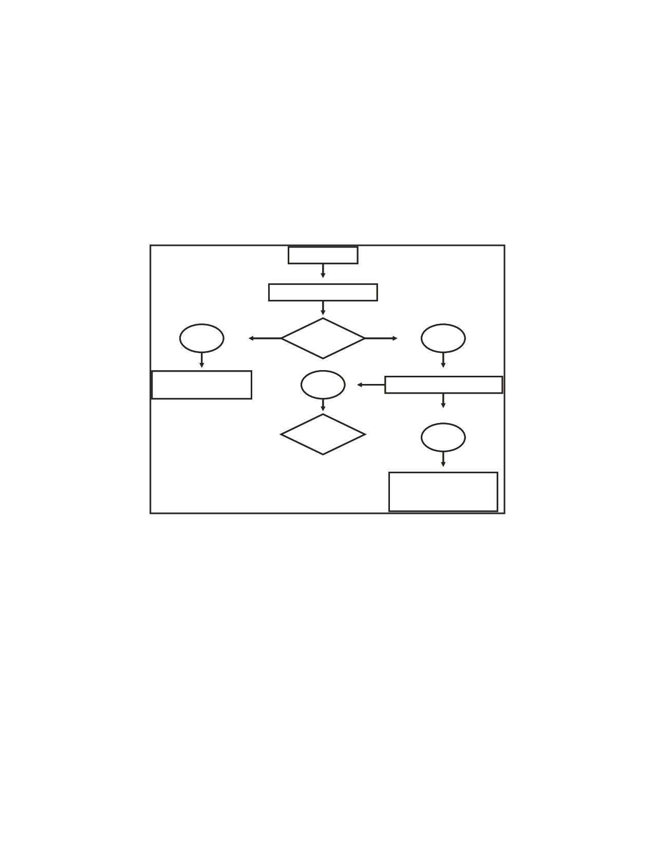
and your unit’s capabilities. Figure 3-1 shows a decision chart to help you decide.
This information is also in GTA 9-12-1, which is available at your local TASC.
DETECT UXO
REPORT IMMEDIATLY
YES
AVOID
NO
MARK IT,
YES
EOD, EOCA AVAILABLE
CONTINUE MISSION
NEUTRALIZE
NO
IMMEDIATE ACTION
EVACUATE, ISOLATE,
AND BARRICADE
Figure 3-1. Decision chart
If at all possible, avoiding/bypassing the UXO hazard is the safest option to take
for personnel and equipment. if the UXO hazard is left from a recent enemy
attack, you must consider protecting your personnel and equipment by extracting
them from the area before another attack is targeted on you. See Chapter 5 for
extraction procedures.
If the mission cannot be accomplished due to the presence of the UXO and the
hazard cannot be avoided/bypassed, protective measures must be taken to reduce
the hazard to personnel and equipment. Regardless of the option you choose, the
location of the UXO must be clearly marked with UXO markers and the hazard
reported to your next higher headquarters. See Chapter 4 for procedures on
reporting a UXO hazard.
13 July 2006
FM 4-30.51
3-1
Chapter 3
PROTECTIVE MEASURES
3-1. There are three methods you can use to protect personnel and equipment. You can evacuate,
isolate, or barricade them.
EVACUATE
3-2. Evacuation of all nonessential personnel and equipment is the best protective measure. The
evacuation distances given in Figure 3-2 provide a reasonable degree of safety for unprotected
personnel and equipment. These distances are based on your estimate of the amount of explosive filler
in the UXO. If protective barricades are used around the UXO, these distances can be reduced.
3-3. The general rule for estimating the amount of explosive in an ordnance item is as follows:
Assume that 50 percent of the total ordnance weight equals the NEW. For example, a 500-pound bomb
would be calculated to have 250 pounds of explosive. According to Figure 3-2, the safe distance for
unprotected personnel is 625 meters. Refer to Appendixes B through E for the NEW of general
ordnance items.
3-4. After all personnel and equipment are evacuated, movement within the area should be kept to
essential operations only. If equipment cannot be evacuated, only mission-essential personnel should
be allowed in the area. The equipment should be protected by barricades and personnel should wear all
protective equipment.
Explosive
Evacuation
Weight (pounds)
Distance (meters)
27 and less
300
30
310
35
330
40
350
45
360
50
375
100
475
150
550
200
600
250
625
300
675
400
725
500
800
Figure 3-2. Evacuation distances
ISOLATE
3-5. Sometimes, for mission-related, operational, or other reasons, you cannot evacuate personnel
and/or equipment or you cannot leave a particular area. When this happens, you must isolate either
your assets (personnel, equipment, and operations) from the UXO or isolate the UXO from your assets.
See Figure 3-6, 3-7, and 3-8.
BARRICADE
3-6. If your unit is stationary, evacuate all nonessential personnel and equipment out of the hazard
area. Equipment that cannot be moved must be protected with barricades. Personnel who cannot be
evacuated from the area must also be protected from the hazard. You can do this by reinforcing the
fighting positions on the side facing the hazard and by adding overhead cover.
3-7. A barricade is an artificial barrier that provides limited protection by channeling the blast and
fragmentation from the threatened area. Barricades may also be used to lessen the effect of the blast
3-2
FM 4-30.51
13 July 2006

Take Immediate Action
and to reduce the size of the evacuation area. When determining if barricades are needed, you must
estimate the probable damage that would result if the UXO were to explode. Building artificial
barricades is very time consuming and requires a large number of sandbags. Depending on the size of
the UXO, barricades can be built around the UXO to protect the entire area, or they can be built next to
the equipment or areas that cannot be evacuated.
3-8. Use the following general guidelines when building barricades:
z
Calculate the total destructive power of the UXO hazard. Multiply the number of items by
their NEW.
z
Determine which assets cannot be moved or evacuated from the area safely.
z
For those assets that cannot be moved or evacuated, decide on the type of barricade(s) you
will need to protect your assets. Sandbags, or other dirt or water filled barriers can be used.
Concrete barriers are not preferred near the ordnance item as they tend to produce more
fragments.
z
Determine how many personnel are available to help build barricades. Use the absolute
fewest personnel. Determine what equipment you can use. If earth-moving equipment is
available, you can build earth barriers in place of sandbag barricades.
z
Calculate the number of sandbags you will need or that are already available to build
barricades. Personnel evacuated from the UXO area can fill sandbags and transport them to
the barricade site.
z
Make sure that all personnel actually building barricades are wearing all available safety
equipment. This safety equipment includes a kevlar helmet, a flak vest, and hearing
protection.
PLACEMENT AND SIZE OF BARRICADES
3-9. The barricade should be built no closer to the UXO than the height for the barricade plus 3 feet.
Further guidance on the height for barricades is provided later in this section. For example, the
barricade shown in Figure 3-3 is 5 feet tall. By adding an additional 3 feet, the barricade is built no
closer than 8 feet to the UXO. Build the barricade between the building and/or the equipment to be
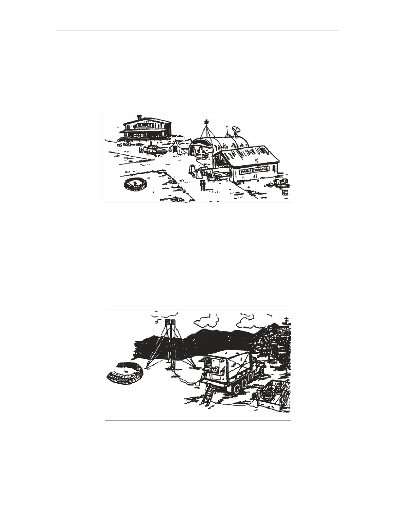
protected and the UXO. By positioning the barricade in this location, personnel who are in or around
the building or who are using the equipment will be afforded the greatest protection from the blast and
flying fragments. See Figure 3-4. Refer to para 3-11 thru 3-13 for the appropriate height of a barricade.
Figure 3-3. Placement distance for barricade
13 July 2006
FM 4-30.51
3-3

Chapter 3
Figure 3-4. Placement of wall barricade
3-10. When building a barricade, the sandbags must be interlocked for stability. See Figure 3-5.
Sandbags that are not interlocked will reduce protection and make the barricade unstable.
Figure 3-5. Interlocking sandbags
3-11. Small UXO. For small UXOs such as missiles and rockets less than 70 millimeters in diameter,
for projectiles less than 75 millimeters in diameter, and for submunitions and grenades, a double wall
thickness of sandbags should surround the area of the UXO. The sandbags must be stacked to a height
of at least 3 feet and should be thick enough to protect personnel and equipment from the blast and
fragmentation. This type of barricade may be semicircular or circular. Types of barricades are
discussed later in this section.
3-12. Medium UXO. For medium-sized UXOs such as missiles, rockets, and projectiles up to 200
millimeters in diameter, and for large sized placed munitions on the surface, a four- or five-wall
thickness of sandbags should surround the area. The sandbags must be stacked to a height of at least 5
feet in order to protect assets. This type of barricade is usually semicircular.
3-13. Large UXO. Large UXOs such as projectiles, missiles, and general-purpose bombs are too large
for effective barricades to be built around the ordnance item. In these cases, equipment and personnel
activity areas would need to be barricaded. A wall barricade between the affected area and the UXO
hazard provides the best and easiest protection. Jersey or Texas concrete barriers can be used to protect
assets in this situation since the barrier is further away from the ordnance site.
3-4
FM 4-30.51
13 July 2006
Take Immediate Action
BARRICADE TYPES
3-14. The three types of barricades are circular, semicircular, and wall. The type barricade that you use
will depend on the UXO hazard and the area that requires protection.
z
Circular. A circular barricade is the best choice for small UXO hazards, because it provides
complete protection for personnel and equipment. A circular barricade that is 8 feet in
diameter, 3 feet tall, and 3 sandbags thick would require approximately 400 sandbags. The
barricade shown in Figure 3-6 will force the blast upwards and contain the majority of the
fragments.
Figure 3-6. Complete circular placement of barricade
z
Semicircular. A semicircular barricade is used for small- and medium-sized UXO hazards.
It will channel the blast and fragmentation through the open side and away from the
protected area. See Figure 3-7.
z
Wall. The wall barricade protects specific equipment or personnel areas. It is used when the
UXO hazard is too large to contain by using a circular or semicircular barricade. The
number of wall barricades you need will depend on how much equipment or how many
personnel you must protect. A wall barricade that is 12 feet long, 6 feet high, and 3
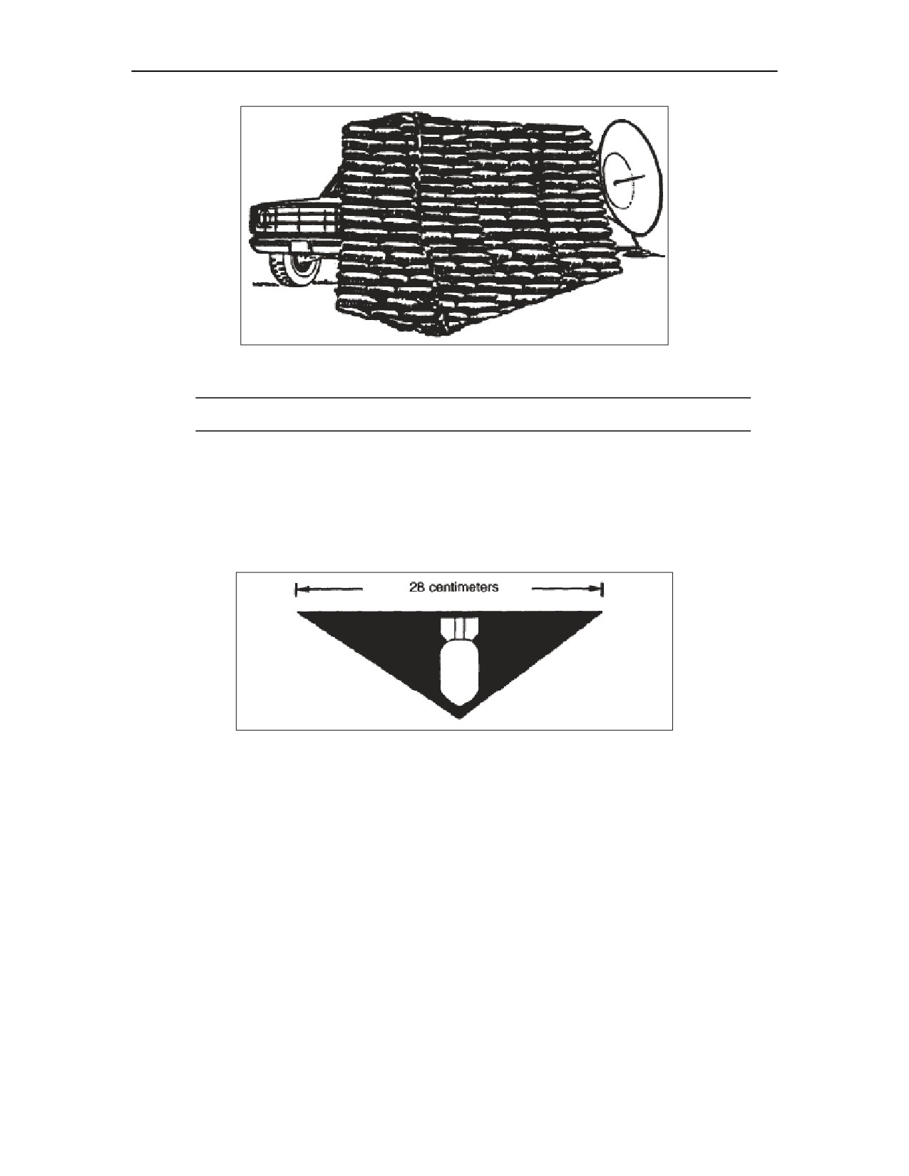
sandbags thick would require 700 sandbags. As shown in Figure 3-8, the barricade should
extend beyond and be at least as tall as the equipment or personnel areas to be protected.
Equipment that is barricaded must still be usable. For example, the radar shown in Figure 3-
8 must be left exposed in order to function.
Figure 3-7. Semicircular placement of barricade
13 July 2006
FM 4-30.51
3-5
Chapter 3
Figure 3-8. Wall barricade placement
This item implements STANAG 2002, Edition 7.
MARK UXO
3-15. Marking a UXO hazard is just as important as marking other hazard areas such as CBRNE areas,
minefield, and booby-trapped areas. All of these hazards are marked by using triangular signs, if
readily available, that by their backg3round color indicate the danger involved. The standard UXO
marker is shown in Figure 3-9. The backg3round is red with a white bomb inset. It has the same
dimensions as the other markers.
Figure 3-9. Standard UXO marker
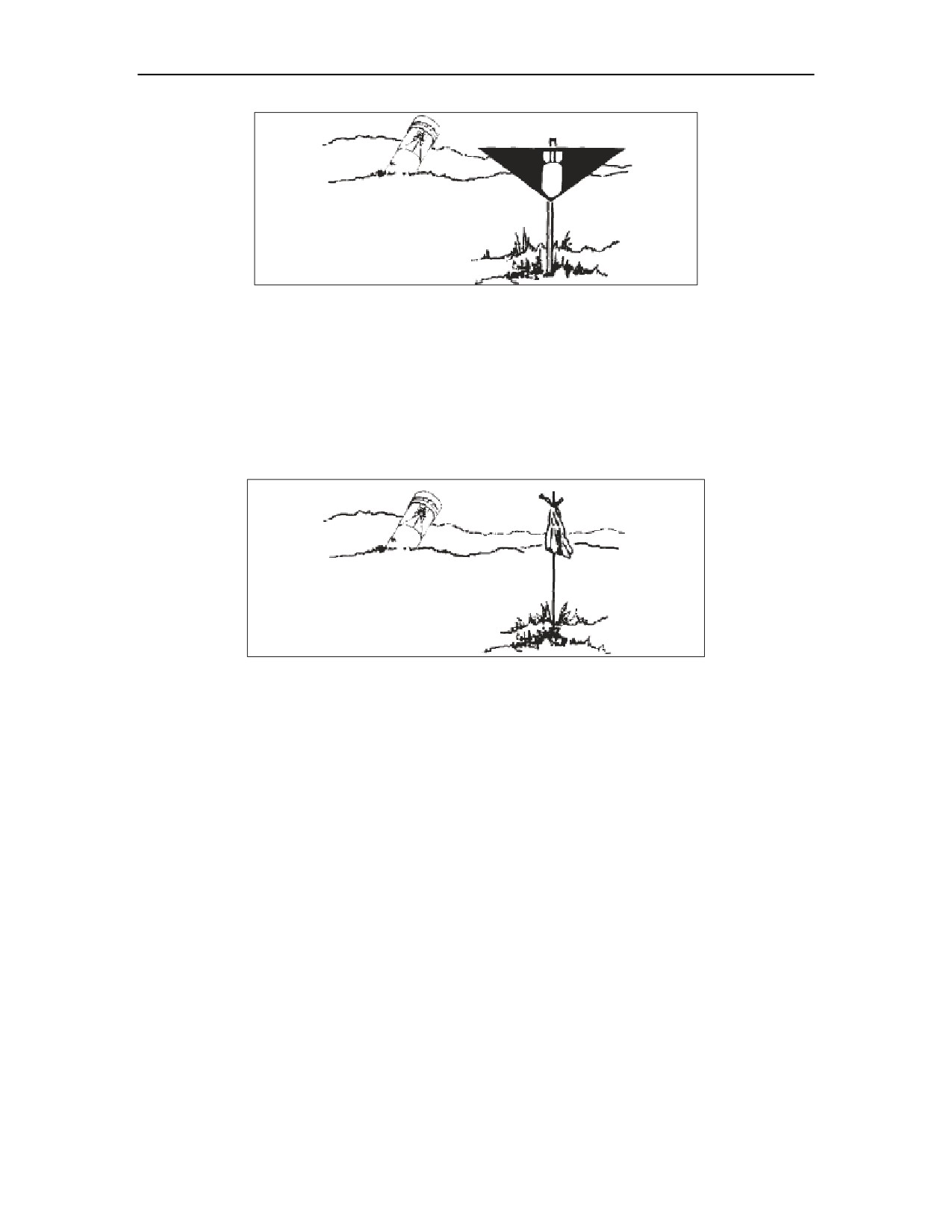
3-16. The UXO marker is placed above ground at waist level (about 3 feet) with the bomb pointing
down as shown in Figure 3-10. The marker should be placed no closer to the hazard than the point
where you first recognized the UXO hazard. The marker should be attached to a stake (Figure 3-10), a
tree, or other suitable holder. Just be sure that the marker is clearly visible.
3-17. You should also mark all logical approach routes to the area. If the hazard is near a road, as a
minimum, put a marker on each side of the road approaching the UXO. If there is a large concentration
of UXO hazards such as submunitions, mark the area as you would a scatterable minefield, with
markers placed about every
15 meters around the area. Refer to FM
3-34.210 for additional
information on marking minefields.
3-6
FM 4-30.51
13 July 2006
Take Immediate Action
Figure 3-10. Marking a UXO with standard marker
3-18. As a general rule, the UXO hazard itself must be easily seen from any of the markers. This helps
to keep others away from the hazard. It also helps the EOD team to find the hazard.
3-19. If standard UXO markers are not available, you may use other suitable materials (such as
engineer tape or colored ribbons). Try using the same color ribbon to avoid confusion. When using
other materials, the same principles used for the standard markers apply for placement of the makeshift
markers. That is, they should be placed about 3 feet off the ground and easily seen from all approach
routes. See Figure 3-11.
Figure 3-11. Marking UXO with alternate type of material
13 July 2006
FM 4-30.51
3-7
This page intentionally left blank.
Chapter 4
Report the UXO Hazard
As discussed in Chapter 1, UXO hazards on the battlefield have an enormous effect
on command and control decisions for battle planning. The location of these hazards
is vital to the command and control elements when projecting movement and support
of combat units. UXO hazards also have a direct impact on the combat capabilities of
any element that encounters them. To assist commanders, an effective UXO reporting
system must be in place and maintained to allow commanders to concentrate EOD
assets according to priorities and battle plans.
EXPLOSIVE HAZARDS SPOT REPORT
4-1. The EH spot report (formally known as the UXO spot report) is a detailed, swift, reporting system
that makes clear where the UXO hazard areas are, what their priorities are, and which units are affected by
them. The report is used to request help in handling a UXO hazard that is beyond a unit’s ability to handle
and that affects the unit’s mission. This report helps the commander set priorities based on the battlefield
situation. If tactically feasible add a digital photo to the Spot Report. Digital photos can greatly assist EOD
personnel in identifying UXO and therefore providing any subsequent recommendations to the reporting
unit.
4-2. The EH spot report is the first-echelon report that is sent when a UXO is encountered. Information
about this report is also found in GTA 9-12-1 and in the supplemental information section of the signal
operating instructions (SOI), where it is just behind the request for medical evacuation (MEDEVAC).
4-3. The EH spot report lets personnel on the battlefield report found UXOs, improvised explosive
devices (IEDs), and captured enemy ammunition (CEA) through the appropriate channels. It provides a
brief description, location, and recommended priority to assist in determining response categories. The
report consists of nine lines, and is sent by the reporting unit using the fastest means available.
z
Line 1. Date-Time Group. The DTG that the item was discovered.
z
Line 2. Reporting Unit and Location. The unit identification code (UIC) of the reporting
activity unit and the location of the explosive hazard in an 8-digit grid coordinate.
z
Line 3. Contact Method. Provide the radio frequency, the call sign, the point of contact, and the
telephone number.
z
Line 4. Type of Munition. Note the size, quantity, type of ordnance (dropped, projected, placed,
or thrown), and subgroup, if available. Note if antihandling devices were used. Indicate the
emplacement method and type of initiation device.
z
Line 5. CBRN Contamination. - If present, be as specific as possible. (Chemical agent monitor
(CAM) detected G Agent at 3 bars; Soldiers are experiencing symptoms of Nerve agent etc….)
z
Line 6.
Resources Threatened. Report any equipment, facilities, or other assets that are
threatened.
z
Line 7.
Impact on Mission. Provide a short description of your current tactical situation and
how the presence of the explosive hazard affects your status (for example, delayed, diverted,
cancelled).
z
Line 8.
Protective Measures Taken. - Describe measures taken to protect personnel and
equipment. (Personnel evacuated to 300M, marked, Sandbag barrier constructed etc…)
z
Line 9.
Recommended Priority (Immediate, Direct, Minor, No Threat). Recommend a
priority for response by EOD. Ensure that the priority requested corresponds with the tactical
situation you described on line 7 of the report (Impact on Mission). These priorities refer only to
13 July 2006
FM 4-30.51
4-1
Chapter 4
the explosive hazard’s impact on your current mission. A priority of MINOR or NO THREAT
does not mean that the explosive hazard is not dangerous. (See PRIORITIES below)
Line 1.
DTG
131200ZAUG04
Line 2.
Reporting activity
2/505 PIR, BS13221433.
Line 3.
Contact method
F400, Shockwave3 SGT Turner
Line 4.
Type of ordnance
82MM Mortar 1 EA
Yes, the Soldiers have blisters. M8 paper confirms the
Line 5.
CBRN contamination
presence of a chemical agent.
Line 6.
Resources threatened
Personnel, Mortar Emplacement
Line 7.
Impact on mission
Counter fire operations stopped.
Line 8.
Protective measures
Personnel evacuated to 300M, Sandbag barrier constructed
Line 9.
Recommended priority
Immediate
Figure 4-1. Explosive Hazard Spot Report
PRIORITY BASIS
4-4. Priorities are defined by the commanders’ guidance. The EOD commander coordinates EOD incident
categories and priorities with the commanders staff based on the supported commanders priorities. The four
priorities established for EOD support are—
z
Immediate. This priority stops the unit’s maneuver and mission capability, or threatens critical
assets vital to the mission.
z
Direct. This priority restricts the unit’s maneuver and mission capability, or threatens critical
assets important to the mission.
z
Minor. This priority reduces the unit’s maneuver and mission capability, or threatens non-critical
assets of value.
z
No threat. This priority has little or no effect on unit capabilities or assets.
PRIORITIZING THE SPOT REPORT
4-5. The UXO spot report is forwarded through your chain of command. Each commander in the chain
who receives/reviews the report may change the priority to reflect the current tactical situation or projected
battle plans. It is the responsibility of each commander in the chain to ensure that UXO spot reports are
forwarded through command channels and that the proper priority is set for each report.
4-6. If a higher-level commander in the chain changes a priority, all subordinate commanders, especially
the commander of the reporting unit, must be told. Commanders must keep the following in mind: even
though they may lower a priority, the reporting unit must be able to continue its mission until help comes.
In addition to the priority status, all commanders need to be kept informed of the status of each UXO
hazard in their area.
4-7. The final priority is determined by the reporting unit’s higher headquarters that is supported by EOD.
Based on mission, enemy, terrain and weather, troops and support available-time available (METT-T),
EOD are dispatched to respond to the hazard.
4-2
FM 4-30.51
13 July 2006
Chapter 5
Self-Extraction from UXO Hazards
The use of submunitions and scatterable mines on the modern battlefield will
have a direct impact on mobility, survivability, and logistical support
requirements. All units must be able to maintain their mobility despite these
hazards. Our forces must be able to self-extract from submunition and scatterable
mine threats in order to survive.
EOD units are responsible for the elimination of these threats from the
battlefield, while engineer elements provide breaching and mine-clearing support
for these threats. These elements may not be readily available to all units that
receive submunition or scatterable mine attacks from the enemy. Any unit that
cannot self-extract will risk being destroyed in place by follow-on attacks.
DETECTION
5-1. Detection is the first step in extraction. Submunitions and scatterable mines are very small in
size and are difficult to detect in optimum circumstances. In some terrain, such as dense foliage, tall
grass, or uneven ground, many of them will go undetected. During periods of limited visibility or at
night, detection is almost impossible. Combat vehicle personnel traveling cross-country in a buttoned-
up vehicle will be at a great disadvantage, because they will not be able to see them or to avoid them.
5-2. The unit detecting a submunitions area or scatterable minefield is required to report it, mark it,
and, if so directed, breach through it. All areas will remain marked until they are cleared.
IMMEDIATE ACTIONS
5-3. When an operating area becomes contaminated with submunitions or scatterable mines, a certain
amount of confusion is understandable. Therefore, a recognized and rehearsed system of alerting
personnel to the danger and orders on how to evacuate the area are essential. Alerting systems may
include loudspeakers, radios, or runners. A combination of these systems may be the most effective.
5-4. The unit field SOP should include procedures for evacuating personnel from an area and
reestablishing operations at another location. An established and trained evacuation plan will reduce
personnel and vehicle losses. The plan must be flexible so it can be adapted to fit the different
scenarios and environments that might be encountered.
5-5. When setting up operational bases or work sites, the UXO threat must be considered. Roads are
critical for evacuation. Hard surfaced roads are the best evacuation routes and are also the easiest to
clear. The evacuation plan should include procedures for unit elements to reconnoiter and mark clear
paths or to link paths from other unit positions to their position and to the nearest hard surfaced road.
5-6. A unit that has been directly fired on must presume that more fires are coming. The unit must be
able to self-extract from the area in order to resume operations or be able to protect assets in order to
continue the assigned mission. The extraction procedure resembles an in-stride breach as outlined in
FM 3-34.210 and FM 90-13-1, or in MCWP 3-17.3 for the Marine Corps. Units that are conducting
movement operations can use route clearance procedures to force a cleared lane through the area only
as a last resort. Most units are not equipped to deal with this situation and the results could be as
devastating as the attack itself.
13 July 2006
FM 4-30.51
5-1
Chapter 5
5-7. Combat units that have the assets to conduct an in-stride breach can do so and reduce the hazard
for follow-on forces and continue in the original direction of the march. CS and combat service support
(CSS) units must rely on their OPORD to designate alternate support areas. These units must employ
their organic assets to reconnoiter and create cleared lanes in the direction of the alternate support
location. Not all equipment may be retrievable. The emphasis should be placed on relocating personnel
and operational equipment as quickly as possible.
SITUATIONAL ASSESSMENT
5-8. After taking immediate actions to alert personnel, locate the submunitions or scatterable mines,
and provide protection for personnel and equipment, the following operational situation and tactical
factors should be assessed:
z
Effect of the delay on the mission.
z
Threat from direct and indirect fire. The risk of casualties from direct or indirect fire may be
greater than that from the submunitions or scatterable mines.
z
Type of terrain. The terrain determines the effectiveness of submunitions or scatterable
mines, their visibility, and, consequently, their ability to be detected, avoided, or
neutralized.
z
Alternate routes or positions available.
z
Degree of protection available.
z
Availability of specialized support, such as EOD or engineer teams and equipment.
5-9. After assessing the situation, three main options are available, as follows:
z
Accept the risk of casualties and continue with the assigned mission.
z
Employ tactical breaching procedures and extract to alternate routes or positions.
z
Employ preplanned alternate tactical plans according to the current OPORD.
BREACHING TECHNIQUES
5-10. Hazardous areas must be bypassed if at all possible. When bypassing is not feasible, you must
try to neutralize the submunitions and scatterable mines that prevent movement. There is no single
device or technique that will neutralize every submunition or scatterable mine in every situation. The
differences in fuzing, self-neutralization, terrain, and unit mission mean that multiple techniques must
be considered.
5-11. When employing breaching techniques, take all protective measures possible to protect
personnel and equipment. Personnel who are not directly involved should be under cover, away from
the area. Personnel who are directly involved must make use of all available cover. These approved
extraction techniques are listed from least to most hazardous and should be considered for execution in
this order:
z
Perform area reconnaissance, and mark a cleared route.
z
Use engineer equipment to remove or destroy items.
z
Destroy items using explosive charges.
z
Contain the item by building protective works.
z
Destroy items using direct-fire weapons.
DANGER
Employing breaching techniques on ordnance other than
submunitions or scatterable mines is not recommended. The
amount of explosives involved would create more of a hazard
to your operations than the UXO itself.
5-2
FM 4-30.51
13 July 2006
Self-Extraction from UXO Hazards
WARNING
Prior to employing breaching techniques, make sure that
none of the items are filled with chemical, radiological, or
biological agents.
UXO CONSIDERATION FOR SELF EVACUATION
5-12. After indirect fire attack immediate action drills for self extraction must include a plan to
mitigate the hazards of UXO.
5-13. If you enter a minefield or UXO saturated area, evacuate by the same route you entered, marking
the route if situation permits.
ENGINEER EQUIPMENT (HEAVY-FORCE BREACHING)
5-14. Using engineer equipment is the preferred method of breaching small submunitions and
scatterable mines. This procedure allows for the quickest clearance of an evacuation route. Suitable
equipment includes a bulldozer
(with mine clearance armor protection if possible), deployable
universal combat earthmover (DEUCE), combat vehicle mounted with a mine clearing blade or roller,
or an armored combat earthmover (ACE). If an unarmored vehicle is used (such as a bulldozer or a
grader), the operator’s cab must be protected by sandbags.
5-15. Four major disadvantages to heavy-force breaching are as follows:
z
Operators may be killed or injured.
z
Equipment may be damaged. If either happens, extraction through the area will be
hampered.
z
Equipment may only partially clear the area, requiring further clearance procedures.
z
Equipment may bury some submunitions or scatterable mines, which would keep them from
being detected while using the evacuation route.
EXPLOSIVE CHARGES
MINE-CLEARING LINE CHARGE
5-16. The mine-clearing line charger (MICLIC) is a rocket-propelled explosive line charge used to
reduce minefield containing single impulse, pressure-activated AT mines and mechanically activated
AP mines. It has limited effectiveness against magnetically activated mines, including scatterable
mines and those containing multiple-impulse or delay-time fuzes.
5-17. The MICLIC will explosively clear a path through an area. Several MICLICS may be required in
the same area to ensure that a wide enough path is cleared.
5-18. Three major disadvantages to using MICLICs are as follows:
z
The explosive charges may not be close enough to the submunition or scatterable mine to
cause destruction. This can result in “kick outs” where submunitions or scatterable mines
can be thrown away from the detonation, possibly towards your position.
z
Further reconnaissance of the area is required prior to using the route for evacuation in order
to detect those submunitions or scatterable mines that are still in place after using MICLIC.
z
MICLIC cannot be used if high order detonation or explosives in the area is not acceptable.
13 July 2006
FM 4-30.51
5-3
Chapter 5
PLACED EXPLOSIVE CHARGE
5-19. This is the most effective way to clear an evacuation route. If at all possible, the explosive
charges should be remotely placed to the side of the UXO as close as possible without touching it. If it
can not be done remotely hand emplacement of the charge is the most hazardous and time consuming
procedure. The explosive charge should be large enough to consume the item and placed to the side of
the UXO that is closest to the unit’s position. This will direct most of the fragmentation away from the
unit. Enough time delay should be used to allow personnel to return to a safe area prior to the
detonation.
5-20. Four major disadvantages to using placed charges are as follows:
z
They are very labor intensive to use and expose personnel to a greater risk, especially if the
submunitions use magnetic, delay, or trip-wire fuzing.
z
Their use is very slow and time consuming, because all items must be detected, marked, and
destroyed individually.
z
They cannot be used if detonation of the submunitions or scatterable mines will cause
unacceptable damage to the operational area and/or equipment.
z
They should not be used in heavy concentrations of submunitions or scatterable mines. The
detonations will cause “kick outs.”
CONTAINMENT
5-21. For containment see Chapter 3.
z
There is one major disadvantage to containment. Building barricades is time consuming and
thereby exposes a large number of personnel to the UXO.
UXO DIRECT-FIRE WEAPONS
5-22. This is the least preferred method of clearance. Submunitions and scatterable mines can be
destroyed or disabled by the use of direct-fire service weapons. The goal of this procedure is to
produce a disabling reaction that rapidly reduces or eliminates the designed fuze functioning of the
submunition or scatterable mine. Service weapons such as the 5.56 millimeter, the 7.62 millimeter, the
.50 caliber, and the 25 millimeter will most likely produce the desired effect. The person firing the
service weapon should approach the UXO only close enough to be able to fire accurately. However,
this person should never be closer than 300 meters to the item. When performing the direct-fire
procedure, the aiming point is center mass. Single shots should be fired until the item is hit. On some
larger items, multiple hits may be required to be sure that the submunition or scatterable mine has been
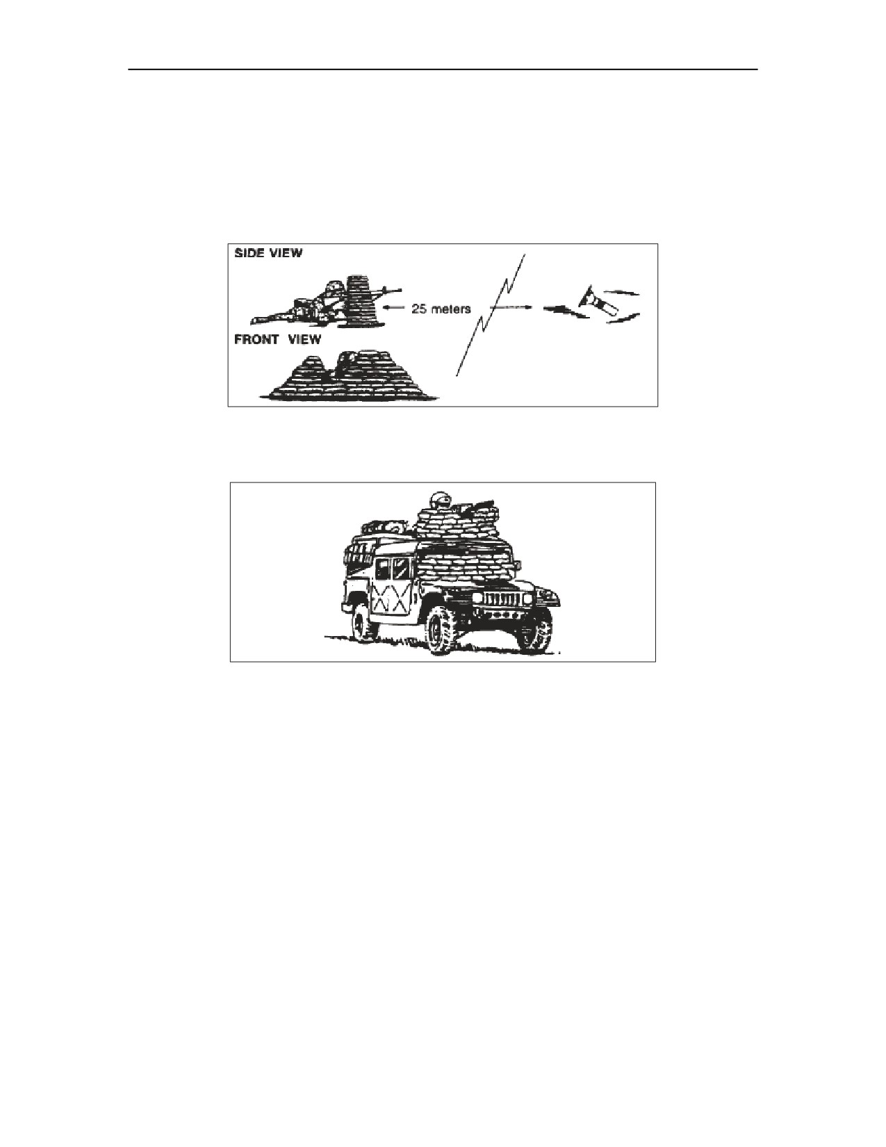
disabled. Frontal protection is required for mounted and dismounted personnel. Figure 5-1 shows the
dismounted procedure, while Figure 5-2, shows the light-vehicle mounted procedure with sandbags
being used for frontal protection. If several persons are being used to clear a large area, ensure that
each person is protected sufficiently from all areas. No one person should be closer than 300 meters to
any item being engaged.
5-23. This technique has many variables and must only be performed by personnel with the
appropriate training. Certain smaller caliber weapons will have little to no effect on some ordnance
items and leave it in a more hazardous state. If personnel are trained in UXO direct-fire techniques this
by no means implies that they are qualified to use direct-fire techniques for IEDs or other specific
ordnance items.
5-24. Five major disadvantages to direct-fire destruction are as follows:
z
It is very slow and time consuming. Each item must be individually located, and each
person can only engage one target at a time.
z
Some submunitions are too small to engage effectively with direct-fire weapons from a
distance of
25 meters. The terrain has a major affect on this procedure. Because
submunitions and scatterable mines are so small, it does not take very much vegetation or
loose dirt to hide them.
5-4
FM 4-30.51
13 July 2006
Self-Extraction from UXO Hazards
z
This technique is applicable only to high explosive filled munitions and can be used only
when the possibility of high order detonation of the targeted UXO is tolerable. High order
detonation can cause sympathetic detonation of other munitions.
z
The detonation of the submunition or scatterable mine can result in “kick outs” where
submunitions or scatterable mines can be thrown away from the detonation, possibly
towards your position.
z
If the ordnance item is damaged and not destroyed it may be more sensitive and the
disrupted components may be more hazardous.
Figure 5-1. Dismounted direct-fire procedure
Figure 5-2. Light-vehicle mounted direct-fire procedure
13 July 2006
FM 4-30.51
5-5
This page intentionally left blank.
Chapter 6
UXO Response to the Battlefield
EOD units are responsible for identifying, rendering safe, recovering, evaluating,
disposal, threat mitigation, and reporting (EOD and Intelligence) of unexploded US
and foreign explosive ordnance. This includes chemical, biological, and radiological
weapons which have been fired, dropped, or placed in such a manner so as to
constitute a hazard to installations, personnel, materiel or operations. The mission of
EOD is to eliminate or reduce hazards and to protect the commander’s combat power.
CAPABILITIES
z
Render Safe UXO hazards.
z
Identify UXO hazards.
z
Destroy UXO hazards.
z
Move UXOs to Safe Holding or Disposal areas within the limitations of their organic
transportation Assets.
z
Perform Technical Intelligence on new or first seen ordnance items.
z
Perform post-blast forensic analysis.
z
Perform specialized demolition techniques and procedures.
SUPPORT REQUIREMENTS
z
Security forces.
z
Medical Support.
z
Fire Fighting Support.
z
Supported unit provides and builds protective measures.
OTHER SUPPORTING ORGANIZATIONS
z
Combat Engineer Companies.
z
Military Intelligence Company/Teams.
z
Army Explosive Ordnance Clearance Agents (EOCA).
ARMY EXPLOSIVE ORDNANCE CLEARANCE AGENT (EOCA)
6-1. The design of the Army EOCA is to enhance the engineer’s ability to assure mobility and provide
maneuver units with a limited alternative capability to counter unexploded ordnance. Army EOCAs are
combat engineers who have attended and graduated from the Army EOCA course. The “Army Explosive
Ordnance Clearance Agent (EOCA) Identification Guide” provides more information on Army EOCA. To
perform in an Army EOCA capacity, these Soldiers must pass the Army EOCA course at the Ordnance
Munitions and Electronic Maintenance School (OMEMS), Redstone Arsenal, Alabama.
6-2. Army EOCA personnel are trained to perform limited battlefield disposal of UXOs as outlined in
Army EOCA Identification Guide and JOA UXO supplemental list. If the UXO is out of the scope of
operations for the Army EOCA, EOD Soldiers must respond. Army EOCA Soldiers can assist EOD Soldiers
in disposing of other EH as requested. Properly trained and certified Army EOCA Soldiers capabilities
include:
z
UXO reconnaissance. Army EOCA personnel are trained to perform detailed reconnaissance of
suspected UXO.
13 July 2006
FM 4-30.51
6-1
Chapter 6
z
UXO identification. Army EOCA can perform limited identification of items listed in EOCA
Identification Guide and JOA UXO supplemental list. Items that the Army EOCA cannot
positively identify must be reported to EOD personnel.
z
UXO area marking. Army EOCA personnel mark UXO area in accordance with the standard
UXO marking system.
z
Protective works. Army EOCA can provide blast and fragmentation danger area of identified
UXOs. Army EOCA may provide estimated blast and fragmentation danger area for items
similar to but not included in Army EOCA Identification Guide and JOA UXO supplemental
list. Army EOCA will advise the on scene commander on recommended personnel and
equipment protection measures. When the commander determines that certain personnel or
equipment can not be removed from the hazard area, protective works must be established to
protect those personnel and assets from the effects of the UXO. Army EOCA will recommend
and supervise the appropriate protective works to be completed.
z
UXO Disposal. Army EOCA personnel are authorized to destroy by detonation individual UXOs
identified in Army EOCA Identification Guide and JOA UXO supplemental list.
ARMY EOCA LIMITATIONS
z
No reconnaissance or handling of IEDs or Large Vehicle Improvised Explosive Devices
incidents.
z
Can only perform CEA operations under the direct supervision of EOD personnel.
z
Cannot move, combine, and/or destroy multiple UXOs.
6-3. Army EOCA Soldiers are not to be used for explosive hazard response calls.
6-4. The US Marine Corps does not have Explosive Ordnance Clearance Agent and relies on EOD to clear
UXOs and IEDs, unless passing through an area containing UXO or IEDs is deemed a mobility requirement by
the commander, in which case engineers will create a “breach” through the affected area much the same as they
would breach through an explosive obstacle on the battlefield.
Emergency destruction of CEA that is 90mm and smaller is taught to Marine Corps engineer officers
and NCOs at Marine Corps Engineer School. Positive identification of all ordnance items to be destroyed is
required and a necessity must exist to justify the destruction of CEA by engineers; for example, in order to
prevent ordnance from falling into enemy hands. Key portions of the course taught at Marine Corps Engineer
School (MCES) pertaining to destruction of CEA are identification of ordnance items, calculating the net
explosive weight of the CEA plus the charge used to destroy it, calculating the minimum safe distance needed
to destroy CEA, and the use of a decision process when assessing a CEA situation.
As new counter-IED technologies become available, for example, the Buffalo and MARCbot robot,
MCES plans to include the TTPs required for successful employment in its programs of instruction.
6-2
FM 4-30.51
13 July 2006
Appendix A
Ammunition Color Codes
The color codes and markings in this appendix are for informational purposes only.
They are provided to help you identify the different types of UXO. Keep in mind that
each country that manufactures munitions has devised its own color codes.
Remember do not approach a UXO any closer than necessary to make an immediate
identification. Remember also, that you are not responsible for determining UXO
fillers.
The ammunition color codes in Tables A-1, A-2, and A-3 are used by the US and
NATO. The ammunition color codes in Tables A-4 and A-5 are used by the former
Soviet Union. The markings used on Soviet chemical munitions are in Table A-6.
13 July 2006
FM 4-30.51
A-1

Appendix A
Table A-1. US and NATO color codes
A-2
FM 4-30.51
13 July 2006

Ammunition Color Codes
13 July 2006
FM 4-30.51
A-3

Appendix A
A-4
FM 4-30.51
13 July 2006

Ammunition Color Codes
Table A-2. Former Soviet Union color codes for bombs
Nose Band
Body Band
Type
Green
Blue
Fragmentation
Green
Blue and Green
Fragmentation and Chemical
Orange
Semi-armor Piercing
Blue
Armor Piercing
Red
Blue
Incendiary
Red
Incendiary Dispenser
Red
Green
Persistent Chemical
Green
Green
Non-persistent Chemical
White
White
Parachute Flare
Blue
Black
Rocket Assisted
Red
White
Practice
Table A-3. Former Soviet Union color codes for projectiles
Color Codes (Bands)
Type
Red
Incendiary
Blue
Concrete Piercing
Black
Smoke
White
Illumination
Yellow
Ball Shrapnel
Khaki
Bar Shrapnel
One Green Band
Non-persistent Agent
Two Green Bands
Persistent Agent
Table A-4. Former Soviet Union markings for chemical munitions
Marking
Chemical Filler
P-4
White Phosphorus
P-5
Mustard Agent
PC
Lewisite Agent
P-10
Phosgene Agent
P-15
Adamsite (DM)
TP
Thermite
13 July 2006
FM 4-30.51
A-5
This page intentionally left blank.

Appendix B
Dropped Ordnance Identification and Net Explosive
Weight (NEW)
BOMBS
Figure B-1. Bomb, general purpose, 2,000 pound
NEW: 1,000 pounds
Figure B-2. Bomb, general purpose 500 kilogram
NEW: 550 pounds
13 July 2006
FM 4-30.51
B-1

Appendix B
Figure B-3. Bomb general purpose 250 pound
NEW: 125 pounds
Figure B-4. Bomb general purpose 100 kilogram
NEW: 110 pounds
NOTE: This dispenser is loaded with BLU-97/B submunitions. However, it can be loaded
with a variety of submunitions.
Figure B-5. Submunition dispenser CBU-87/B
NEW: Not Applicable
B-2
FM 4-30.51
13 July 2006

Figure B-6. AP/AMAT submunitions
NEW: less than 0.5 pounds per item
Figure B-7. AP/AMAT submunitions (conventional)
NEW: less than 7 pounds per item
13 July 2006
FM 4-30.51
B-3

Appendix B
Figure B-8. AMAT/AT submunitions (conventional)
NEW: Less than 2 pounds per item
B-4
FM 4-30.51
13 July 2006

Figure B-9. Soviet style AMAT/AT submunitions (conventional)
NEW: less than 2 pounds per item
Figure B-10. Area denial submunitions: ADAM (left), RAAMS (middle) and BLU-54/B (right)
NEW: RAAMS 2 pounds, ADM and BLU-54/B less than 0.5 pounds
13 July 2006
FM 4-30.51
B-5

Appendix B
Figure B-11. Area denial submunitions: M74 (left, BLU-91/B “Gator” (right) and AT-2 (rear)
NEW: 2 pounds per item
B-6
FM 4-30.51
13 July 2006

Projected Ordnance Identification and Net Explosive Weight (NEW)
Appendix C
Projected Ordnance Identification and Net Explosive
Weight (NEW)
PROJECTILES
Figure C-1. Spin stabilized projectiles, 105 millimeter and smaller
NEW: less than 8 pounds per item
13 July 2006
FM 4-30.51
C-1
Appendix C
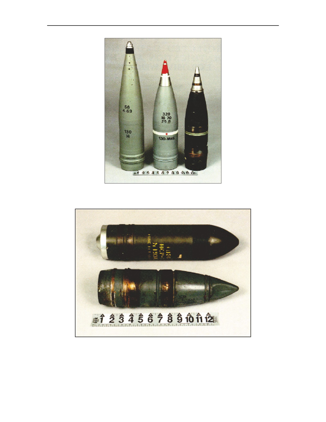
Figure C-2. Spin stabilized projectiles 130 millimeter
NEW: less than 20 pounds per item
Figure C-3. Spin stabilized projectiles 105 millimeter high explosive plastic (HEP) (top) and
100 millimeter armor piercing (AP) (bottom)
NEW: less than 15 pounds for the 105 millimeter projectile and 2 pounds for the
100 millimeter projectile
C-2
FM 4-30.51
13 July 2006

Projected Ordnance Identification and Net Explosive Weight (NEW)
Figure C-4. Spin stabilized projectiles 180
Figure C-5. Spin stabilized projectile 8
millimeter (left) and 155 millimeter (right)
inch HE
NEW: less than 20 pounds per item
NEW: less than 40 pounds
13 July 2006
FM 4-30.51
C-3
Appendix C
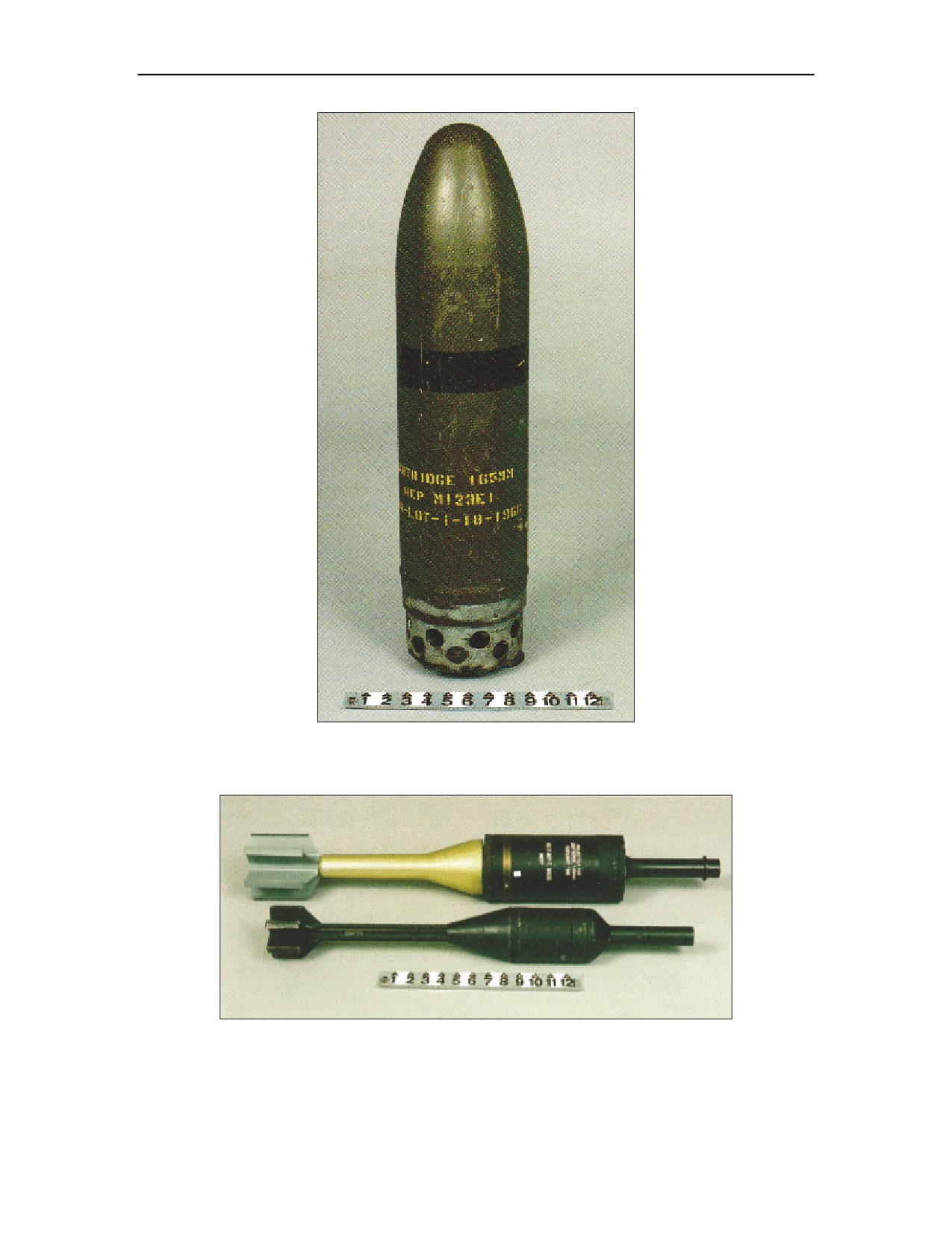
Figure C-6. Spin stabilized projectile 165 millimeter HEP
NEW: less than 35 pounds
Figure C-7. Fin stabilized projectiles 90 millimeter (bottom) and 120 millimeter high
explosive antitank (HEAT) (top)
NEW: less than 5 pounds per item
C-4
FM 4-30.51
13 July 2006

Projected Ordnance Identification and Net Explosive Weight (NEW)
Figure C-8. Fin stabilized projectiles
NEW: less than 5 pounds per item
Figure C-9. Folding fin stabilized HEAT projectiles
NEW: less than 5 pounds per item
13 July 2006
FM 4-30.51
C-5

Appendix C
MORTARS
Figure C-10. Fin stabilized mortars 60 millimeter and below
NEW: less than 5 pounds per item
Figure C-11. Fin stabilized mortars 82 millimeter (top) and 100 millimeter recoilless rifle
projectile (bottom)
NEW: less than 5 pounds per item
C-6
FM 4-30.51
13 July 2006

Projected Ordnance Identification and Net Explosive Weight (NEW)
Figure C-12. Fin stabilized mortars 81 Millimeter and 120 millimeter
NEW: less than 5 pounds per item
Figure C-13. Spin stabilized mortars 4.2 HE (bottom) and illumination (top)
NEW: less than 10 pounds per item
13 July 2006
FM 4-30.51
C-7
Appendix C
ROCKETS
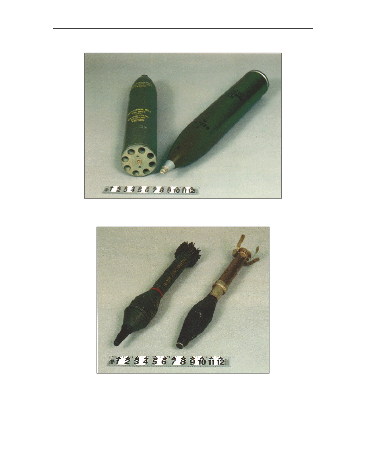
Figure C-14. Spin stabilized rockets 128 millimeter (left) and 132 millimeter (right)
NEW: less than 10 pounds per item
Figure C-15. Fin stabilized HEAT rockets
NEW: less than 3 pounds per item
C-8
FM 4-30.51
13 July 2006

Projected Ordnance Identification and Net Explosive Weight (NEW)
Figure C-16. Fin stabilized rocket 3.5 inch HEAT
NEW: less than 5 pounds per item
Figure C-17. Fin stabilized rocket
NEW: less than 10 pounds per item
Figure C-18. Fin stabilized rocket 2.75 inch
NEW: less than 10 pounds per item
Figure C-19. Fin stabilized rocket 132 millimeter
NEW: less than 20 pounds per item
13 July 2006
FM 4-30.51
C-9

Appendix C
Figure C-20. Fin stabilized rocket 122 millimeter
NEW: less than 20 pounds per item
GUIDED MISSILES
Figure C-21. Dragon guided missile
NEW: less than 10 pounds per item
C-10
FM 4-30.51
13 July 2006

Projected Ordnance Identification and Net Explosive Weight (NEW)
Figure C-22. TOW guided missile
NEW: less than 10 pounds per item
Figure C-23. HAWK guided missile
NEW: less than 40 pounds per item
13 July 2006
FM 4-30.51
C-11

Appendix C
RIFLE GRENADES
Figure C-24. AP rifle grenades
NEW: less than 1 pound per item
Figure C-25. HEAT rifle grenades
NEW: less than 3 pounds per item
C-12
FM 4-30.51
13 July 2006

Projected Ordnance Identification and Net Explosive Weight (NEW)
Figure C-26. Former Soviet Union rifle grenades, RPG models HEAT
NEW: less than 5 pounds per item
Figure C-27. Former Yugoslavia rifle grenades HEAT (bottom) and HE (top)
NEW: less than 5 pound
13 July 2006
FM 4-30.51
C-13
This page intentionally left blank.

Appendix D
Thrown Ordnance Identification and Net Explosive Weight
(NEW)
FRAGMENTATION GRENADES
Figure D-1. Fragmentation grenades
NEW: less than 2 pounds per item
13 July 2006
FM 4-30.51
D-1

Appendix D
ANTITANK GRENADES
Figure D-2. HEAT grenades
NEW: less than 2 pounds per item
SMOKE GRENADES
NOTE: These grenades do not have a NEW concern, although bursting WP grenades have a
15-meter bursting radius.
Figure D-3. Smoke grenades burning type (left) and bursting type (middle and right)
NEW: Not applicable
D-2
FM 4-30.51
13 July 2006

Thrown Ordnance Identification and Net Explosive Weight (NEW)
Figure D-4. Riot control CS grenades
NEW: Not applicable
ILLUMINATION GRENADES
Figure D-5. Illumination grenade
NEW: Not applicable
13 July 2006
FM 4-30.51
D-3
This page intentionally left blank.

Appendix E
Placed Ordnance Identification and Net Explosive Weight
(NEW)
ANTIPERSONNEL MINES
Figure E-1. AP land mines
NEW: less than 0.5 pound per item
Figure E-2. AP land mines
NEW: less than 2 pounds per item
13 July 2006
FM 4-30.51
E-1

Appendix E
ANTITANK MINES
Figure E-3. AT/anti-vehicular land mines
NEW: less than 15 pounds per item
Figure E-4. AT/anti-vehicular land mines
NEW: less than 20 pounds per item
E-2
FM 4-30.51
13 July 2006

Placed Ordnance Identification and Net Explosive Weight (NEW)
Figure E-5. AT/anti-vehicular land mines
NEW: less than 6 pounds per item
Figure E-6. AT/anti-vehicular land mines
NEW: less than 15 pounds per item
Figure E-7. AT/anti-vehicular land mines
NEW: less than 15 pounds per item
13 July 2006
FM 4-30.51
E-3
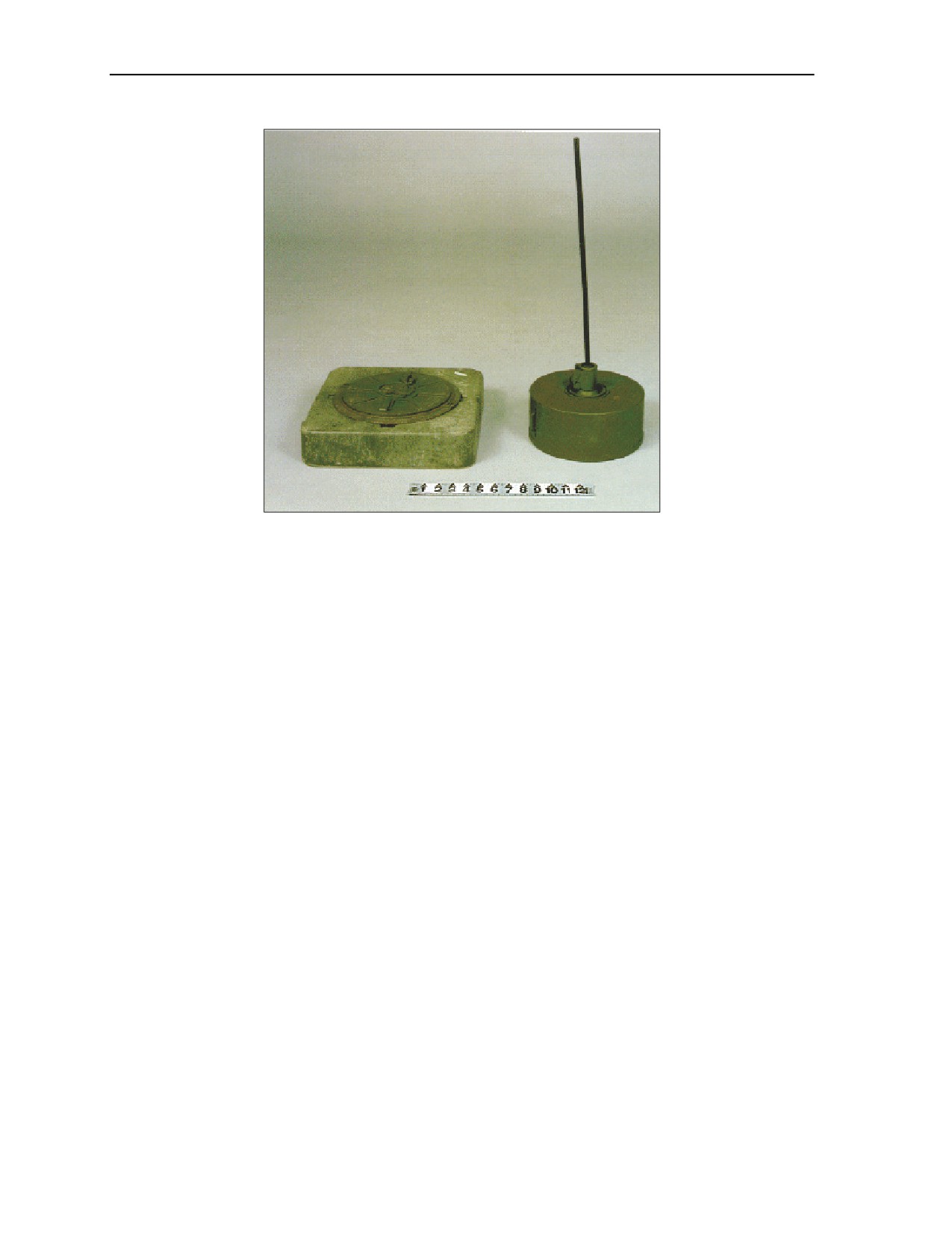
Appendix E
Figure E-8. AT/anti-vehicular land mines
NEW: less than 22 pounds per item
E-4
FM 4-30.51
13 July 2006
Glossary
Acronym/Term
Definition
AMAT
antimateriel
AP
armor piercing
AP
antipersonnel
APFSDS
armor-piercing fin-stabilized, discarding sabot
AT
antitank
BFA
battlefield functional area
CAM
chemical agent monitor
CBRNE
chemical, biological, radiological, nuclear, and high yield explosive
CEA
captured enemy ammunition
CS
combat support
CSS
combat service support
DOD
Department of Defense
DP
dual purpose
DU
depleted uranium
EH
explosive hazards
EMR
electromagnetic radiation
EOCA
explosive ordnance clearance agents
EOD
explosive ordnance disposal
EOR
explosive ordnance reconnaissance
FASCAM
family of scatterable mines
FM
field manual
FMFM
fleet marine force manual
GTA
graphic training aid
HE
high explosive
HEAT
high explosive antitank
HEP
high explosive plastic
HQ
headquarters
IED
improvised explosive devices
MAGTF
Marine Air ground task force
MCRP
Marine Corps
MCWP
Marine Corps warfighting publication
MEDEVAC
medical evacuation
mission, enemy, terrain and weather, troops and support available—time
METT-T
available
MICLIC
mine clearing line charge
NATO
North Atlantic Treaty Organization
13 July 2006
FM 4-30.51
Glossary-1
Glossary
NEW
net explosive weight
OMEMS
Ordnance Munitions and Electronic Maintenance School
OPORD
operation order
PATRIOT
phased array tracking radar intercept on traget
RAAMS
remote antiarmor mine syatem
RPG
rocket propelled grenade
SMCT
Soldier’s Manual of Common Tasks
SOI
signal operating instructions
SOP
standing operating procedures
STANAG
standardization agreement
STP
Soldier Training Publication
TASC
Training Aids Support Center
TOW
tube-launched optically-tracked wire-guided
TRADOC
Training and Doctrine Command
US
United States
UIC
unit identification code
UXO
unexploded ordnance
WP
white phosphorus
Glossary-2
FM 4-30.51
13 July 2006
References
SOURCES USED
These are the sources quoted or paraphrased in this publication.
JOINT PUBLICATIONS
CJCSM 3500.04C, Universal Joint Task List (UJTL). 1 Jul 2002
JP 1-02, Department of Defense Dictionary of Military and Associated Terms, 12 Apr 2001
ARMY PUBLICATIONS
AR 75-15, Responsibilities and Procedures for Explosive Ordnance Disposal, 22 Feb 2005
FM 1-02, Operational Terms and Graphics, 21 Sep 2004
FM 3-0, Operations, 14 Jun 2001
FMI 3-07.22, Counterinsurgency Operations, Aug 2004
FM 3-34, Engineer Operations, 2 Jan 2004
FM 4-0, Combat Service Support, 29 Aug 2003
FM 5-0, Army Planning and Orders Production, 20 Jan 2005
FM 5-34, Engineer Field Data, 30 Aug 1999
FM 9-15, Explosive Ordnance Disposal Service and Unit Operations, 20 Mar 1989
FM 20-32, Mine/Counter Mine Operations, 1 April 2005
FM 34-130, Intelligence Preparation of the Battlefield, 8 Jul 1994
FM 90-13-1, Combined Arms Breaching Techniques, 28 Feb 1991
GTS 9-12-1, Unexploded Ordnance Procedures
Instructional Video No. 710288 “The UXO Hazard”
Safety Video No. 709919 “Danger UXO”
STP 21-1-SMCT, Soldier’s Manual of Common Tasks, Skill Level 1, 11 Oct 2005
STP 21-I-MQS, Military Qualification Standards I Manual of Common Tasks (Recommissioning
Requirements), 31 May 1990.
STP 21-II-MQS, Military Qualification Standards II Manual of Common Tasks (for Lieutenants and
Captains), 31 January 1991.
MARINE PUBLICATIONS
FMFM 13-8, MAGTF Explosive Ordnance Disposal, 20 Dec 1993.
FMFRP 13-5, Engineer Field Data, 30 Aug 1999.
MCWP 3-17.3, MAGTF Breaching Operations, 13 June 1994.
DOCUMENTS NEEDED - NONE
READINGS RECOMMENDED - NONE
13 July 2006
FM 4-30.51
References-1
This page intentionally left blank.
Index
Index
Former Soviet Union markings
Placement and Size of
A
for chemical munitions, A-5
Barricades, 3-3
Ammunition Color Codes, A-1
Fragmentation, A-5, D-1
PRIORITIZING THE SPOT
Antipersonnel Mines, 2-21
Fragmentation Grenades, 2-18
REPORT, 4-2
antitank, C-4
Fuzes, 2-3
PRIORITY BASIS, 4-2
Antitank Grenades, 2-19
PROJECTED ORDNANCE, 2-
Antitank Mines, 2-22
10
G
AP, C-12, E-1
projectiles, C-4, C-5
ARMY EOCA LIMITATIONS,
GENERAL SAFETY
PROJECTILES, 2-10
6-2
GUIDELINES, 1-1
PROTECTIVE MEASURES, 3-
ARMY EXPLOSIVE
grenades, C-12, C-13, D-1, D-2,
2
ORDNANCE CLEARANCE
D-3
PURPOSE, vii
AGENT, 6-1
GUIDED MISSILES, 2-16
AT, E-2, E-3, E-4
R
Attached Dispensers, 2-6
I
Recognize UXO, 2-1
Identification of DU UXO, 2-12
Report the UXO Hazard, 4-1
B
illumination, C-7
RIFLE GRENADES, 2-17
Barricade, 3-2
Illumination, A-5, D-3
rocket, C-9, C-10
Barricade Types
Illumination Grenades, 2-20
rockets, C-8
Circular; Semicircular, 3-5
IMMEDIATE ACTIONS, 5-1
ROCKETS, 2-14
Bombs, 2-1
Interlocking sandbags, 3-4
BREACHING TECHNIQUES,
Isolate, 3-2
S
5-2
SCOPE, vii
L
Self-Extraction From UXO
C
land mines, E-1, E-2, E-3, E-4
Hazards, 5-1
CAPABILITIES, 6-1
Large UXO, 3-4
Semicircular placement of
Complete circular placement of
barricade, 3-5
barricade, 3-5
SITUATIONAL
M
Containment, 5-4
ASSESSMENT, 5-2
Small UXO, 3-4
MARK UXO, 3-6
Smoke, A-5, D-2
D
Marking, A-5
Smoke Grenades, 2-19
Medium UXO, 3-4
DEPLETED URANIUM (DU),
stabilized, C-3, C-4, C-5, C-6, C-
Mine-Clearing Line Charge, 5-3
2-12
MORTARS, 2-14
7, C-8, C-9, C-10
DETECTION, 5-1
STABILIZING DEVICES, 2-3
DISPENSERS, 2-5
Standard UXO marker, 3-6
N
SUBMUNITIONS, 2-6
Dropped Dispensers, 2-6
DROPPED ORDNANCE, 2-1
SUPPORT REQUIREMENTS,
net explosive weights (NEW), 2-
6-1
1
E
NEW, C-3, C-4, C-5, C-6, C-7,
C-8, C-9, C-10, C-11, C-12,
T
ENGINEER EQUIPMENT
C-13, D-1, D-2, E-1, E-3
(HEAVY-FORCE
nonessential personnel, 3-2
Take Immediate Action, 3-1
BREACHING), 5-3
Thrown, D-1
Evacuate, 3-2
THROWN ORDNANCE, 2-18
O
TRAINING STRATEGY, viii
EXPLOSIVE CHARGES, 5-3
EXPLOSIVE HAZARDS SPOT
Offensive Grenades, 2-19
REPORT, 4-1
OTHER SUPPORTING
U
ORGANIZATIONS, 6-1
US and NATO color codes, A-2
F
USER INFORMATION, viii
P
UXO CONSIDERATION FOR
Former Soviet Union color codes
for bombs, A-5
SELF EVACUATION, 5-3
Placed Explosive Charge, 5-4
UXO Direct-Fire Weapons, 5-4
Former Soviet Union color codes
PLACED ORDNANCE, 2-21
for projectiles, A-5
13 July 2006
FM 4-30.51
1
UXO LOCATIONS AND
W
THREATS, 1-1
UXO Response to the
Wall barricade placement, 3-6
Battlefield, 6-1
Index-2
FM 4-30.51
13 July 2006
FM 4-30.51 (FM 21-16)
MCRP 3-17.2A
13 July 2006
By Order of the Secretary of the Army:
PETER J. SCHOOMAKER
General, United States Army
Chief of Staff
Official:
JOYCE E. MORROW
Administrative Assistant to the
Secretary of the Army
0617302
DISTRIBUTION:
Active Army, Army National Guard, and U. S. Army Reserve: Not to be
distributed. Electronic Media Only.
PIN: 083358-000
OCIO-ITS Security Policy Manual
Office of the Chief Information Officer (OCIO),
Information Technology Services (ITS)
• Farm Service Agency
• Natural Resources Conservation Service
• Rural Development
November 29, 2004
Administrative Bulletin
DR 3602-001
Final
Version 1.0
UNITED STATES DEPARTMENT OF AGRICULTURE
Office of the Chief Information Officer (OCIO), Information Technology Services (ITS)
Washington, DC 20250
FOR OFFICIAL USE ONLY
Revision History
Release No.
Date
Revision Description
Original Draft
09/04/2003
Original Draft
Version
Final Version
Incorporated suggestions made by review team.
11/29/2004
1.0
Assigned Directives System Numbering scheme for Security
Final Version
12/02/2004
documents. Document’s first release as an Administrative
1.0
Bulletin.
OCIO-ITS Security Policy Manual - FINAL - Version 1.0
Page i
Number 3602-001
FOR OFFICIAL USE ONLY
Table of Contents
INTRODUCTION TO THE OCIO-ITS SECURITY POLICY MANUAL
1
1.
Purpose
1
2.
Scope
1
3.
Special Instructions/Cancellations
1
4.
Authorities
1
a.
Executive Branch Policy
1
b.
Applicable Laws, Guidelines, Regulations, and Guidance Directives
2
c.
National Institute of Standards and Technology (NIST) Special Publications
4
d.
USDA Cyber Security Policy
4
5.
OCIO-ITS Security Policy Summary
4
6.
Security Policy Administration
8
a.
Security Policies
8
b.
Security Program Plans, Procedures, Standards and Guidelines
9
c.
Security Administration
9
d.
Security Violations
9
7.
Waiver Requirements
9
8.
Roles and Responsibilities
10
a.
USDA Associate OCIO for Cyber Security
10
b.
OCIO-ITS Chief Information Officer (CIO)
10
c.
OCIO-ITS Information Systems Security Program Manager (ISSPM)
10
d.
Senior Management, Line Managers, Division Directors, System Managers, and Supervisors
11
e.
System, Network, and Firewall Administrators
11
f.
End Users
12
1.
CHAPTER ONE: ACCEPTABLE USE SECURITY POLICY
14
a.
General Policy Statement
14
b.
Policy Detail
14
(1).
Official Business
14
(2).
Rules of Behavior
14
(3).
Personal Use
15
(4).
E-Mail Use
16
(5).
Internet Use
17
2.
CHAPTER TWO: AUDIT SECURITY POLICY
19
a.
General Policy Statement
19
b.
Policy Detail
19
(1).
Security Audit
19
(2).
Security Audit Follow-Up
20
3.
CHAPTER THREE: AUTHORIZATION AND ACCESS CONTROL SECURITY POLICY
21
a.
General Policy Statement
21
b.
Policy Detail
21
(1).
Authorization and Access Guidelines
21
(2).
User Account and Password Guidelines
21
(3).
Administrative and Non-User Account and Password Guidelines
23
(4).
Periodic Validation of User Access and Account Privileges
24
(5).
Administrative Guidance for User Passwords
25
4.
CHAPTER FOUR: CAPITAL PLANNING AND INVESTMENT CONTROL (CPIC) SECURITY
POLICY
26
OCIO-ITS Security Policy Manual - FINAL - Version 1.0
Page ii
Number 3602-001
FOR OFFICIAL USE ONLY
a.
General Policy Statement
26
b.
Policy Detail
26
5.
CHAPTER FIVE: CERTIFICATION AND ACCREDITATION SECURITY POLICY
27
a.
General Policy Statement
27
b.
Policy Detail
27
(1).
Security Certification and Accreditation
27
(2).
Federal Information Security Management Act
27
(3).
Certification and Accreditation Program
27
(4).
Identification of Included Information Systems
27
(5).
Participation
27
(6).
Site Certification and Accreditation
28
(7).
New Information Systems
28
(8).
Commercial Off-The-Shelf and Government Off-The-Shelf Applications
28
(9).
Existing and Outdated Information Systems
28
(10).
Periodic Review of Information Systems
28
(11).
Non-OCIO-ITS Systems
28
(12).
Non-OCIO-ITS Sites and Facilities
29
6.
CHAPTER SIX: CONTINGENCY AND DISASTER RECOVERY SECURITY POLICY
30
a.
General Policy Statement
30
b.
Policy Detail
30
(1).
Contingency and Disaster Recovery Planning
30
(2).
Alternate Operating Capability, System Redundancy, and Back-Up/Recovery
31
7.
CHAPTER SEVEN: DATA MANAGEMENT SECURITY POLICY
33
a.
General Policy Statement
33
b.
Policy Detail
33
(1).
Data Security
33
(2).
Data Usage
34
(3).
Data Ownership
34
(4).
Data Media Marking
34
(5).
Data Protection
34
(6).
Data Sharing
35
(7).
Data Transmission
35
(8).
Data Storage
35
(9).
Data Disposal
35
(10).
Data Content
35
(11).
Data Classification
35
8.
CHAPTER EIGHT: FIREWALL MANAGEMENT SECURITY POLICY
36
a.
General Policy Statement
36
b.
Policy Detail
36
(1).
Firewall Protocols
36
(2).
Firewall Management Access
36
(3).
Firewall Configuration
36
(4).
Firewall Physical Security
37
(5).
Firewall Logs
37
(6).
Incident Reporting
37
9.
CHAPTER NINE: GOVERNMENT-OWNED LAPTOP COMPUTERS AND PED SECURITY
POLICY
38
a.
General Policy Statement
38
OCIO-ITS Security Policy Manual - FINAL - Version 1.0
Page iii
Number 3602-001
FOR OFFICIAL USE ONLY
b. Policy Detail
38
(1).
Classification of Government-Owned Laptop Computers
38
(2).
Government-Owned Laptop Computer Security
38
(3).
Government-Owned Portable Electronic Devices (PED)
40
10.
CHAPTER TEN: INCIDENT IDENTIFICATION, DECLARATION, REPORTING, AND HANDLING
SECURITY POLICY
42
a.
General Policy Statement
42
b.
Policy Detail
42
(1).
Computer Security Incidents
42
(2).
Reporting Process
43
11.
CHAPTER ELEVEN: INFORMATION CLASSIFICATION SECURITY POLICY
44
a.
General Policy Statement
44
b.
Policy Detail
44
(1).
Sensitive But Unclassified (SBU) Information Protection
44
(2).
For Official Use Only (FOUO) Information Protection
45
(3).
Encryption
45
12.
CHAPTER TWELVE: INTRUSION DETECTION MANAGEMENT SECURITY POLICY
48
a.
General Policy Statement
48
b.
Policy Detail
48
(1).
IDS Access
48
(2).
IDS Configuration Standards
48
(3).
IDS Physical Security
48
(4).
IDS Logs
48
(5).
IDS Implementation
49
(6).
Change Request
49
13.
CHAPTER THIRTEEN: MEDIA SANITATION AND DISPOSAL SECURITY POLICY
50
a.
General Policy Statement
50
b.
Policy Detail
50
(1).
Sanitization of IT Equipment and Electronic Media
50
(2).
Sanitization of Hard Drives
50
(3).
Overwriting Specifications
50
(4).
Degaussing Specifications
51
(5).
Physical Destruction
51
(6).
Sanitization of Other Computer Media
51
(7).
Disposal of OCIO-ITS Equipment
51
14.
CHAPTER FOURTEEN: NETWORK ACCESS SECURITY POLICY
52
a.
General Policy Statement
52
b.
Policy Detail
52
(1).
Warning Banners
52
(2).
Remote Access
52
(3).
Telework
54
(4).
Wireless Technology
56
15.
CHAPTER FIFTEEN: NON-GOVERNMENT OWNED LAPTOP COMPUTER AND PED
SECURITY POLICY
57
a.
General Policy Statement
57
b.
Policy Detail
57
OCIO-ITS Security Policy Manual - FINAL - Version 1.0
Page iv
Number 3602-001
FOR OFFICIAL USE ONLY
(1).
Non-Government Owned Laptop Computers Security
57
(2).
Non-Government Owned Portable Electronic Devices (PED)
58
16.
CHAPTER SIXTEEN: PATCH MANAGEMENT SECURITY POLICY
59
a.
General Policy Statement
59
b.
Policy Detail
59
(1).
Patch Prioritization and Scheduling
59
(2).
Patch Testing
59
(3).
Change Management
59
(4).
Audit and Assessment
60
(5).
Notification of Users
60
17.
CHAPTER SEVENTEEN: PHYSICAL ACCESS SECURITY POLICY
61
a.
General Policy Statement
61
b.
Policy Detail
61
(1).
Large IT Facility Security Requirements
61
(2).
IT Restricted Space within Large Office IT Facilities
61
(3).
Facility Security for Field Offices
64
18.
CHAPTER EIGHTTEEN: PRINTER MANAGEMENT SECURITY POLICY
66
a.
General Policy Statement
66
b.
Policy Detail
66
(1).
Printer Management Access
66
(2).
Waiver and Configuration Change Requests
66
(3).
Network and Multipurpose Printer Services
66
(4).
Special Provisions for Large Scale Printer/Copy Stations
66
(5).
Incident Reporting and Response
67
19.
CHAPTER NINETEEN: PRIVACY IMPACT ASSESSMENT SECURITY POLICY
68
a.
General Policy Statement
68
b.
Policy Detail
68
(1).
Privacy Impact Assessment
68
(2).
SDLC Methodology
68
20.
CHAPTER TWENTY: RISK MANAGEMENT SECURITY POLICY
70
a.
General Policy Statement
70
b.
Policy Detail
70
21.
CHAPTER TWENTY-ONE: ROUTER AND SWITCH MANAGEMENT SECURITY POLICY
71
a.
General Policy Statement
71
b.
Policy Detail
71
(1).
Router and Switch Configuration
71
(2).
Router and Switch Management
71
(3).
Router and Switch Management Access
72
(4).
Router and Switch Information Access
72
(5).
Router and Switch Logs
72
(6).
Change Request
72
(7).
Router and Switch Implementation
72
(8).
Implied Authority
73
(9).
Incident Reporting and Response
73
OCIO-ITS Security Policy Manual - FINAL - Version 1.0
Page v
Number 3602-001
FOR OFFICIAL USE ONLY
22.
CHAPTER TWENTY-TWO: SECURITY ARCHITECTURE FRAMEWORK MANAGEMENT
SECURITY POLICY
74
a.
General Policy Statement
74
b.
Policy Detail
74
23.
CHAPTER TWENTY-THREE: SECURITY AWARENESS, TRAINING, AND EDUCATION
SECURITY POLICY
75
a.
General Policy Statement
75
b.
Policy Detail
75
24.
CHAPTER TWENTY-FOUR: SECURITY PLAN MANAGEMENT SECURITY POLICY
76
a.
General Policy Statement
76
(1).
Federal Requirements
76
(2).
Security Plans
76
b.
Policy Detail
76
(1).
Security Plan Development
76
(2).
Determining General Support Systems and Major Applications
77
25.
CHAPTER TWENTY-FIVE: SERVER MANAGEMENT SECURITY POLICY
78
a.
General Policy Statement
78
b.
Policy Detail
78
(1).
Server Configuration
78
(2).
Server Specification Settings
78
(3).
Server Management Access
79
(4).
Server Classification
79
(5).
Server Information Access
79
(6).
Server Logs
79
(7).
Server Implementation
80
(8).
Server Change Requests
80
(9).
Server Services
80
(10).
Implied Authority
80
(11).
Incident Reporting and Response
80
26.
CHAPTER TWENTY-SIX: SYSTEMS DEVELOPMENT LIFE CYCLE SECURITY POLICY
81
a.
General Policy Statement
81
b.
Policy Detail
81
(1).
Initiation Phase
81
(2).
Development Phase
82
(3).
Implementation Phase
83
(4).
Operations and Maintenance Phase
83
(5).
Disposition Phase
84
27.
CHAPTER TWENTY-SEVEN: VIRUS PROTECTION SECURITY POLICY
85
a.
General Policy Statement
85
b.
Policy Detail
85
(1).
Virus Protected Systems
85
(2).
Virus Software Configurations and Scanning Policy
85
28.
CHAPTER TWENTY-EIGHT: VULNERABILITY SCAN SECURITY POLICY
87
a.
General Policy Statement
87
b.
Policy Detail
87
(1).
New Equipment/Equipment Upgrade
87
OCIO-ITS Security Policy Manual - FINAL - Version 1.0
Page vi
Number 3602-001
FOR OFFICIAL USE ONLY