Military reference books and manuals (2009-2023, Volume 8) - page 30
Appendix B
Special Forces Area Assessment
This appendix provides an outline format for an area assessment. This format
provides a systematic means for compiling and retaining essential information to
support SF operations. Although the basic outline is general, it is flexible enough to
permit detailed coverage of a given JSOA.
IMMEDIATE—INITIAL ASSESSMENT
B-1. The initial assessment includes items essential to the operational detachment immediately following
infiltration. Detachments must satisfy these requirements as soon as possible after arriving in the JSOA.
This initial information should include the following:
z
Location and orientation.
z
Physical condition of the detachment.
z
Overall security, to include the—
Immediate area.
Attitude of the local populace.
Local enemy situation.
Status of the local resistance element.
SUBSEQUENT—PRINCIPAL ASSESSMENT
B-2. The principal assessment is a continuous operation that includes collection efforts that support the
continued planning and conduct of operations. The principal assessment forms the basis for all of the
detachment’s subsequent activities in the JSOA. Figure B-1, pages B-1 through B-5, shows the areas that
the principal assessment should encompass.
Principal Assessment
The Enemy:
Disposition.
Composition, identification, and strength.
Organization, armament, and equipment.
Degree of training, morale, and combat effectiveness.
Operations, such as:
Recent and current activities of the unit.
Counterguerrilla activities and capabilities, with particular attention to reconnaissance units, special troops
(airborne, mountain, ranger), rotary-wing or vertical-lift aviation units, counterintelligence units, and units
having a mass CBRNE delivery capability.
Unit areas of responsibility.
Daily routine of the units.
Figure B-1. Sample principal assessment
30 November 2010
TC 18-01
B-1
Appendix B
Principal Assessment (continued)
The Enemy (continued):
Logistics support, to include the following:
Installations and facilities.
Supply routes.
Methods of troop movement.
Past and current reprisal actions.
Security and Police Units:
Dependability and reliability to the existing regime or the occupying power.
Disposition.
Composition, identification, and strength.
Organization, armament, and equipment.
Degree of training, morale, and efficiency.
Use and effectiveness of informers.
Influence on and relations with the local populace.
Security measures over public utilities and government installations.
Civil Government:
Control and restrictions, such as—
Documentation.
Rationing.
Travel and movement restrictions.
Blackouts and curfews.
Current value of money and wage scales.
The extent and effect of the black market.
Political restrictions.
Religious restrictions.
Control and operation of industry, utilities, agriculture, and transportation.
Civilian Populace:
Attitudes toward the existing regime or occupying power.
Attitudes toward the resistance movement.
Reaction to U.S. support of the resistance.
Reaction to enemy activities in the country, specifically that portion in the UWOA.
General health and well-being.
Potential Targets:
Railroads.
Telecommunication.
Petroleum, oils, and lubricants.
Electric power.
Military storage and supply.
Military HQ and installations.
Radar and electronic devices.
Highways.
Figure B-1. Sample principal assessment (continued)
B-2
TC 18-01
30 November 2010
Special Forces Area Assessment
Principal Assessment (continued)
Potential Targets (continued):
Inland waterways and canals.
Seaports.
Natural and synthetic gas lines.
Industrial plants.
Key personalities.
Weather:
Precipitation, cloud cover, temperature, visibility, and seasonal changes.
Wind speed and direction.
Light data (BMNT, EENT, sunrise, sunset, moonrise, and moonset).
Terrain:
Location of areas suitable for guerrilla bases, units, and other installations.
Potential LZs, DZs, and other reception sites.
Routes suitable for—
Guerrillas.
Enemy forces.
Barriers to movement.
Seasonal effect of the weather on terrain and visibility.
Resistance Movement:
Guerrillas:
Disposition, strength, and composition.
Organization, armament, and equipment.
Status of training, morale, and combat effectiveness.
Operations to date.
Cooperation and coordination between various existing groups.
General attitude toward the United States, the enemy, and various elements of the civilian populace.
Motivation of the various groups and their receptivity to U.S. presence.
Caliber of senior and subordinate leadership.
Health of guerrillas.
Auxiliaries and the underground:
Disposition, strength, and degree of organization.
General effectiveness and type of support.
Motivation and reliability.
Responsiveness to guerrilla or resistance leaders.
General attitude toward the United States, the enemy, and various guerrilla groups.
Logistics Capability of the Area:
Availability of food stocks and water. Include any health-related water restrictions.
Agricultural capability.
Type and availability of all categories of transportation.
Types and location of civilian services available for the manufacture and repair of equipment and clothing.
Supplies locally available, including type and amount.
Medical facilities, including personnel, medical supplies, and equipment.
Enemy supply sources accessible to the resistance.
Figure B-1. Sample principal assessment (continued)
30 November 2010
TC 18-01
B-3
Appendix B
Principal Assessment (continued)
Preventive Medicine:
Weather:
Area cold-weather impact on causes, treatment, and prevention of cold-weather injuries.
Area hot-weather impact on causes, treatment, and prevention of hot-weather injuries.
Terrain impact on evacuation and medical resupply.
Indigenous personnel:
Physical characteristics of local people, including endurance, ability to carry loads, and performance
of other physical feats.
Symbolism attached to various articles of clothing and jewelry, such as amulets.
Attitudes:
Taboos and other psychological attributes present in the society.
Rites and practices unconventional healers use during illness, including symbolic rites and Western
medicine in use.
Response of indigenous personnel to feelings, such as fear, happiness, anger, and sadness.
Housing:
Analysis of the physical layout of the community.
Infestation of ectoparasites and vermin.
Food:
Food cultivation for consumption, including types of food.
Influence of seasons in the AO on diet, including any migration.
Types of foods provided by U.S. personnel, including preferences and rejections of foods.
Types of crops raised.
Water:
Urban water supply.
Rural water supply, including numbers and types.
Water treatment plants in use.
Water treatment in rural areas. Attitudes of indigenous personnel toward standard U.S. purification
methods.
Sewage disposal (when applicable):
Types and locations of sewage treatment plants.
System used in remote areas to dispose of human excrement, offal, and dead animals
or humans.
Attitudes of indigenous personnel to standard U.S. hygiene methods, such as the use of latrines.
Epidemiology:
What specific diseases in each of the following two major categories are present among the guerrillas,
their dependents, or their animals?
Domestic animals:
Types of domestic animals present.
Typical forage.
Supplemental animal food supply, including food supplements.
Animal housing (penned or free-roaming).
Religious symbolism or taboos locals associate with animals
(for example, an animal
considered sacred).
Figure B-1. Sample principal assessment (continued)
B-4
TC 18-01
30 November 2010
Special Forces Area Assessment
Principal Assessment (continued)
Preventive Medicine (continued):
Animal sacrifices for religious purposes.
Availability of local veterinarians for animal treatment and postmortem inspections of meats.
Training of local veterinarians.
Local flora and fauna:
Species of birds, large and small mammals, reptiles, and arthropods present in the area.
Describe unknown varieties for survival purposes. Keep a record.
Area plants known to be toxic through contact with the skin, inhalation of smoke from burning
vegetation, or through ingestion.
Figure B-1. Sample principal assessment (continued)
30 November 2010
TC 18-01
B-5
Appendix C
Sample Training Program of Instruction
for Resistance Forces
The master training program for the 10-day and 30-day leadership schools provide
indigenous leaders and potential leaders with general knowledge of the subjects to
teach subordinate personnel. Trainers place the primary emphasis on the role of the
leader or commander in preparing leaders to supervise the activities of their
subordinates. Trainers assume that most individuals in leadership positions have prior
military service. Attendees should already possess a basic knowledge of the subjects
the trainers will cover.
EXAMPLE OF A 30-DAY LEADERSHIP COURSE
C-1. Figure C-1, pages C-1 and C-2, is an example of a 30-day master training program that leaders may
use as a basis for preparing individual master training programs for each indigenous unit.
Master Training Program, 30-Day Leadership Course
Hours
Subject
Scope
Day
Night
Total
PE
Map reading, map orientation with compass,
Map Reading and
self-location, azimuth determination, and
14
10
24
(20)
Compass
compass use at day and night.
Basic wound treatment, infection prevention,
Field Aid,
simple bandaging, pressure points, shock
Field Sanitation,
prevention, splint placement, litter construction
6
4
10
(7)
and Survival
and use, field sanitation measures with water
supply, waste disposal, and personal hygiene.
Camouflage; cover; concealment; movement;
observation; reporting; discipline; sounds;
hand-to-hand combat; combat formations and
Individual Tactical
night movement; night camouflage; preparation
Training
26
9
35
(31)
of equipment and clothing; night visions,
(Day and Night)
sounds, and observation; night security and
formations; message writing; immediate action
drills; and security of operational bases.
Planning; organization; preparation; formations;
commands; control; security; communications;
patrol reporting; objectives; target selection;
Small-Unit Tactics,
raid force organization; reconnaissance and
Raids, Patrols, and
intelligence planning; raid preparation,
26
44
70
(60)
Ambushes
movement, deployment, and conduct; raid
(Day and Night)
force disengagement and withdrawal; ambush
characteristics, definition, and objectives;
ambush site selection; ambush force
Figure C-1. Sample master training plan for 30-day leadership course
30 November 2010
TC 18-01
C-1

Appendix C
Master Training Program, 30-Day Leadership Course (continued)
Hours
Subject
Scope
Day
Night
Total
PE
Small-Unit Tactics,
organization; ambush operation phases; planning,
Raids, Patrols, and
preparation, movement, deployment, execution,
Ambushes
disengagement, and withdrawal of ambush forces.
(Day and Night)
Trainers cover all subjects for day and night.
(continued)
Carbine M1 submachine gun, automatic rifle, pistol,
.45-caliber machine guns, and foreign weapons.
U.S. and Foreign
Training includes care and cleaning, loading,
26
9
35
(31)
Weapons
aiming, stoppages, and range firing. Trainers
familiarize trainees with all weapons, as well as day
and night firing
Security measures, information gathering and
reporting, captured documents and materiel,
Intelligence
26
44
70
(60)
prisoner handling and interrogation, and
counterintelligence procedures.
DZ establishment, DZ marking and identification,
Air Operations
DZ security, and transport and reception of
28
10
38
(32)
supplies and equipment.
Nonelectric and electric firing systems, charge
Demolitions
placement and calculation, rail and bridge
21
8
29
(24)
destruction, booby traps, and expedient devices.
Squad Tests
Review and exercise covering all instructions.
23
16
39
(37)
Platoon Tests
Review and exercise covering all instruction.
42
24
66
(63)
Total Hours in Master Program
210
140
350
(304)
Notes:
1. Trainers will use the maximum number of trained, indigenous personnel to assist in training others. Trainers should
identify potential indigenous cadre and leaders. In addition, trainers must identify personnel with substandard leadership
ability, knowledge, skill, or desire.
2. Whenever possible, trainers will integrate intelligence collection, compass instruction, map familiarization, observation
and reporting, individual tactical training, patrolling, weapons, demolitions, and field sanitation.
3. Trainers can break classes down to platoon-size groups whenever possible.
4. Trainers should use practical work exercise, demonstrations, and conferences instead of lectures whenever possible.
5. Trainers must stress small-unit training (patrol, squad, and platoon) and develop teamwork and esprit de corps.
Figure C-1. Sample master training plan for 30-day leadership course (continued)
EXAMPLE OF A 10-DAY LEADERSHIP COURSE
C-2. Upon completion of the 10-day leadership school, the leaders will return to work and train with their
units, thus expanding their knowledge. Figure C-2, pages C-2 and C-3, is an example of 10-day master
training program for a leadership school training select indigenous personnel.
Master Training Program, 10-Day Leadership Course
Hours
Subject
Scope
Day
Night
Total
PE
Map Reading and
Same general scope as in the 30-day program.
4
2
6
(4)
Compass
Include how to read scale and coordinates.
Figure C-2. Sample master training plan for 10-day leadership course
C-2
TC 18-01
30 November 2010

Sample Training Program of Instruction
for Resistance Forces
Master Training Program, 10-Day Leadership Course
Hours
Subject
Scope
Day
Night
Total
PE
Field Aid,
Same general scope as in the 30-day program.
Field Sanitation,
Emphasis on field sanitation and responsibility of
4
4
(1)
and Survival
commanders.
Same general scope as in the 30-day program.
Individual Tactical
Emphasis on security of operational bases,
Training
10
9
19
(16)
movements, formations, night control measures,
(Day and Night)
and duties and responsibilities of commanders.
Small-Unit Tactics,
Same general scope as in the 30-day program.
Raids, Patrols, and
Emphasis on planning, organization, preparation,
10
29
39
(25)
Ambushes
command, control, security, patrol execution,
(Day and Night)
ambushes, and raids.
Same general scope as in the 30-day program.
U.S. and Foreign
Familiarization firing. Primary emphasis on
8
2
10
(7)
Weapons
employment of weapons.
Same general scope as in the 30-day program.
Intelligence
Emphasis on basic intelligence and
6
4
10
(8)
counterintelligence, as well as night vision.
Same general scope as in the 30-day program.
Primary emphasis on selection and reporting of
Air Operations
6
8
14
(11)
DZs, organization of reception committee, and
duties and responsibilities of commanders.
Familiarization with demolition procedures,
Demolition
5
5
(3)
including demonstrating, planning, and safety.
Communication includes available systems,
Communications
communication security, and simple cryptographic
4
4
(2)
systems.
Military leadership traits, principles, indications,
actions, and orders. Responsibilities and duties of
Leadership
the commander. Human behavior problem areas
Principles and
6
6
(4)
and problem-solving process. Selection of junior
Techniques
leaders. Span of control and chain of command.
Combat leadership.
Characteristics of guerrilla warfare; guerrilla
operations, principles, capabilities, and limitations;
organization of operational bases; security; civilian
Tactics and
support; logistics; counterintelligence; combat
7
5
12
(9)
Operations
employment; missions; tactical control measures;
target selection; and mission support site (MSS)
and defensive measures. Responsibilities and
duties of indigenous leaders.
Total Hours in Master Program
70
59
129
(90)
Notes:
1. Identify personnel with substandard leadership ability, knowledge, skill, or desire.
2. Upon completion of leadership school, trainers may schedule one additional day for coordinating and planning future
operations.
3. A suggested arrangement of scheduling is as follows:
Preparation for training and selection of leaders: 29 April-4 May.
Leadership training: 5 May-14 May.
Troop training: 16 May-14 June.
Figure C-1. Sample master training plan for 10-day leadership course (continued)
30 November 2010
TC 18-01
C-3

Appendix C
DATA CARD—PERSONNEL AND TRAINING RECORD
C-3. Figure C-3, pages C-4 and C-5, is an example of a personnel data card that may also serve as a
training record. Using the card for both purposes simplifies record keeping and minimizes the number of
records that personnel must maintain in the AO. The type and amount of information that personnel record
will vary by AO as will the degree of security the U.S. element affords resistance personnel.
Data Card
Personnel and Training Record
1. PERSONNEL DATA
a. JSOA:
FULL NAME:
SERIAL NUMBER:
b. RANK:
DATE OF BIRTH:
PLACE OF BIRTH:
c. UNIT:
DATE OF ENLISTMENT:
d. LAST CIVILIAN ADDRESS:
e. CIVILIAN OCCUPATION:
f. LANGUAGES:
g. SPECIAL SKILLS AND APTITUDES (CIVILIAN) :
h. FINANCIAL DATA:
NAME:
DATE:
AMOUNT PAID:
NAME:
DATE:
AMOUNT PAID:
NAME:
DATE:
AMOUNT PAID:
i. LEFT THUMBPRINT:
RIGHT THUMBPRINT:
j.
PHOTOGRAPH:
k. DATE OF DISCHARGE OR DEMOBILIZATION:
2. TRAINING RECORD
a. BASIC TRAINING:
SUBJECT:
DATE:
b. ADVANCED OR
SPECIALIST TRAINING:
Figure C-3. Data card—personnel and training record
C-4
TC 18-01
30 November 2010

Sample Training Program of Instruction
for Resistance Forces
Data Card (continued)
Personnel and Training Record
c. MILITARY OCCUPATIONAL SPECIALTIES
DEGREE:
AREA OF INTEREST:
LEVEL OF PROFICIENCY:
d. WEAPONS QUALIFICATIONS:
WEAPON:
DEGREE OF SKILL:
e. COMBAT OPERATIONS:
f. AWARDS AND DECORATIONS:
g. WOUNDS OR INJURIES:
TYPE:
DATE:
3. DISCIPLINARY ACTIONS:
DATE OF OFFENSE:
TYPE OF TRIAL:
PUNISHMENT:
Figure C-3. Data card—personnel and training record (continued)
30 November 2010
TC 18-01
C-5
Appendix D
Special Forces Caching
Caching is the process of hiding equipment or materials in a secure storage place with
the intent of recovering the items for future operational use. The ultimate success of
caching depends upon attention to details that may seem unimportant to the untrained
eye. Security factors—such as cover for the caching party, sterility of the items
cached, and removal of any traces of the caching operation—are vital. There are two
other factors vital to successful caching. First, personnel must observe the technical
factors governing the preservation of the items that maintain their usability. Second,
personnel must accurately record data that is essential for recovery. Successful
caching entails careful adherence to the basic principles of clandestine operations, as
well as familiarity with the technicalities of caching.
CACHING CONSIDERATIONS
D-1. Personnel must consider the purpose of their caches. For example, some cached supplies must meet
the emergency needs of personnel unable to access their normal supply sources because of sudden
developments. Caching may help to resolve the supply problems of long-term operations conducted far
from a secure base. Caching could also provide for some anticipated needs of wartime operations in areas
the enemy is likely to overrun.
PLANNING FOR A CACHING OPERATION
D-2. Caching involves selecting the items for caching, procuring those items, and selecting a cache site.
Selection requires a close estimate of items a unit will need for particular operations. Procurement of the
items does not usually present a problem. In fact, the relative ease of procurement before an emergency
arises is one of the prime considerations in favor of caching. When selecting a cache site, planners should
always ensure that the site is accessible not only for emplacement but also for recovery. When planning a
caching operation, the planner must consider the following six basic factors:
z
Purpose and contents of the cache.
z
Anticipated enemy action.
z
Activities of the local population.
z
Intended actions by allied forces.
z
Packaging and transportation.
z
Personnel assets.
PURPOSE AND CONTENTS OF THE CACHE
D-3. Planners must determine the purpose and contents of each cache because these basic factors
influence the location of the cache and the method of hiding. For instance, personnel can cache small barter
items at any secure, accessible site because personnel can easily conceal the items once recovered.
However, it would be difficult for a guerrilla band to conceal rifles once it recovers them. Therefore,
personnel must locate a rifle cache site in an isolated area where they can establish temporary control.
Certain items, such as medical stock, have limited shelf life and require periodic rotation or special storage
considerations, which necessitates the guerrillas having easy access to these items for servicing. Sometimes
it is impossible to locate a cache in the most convenient place for an intended user. Planners must
30 November 2010
TC 18-01
D-1
Appendix D
compromise between logistical objectives and actual possibilities when selecting a cache site. Security is
always the overriding consideration.
ANTICIPATED ENEMY ACTION
D-4. In planning the caching operation, units must consider the capabilities of any intelligence or security
services not participating in the operation. They should also consider the potential hazards the enemy and
its witting or unwitting accomplices present. If the purpose of caching is for wartime operational purposes,
its ultimate success will depend largely on if planners anticipate the various recovery obstacles the enemy
and its accomplices will create if they occupy the area. What are the possibilities that the enemy will
preempt an ideal site by denying access to it? A vacant field surrounded by brush may seem ideal for a
particular cache because it is near several highways, but such a location may also invite the enemy to locate
an ordnance depot in the same place.
ACTIVITIES OF THE LOCAL POPULATION
D-5. Chance circumstances that result in the discovery of the cache are more likely than discovery by
deliberate enemy action. Normal activity, such as building construction, may uncover the cache site or
impede access to it. Planners cannot anticipate these circumstances, but they can attempt to avoid them by
careful and imaginative observation of the prospective cache site and of the people who live near the site.
If planners intend the cache for wartime use, they must project how the residents will react to the pressures
of war and conquest. For example, one likely reaction is caching by the residents to protect their personal
funds and valuables. If caching becomes popular, any likely cache site will receive unusual attention.
INTENDED ACTIONS BY ALLIED FORCES
D-6. Using one cache site for several clandestine operations involves a risk of mutual compromise.
Therefore, planners should rule out suitable caching sites if they have selected them for other clandestine
purposes, such as drops or safe houses. Planners should not locate a site where bombing or other allied
military action will render it inaccessible if occupied. If planners intend the cache for wartime use, the
caching party should avoid key areas, such as locations near key bridges, railroad intersections, power
plants, and munitions factories.
PACKAGING AND TRANSPORTATION
D-7. Asset planners should assess the security needs, potential obstacles, and hazards that a prospective
cache site can present. They should also consider whether they could use the operational assets for
packaging and transporting the package to the site. Caching personnel obtain the best results when
packaging center experts construct the package. Planners must first decide whether the caching party can
securely transport the package from the HQ or the field-packaging center to the cache site in time to meet
the operational schedules. If not, the planners must get the packaging done locally, perhaps in a safe house
located within a few miles of the cache site. If such an arrangement is necessary, limited safe house
possibilities may restrict the choice of cache sites.
PERSONNEL ASSETS
D-8. All personnel directly participating in the emplacement will know the cache location. Therefore,
planners should use their most reliable individuals and minimize the number of participants. Planners must
consider the distance from the person’s residence to the prospective cache site. Participants must consider
their reason or story for conducting this activity. Sometimes transportation and cover difficulties require
planners to locate the cache site within a limited distance of the person’s residence. The above
considerations also apply to the recovery personnel.
D-2
TC 18-01
30 November 2010
Special Forces Caching
CACHING METHODS
D-9. The caching method depends on the situation, which makes it unsound to lay down general rules,
with the exception of suitability. Planners should always think in terms of suitability. For example, the
method most suitable for each cache, considering its specific purpose, the actual situation in the particular
locality, and the changes that may occur if the enemy gains control.
CONCEALMENT
D-10. Concealment requires the use of permanent man-made or natural features to hide or disguise the
cache. Concealment has several advantages. Personnel can usually employ and recover a concealed cache
with minimum time and labor. In addition, dry cave or building caching protects the package from the
elements and requires less-elaborate packaging. In some cases, personnel can readily inspect a concealed
cache from time to time to ensure that it is still usable. However, the chance of accidental discovery—in
addition to all the hazards of wartime—may result in destruction or denial of access to a concealed cache
site. The concealment method, therefore, is most suitable in cases where an exceptionally secure site is
available or where a need for quick access to the cache justifies a calculated sacrifice in security.
Concealment may range from securing small gold coins under a tile in the floor to walling up artillery in
caves.
BURIAL
D-11. Planners can find adequate burial sites almost anywhere. Once in place, a properly buried cache is
generally the best way of achieving lasting security. In contrast to concealment, however, burial in the
ground is a laborious and time-consuming method of caching. The disadvantages of burial are that—
z
Burial usually requires a high-quality container or special wrapping to protect the cache from
moisture, chemicals, and bacteria in the soil.
z
Emplacement or recovery of a buried cache usually takes so long that the operation must be
done after dark unless the site is exceptionally secluded.
z
Identification and location of a buried cache is especially difficult.
SUBMERSION
D-12. Secure concealment submersion sites are difficult to find. In addition, the packager must use a
container that meets such high standards for waterproofing and resistance to external pressure that the use
of field expedients is seldom a workable option. To ensure that a submerged cache remains dry and in
place, planners must determine not only the depth of the water but also the type of bottom, as well as the
currents and other facts that are relatively difficult to obtain.
SITE SELECTION
D-13. The most careful estimates of future operational conditions cannot ensure the accessibility of a cache
when personnel need it. The following paragraphs address site selection considerations.
SELECTION CRITERIA
D-14. Planners consider a site for a cache if it meets the certain qualifications. Cache site selection must
allow personnel to—
z
Locate the site by simple instructions that are unmistakably clear to someone who has never
visited the location. A site may be ideal in every respect, but if it has no distinct, permanent
landmarks within a readily measurable distance, planners must rule it out.
z
Access and egress the site by at least two secure routes. Both primary and alternate routes
should provide natural concealment so that the emplacement party and the recovery party can
visit the site without casual observation.
30 November 2010
TC 18-01
D-3
Appendix D
z
Emplace and recover the cache at the site in all seasons. Snow and frozen ground create special
problems. Snow on the ground is a hazard because it is impossible to erase a trail in the snow.
Planners must consider whether seasonal changes in the foliage will leave the site and the route
dangerously exposed.
MAP SURVEY
D-15. Finding a cache site is often difficult. Usually, a thorough systematic survey of the general area
designated for the cache is required. The survey is best done with a large-scale map of the area, if
available. By scrutinizing the map, the planners can determine whether a particular sector must be ruled out
because of its proximity to factories, homes, busy thoroughfares, or probable military targets in wartime. A
good military-type map will show the positive features in the topography, proximity to adequate roads or
trails, natural concealment (for example, surrounding woods or groves), and adequate drainage. Maps also
show the natural and man-made features in the landscape, which provide indispensable reference points for
locating a cache site, such as confluences of streams, dams and waterfalls, road junctures and distance
markers, villages, bridges, churches, and cemeteries.
PERSONAL RECONNAISSANCE
D-16. A map survey should normally show the location of several promising sites within the general area
planners designate for the cache. To select and pinpoint the best site, a well-qualified observer must
examine each site firsthand. If possible, the individual examining the site should carry adequate maps, a
compass, a drawing pad or board for making sketch maps or tracings, and a metallic measuring line. (A
wire knotted at regular intervals is adequate for measuring. Personnel should not use twine or cloth
measuring tapes because stretching or shrinking will make them inaccurate if they get wet.) If the observer
can carry it securely, he should also carry a probe rod for probing prospective burial sites.
D-17. Since the observer seldom completes a field survey without local residents noticing him, the
explanation for his actions is of importance. The observer’s story must offer a natural explanation for his
exploratory activity in the area. Ordinarily, this means that an observer who is not a known resident of the
area can pose as a tourist or a newcomer with some reason for visiting the area. However, the observer
must develop this story over an extended period before he conducts the actual reconnaissance. If the
observer is a known resident of the area, he cannot suddenly begin hunting, fishing, or wildlife
photography without arousing interest and perhaps suspicion. The observer must build up a reputation for
involvement in the sport or hobby.
REFERENCE POINTS
D-18. When the observer finds a suitable cache site, he prepares simple and unmistakable instructions for
locating the reference points. These instructions must identify the general area (the names of general
recognizable places, from the country to the nearest village) and an immediate reference point. The
observer can use any durable landmark personnel can easily identify by its title or a simple description (for
example, the only Roman Catholic church in a certain village or the only bridge on a named road between
two villages). The observer must include a final reference point (FRP) in his instructions. The FRP must
meet four requirements. The FRP must be—
z
Identifiable and include at least one feature that personnel can use as a precise reference point.
z
An object that will remain fixed as long as personnel use the cache.
z
Near enough to the cache to pinpoint the exact location of the cache by precise linear
measurements from the FRP to the cache.
z
Related to the immediate reference point by a simple route description, which proceeds from the
immediate reference point to the FRP.
D-19. Since the observer should reduce the route description to the minimum essentials, the ideal solution
for locating the cache is to combine the immediate reference point and the FRP into one readily identifiable
D-4
TC 18-01
30 November 2010
Special Forces Caching
landmark that is also sufficiently secluded. The following objects, when available, are sometimes ideal
reference points:
z
Small, unfrequented bridges and dams.
z
Boundary markers.
z
Kilometer markers and culverts along unfrequented roads.
z
A geodetic survey marker.
z
Battle monuments and wayside shrines.
D-20. When such reference points are not available at an otherwise suitable cache site, FRPs may be
natural or man-made objects, such as distinct rocks, posts for power or telephone lines, intersections in
stone fences or hedgerows, and gravestones in isolated cemeteries.
PINPOINTING TECHNIQUES
D-21. Recovery instructions must identify the exact location of the cache. These instructions must describe
the point where the cache is located in terms that relate it to the FRP. When the emplacement team uses the
concealment method, it ordinarily places the cache inside the FRP and pinpoints the cache by a precise
description of the FRP. Personnel usually pinpoint a submerged cache by precisely describing the securing
method of the moorings in reference to the FRP. Any of the following pinpointing techniques may be used
with a buried cache.
PLACING THE CACHE DIRECTLY BESIDE THE FINAL REFERENCE POINT
D-22. The simplest method is for personnel to place the cache directly beside the FRP. Pinpointing is then
reduced to the observer specifying the precise reference point of the FRP.
SIGHTING THE CACHE BY PROJECTION
D-23. Personnel may sight the cache by projection if the FRP has one flat side long enough to permit
precise sighting by projecting a line along the side of the object. The emplacement party places the cache a
measured distance along the sighted line. Personnel may also use this method if two precise FRPs are
available by projecting a line sighted between the two objects. In either case, the instructions for finding
the cache must state the approximate direction of the cache from the FRP. Since small errors in sighting are
magnified as the sighted line is extended, the emplacement team should place the cache as close to the FRP
as other factors permit.
Note: This method ordinarily becomes unreliable if the sighted line is extended beyond
50 meters.
PLACING THE CACHE AT THE INTERSECTION OF MEASURED LINES
D-24. If two FRPs are available within several paces, personnel can cache the package on one line
projected from each of the FRPs. If the team uses this method, they must state the approximate direction of
the cache from each FRP. To ensure accuracy, the emplacement team should not make either of the
projected lines (from the FRPs to the point of emplacement) more than twice as long as the baseline
(between the two FRPs). If personnel maintain this proportion, the only limitation on the length of the
projected lines is the length of the measuring line that the recovery party carries. The recovery party should
carry two measuring lines when the emplacement team uses this method.
SIGHTING THE CACHE BY COMPASS AZIMUTH
D-25. If the above methods of sighting are not feasible, personnel may project one measured line by taking
a compass azimuth from the FRP to the cache placement point. To avoid confusion, personnel should use
30 November 2010
TC 18-01
D-5
Appendix D
an azimuth to a cardinal point of the compass (north, east, south, or west). Since compass sightings are often
inaccurate, personnel should not place caches pinpointed by this method more than 10 meters from the FRP.
MEASURING DISTANCES
D-26. The observer should express all measured distances in a linear system that the recovery party is sure
to understand—ordinarily, the standard system for the country where the cache is located. He should use
whole numbers (6 meters, not 6.3 or 6.5) to keep his instructions as brief and simple as possible. To get an
exact location for the cache in whole numbers, the observer should take sightings and measurements first.
D-27. If the surface of the ground between the points to be measured is uneven, the observer should
measure the linear distance on a direct line from point to point, rather than by following the contour of the
ground. This method requires a measuring line long enough to reach the full distance from point to point
and strong enough to be pulled taut without breaking.
MARKING TECHNIQUES
D-28. The team can simplify the emplacement operation and save critical time if the observer marks the
cache point during his reconnaissance. If the team plans a night burial, personnel may need to mark the
point of emplacement during a daylight reconnaissance. Personnel should only use this method when
operational conditions permit. The marker must be an object that is easily recognizable but that is
meaningless to an unwitting observer. For example, the observer can use a small rock or place a branch
with its butt at the point of emplacement as a marker.
D-29. Since marking information is also essential to the recovery operation, personnel must compile it after
emplacement and include it in the final cache report. Therefore, the observer should be thoroughly familiar
with the cache report before he starts a personal reconnaissance. This report is a checklist for the observer
to record as much information as possible. The observer’s personal reconnaissance also provides an
excellent opportunity for a preliminary estimate of the time necessary to get to the site.
ALTERNATE SITE
D-30. As a rule, planners should select an alternate site in case unforeseen difficulties prevent the use of the
chosen site. Unless the primary site is in a completely deserted area, there is always some danger that the
emplacement party will find it occupied as they approach or that locals will observe the party as they near
the site. Planners should ensure the alternate site is far enough from the initial site to not be visible, but
near enough so that the party can reach it without making a second trip.
CONCEALMENT SITE
D-31. Ideal concealment sites will also attract enemies looking for cache sites and local civilians in
occupied territories seeking to hide their valuables. The only key to identifying the ideal concealment site
is careful observation of the area combined with great familiarity with local residents and their customs.
The following is a list of likely concealment sites:
z
Walls (hidden behind loose bricks or stones or a plastered surface).
z
Abandoned buildings.
z
Infrequently used structures (stadiums and other recreational facilities, and spur line railroad
facilities).
z
Memorial edifices (mausoleums, crypts, and monuments).
z
Public buildings (museums, churches, and libraries).
z
Ruins of historical interest.
z
Culverts.
z
Natural caves, caverns, abandoned mines, and quarries.
z
Sewers.
z
Cable conduits.
D-6
TC 18-01
30 November 2010
Special Forces Caching
D-32. Planners must ensure the concealment site is equally accessible to the person emplacing and the
person recovering the cache. However, visits by both individuals to certain interior sites may compromise
their cover. For instance, while a site in a house owned by a relative of the emplacer is suitable for the
emplacer, if the recovery person has no connection with the owner, an adequate excuse for him to enter the
house may not exist.
D-33. The site must remain accessible as long as the force needs the cache. If access to a building depends
upon a personal relationship with the owner, the death of the owner or the sale of the property might render
it inaccessible.
D-34. Personnel must ensure that discovery of the cache will not compromise individuals on the site. Even
if a cache is completely sterile, as every cache should be, the mere fact that it has been placed in a
particular site may compromise certain persons. For example, if the police discover the cache, they might
suspect the emplacer because it was found in the home of his relative.
D-35. Planners must not locate the site in a place that potentially hostile persons frequently visit. For
instance, a site in a museum is not secure if police guards or curious visitors frequently enter the museum.
D-36. To preserve the cache material, the emplacer must ensure the site is physically secure for the
preservation of the cached material. For example, most buildings involve a risk that fire may damage or
destroy the cache, especially in wartime. The emplacer should consider all risks and weigh them against the
advantages of an interior site. A custodian may serve to ease access to a building or to guard a cache.
However, the use of such a person is inadvisable because a custodian poses an additional security risk. He
may use the contents of the cache for personal profit or reveal its location.
BURIAL SITE
D-37. In selecting a burial site, consider the following factors along with the basic considerations of
suitability and accessibility.
DRAINAGE
D-38. Drainage considerations include the elevation of the site and type of soil. The importance of good
drainage makes a site on high ground preferable unless other factors rule it out. Moisture is one of the
greatest natural threats to the contents of a cache. Swamp muck is the most difficult soil to work in. If the
site is near a stream or river, the emplacer should ensure that the cache is well above the all-year
high-water mark so that rising water does not uncover and wash away the cache.
GROUND COVER
D-39. The types of vegetation at the site will influence the emplacer’s choice. Roots of deciduous trees
make digging difficult. Coniferous trees have less extensive root systems. In addition, the presence of
coniferous trees usually means that the site drains well. Does the vegetation show paths or other indications
that people visit the site too frequently for secure caching? Can the emplacer easily restore the ground
cover to its normal appearance after burial of the cache? Tall grasses reveal trampling, but the emplacer
can easily replace an overlay of leaves and humus that effectively conceals a freshly refilled hole.
NATURAL CONCEALMENT
D-40. The vegetation or the surrounding terrain should offer natural concealment for emplacement and
recovery parties working at the site. Planners should carefully consider seasonal variations in the foliage.
TYPES OF SOIL
D-41. Burial in sandy loam is ideal because it is easy to dig and drains well. Planners should avoid clay soil
because it becomes sticky in wet weather and too hard to dig in dry weather.
30 November 2010
TC 18-01
D-7
Appendix D
SNOWFALL AND FREEZING
D-42. If the personnel must emplace or recover the cache in winter, data on the normal snowfall, the depth
of ground freeze, and the usual freeze and thaw dates will influence the site choice. Frozen ground impedes
digging and requires additional time for burial and recovery. Snow on the ground is especially hazardous to
the burial operation. It is almost impossible to restore snow over a burial site to its normal appearance
unless there is more snowfall or a brisk wind. In addition, it is difficult for an emplacer to ensure that he
leaves no trace of the operation after the snow has melted.
ROCKS AND OTHER SUBSURFACE OBSTRUCTIONS
D-43. To some extent, an emplacer can locate large obstructions that might prevent the use of a site before
digging by probing with a rod or stake at the exact spot he is considering for the cache.
SUBMERSION SITE
D-44. A body of water must possess certain characteristics to be suitable for a submerged cache. The
emplacer can only determine the presence of these characteristics by a thorough survey of the site.
Emplacers will understand the importance of these characteristics after becoming familiar with the
technicalities of submersion.
EMPLACEMENT
D-45. Submersion usually requires a boat, first for reconnoitering and then for emplacement. Thus, the
availability of a boat and a plausible cover story generally determine the choice of submersion for a site. If
no fishing or pleasure boating occur at the site, the emplacer may not have a workable cover story for the
submersion. In tropical areas, seasonal rainfall often changes the course of streams or rivers and creates
difficulties for the recovery team. Planners should keep this fact in mind when choosing the site and
selecting reference points.
RECOVERY
D-46. Because the method for recovering a cache is generally similar to the method for emplacing a cache,
it does not need a full description. However, planners should stress several important considerations in
training for a recovery operation.
PACKAGING
D-47. Packaging usually involves packing the cache items, as well as the additional processing to protect
the items from adverse storage conditions. Proper packaging is important because inadequate packaging is
likely to render the items unusable. Because special equipment and skilled technicians are necessary for
best results, planners should accomplish packaging at HQ or a field-packaging center whenever possible.
However, to familiarize operational personnel with the fundamentals of packaging and enable them to
improvise field expedients for emergency use, this section discusses determining factors, packaging steps,
wrapping materials, and container criteria.
DETERMINING FACTORS
D-48. The first rule of packaging is that the packager tailors all processing to fit the specific requirements
of each cache. The cache items determine the size, shape, and weight of the package, the method of
packaging, the recovery process, the cache method, and the use of the cache. For instance, if circumstances
require one man to recover the cache alone, he can carry a container no larger than a small suitcase and no
heavier than 30 pounds. Of course, some equipment precludes small containers, but planners should weigh
the need for larger packages against the difficulties and risks of handling them. Even if more than one
person is available for recovery, planners should divide the material, whenever possible, into separate
packages of a size and weight readily portable by one man.
D-8
TC 18-01
30 November 2010
Special Forces Caching
D-49. Another important factor for packagers to consider is adverse storage conditions. Any of the
following conditions may be present at the cache site:
z
Moisture.
z
External pressure.
z
Freezing temperatures.
z
Bacteria and corrosive chemicals found in soil and water.
z
Animal life that may pose a hazard, such as burrowing insects and rodents. If planners conceal
the cache in an exterior site, large animals may also threaten it.
D-50. Whether or not the packaging is adequate usually depends upon how carefully the observer analyzed
the conditions at the site and incorporated that information into the package design. For this reason, planners
should determine the method of caching (burial, concealment, or submersion) before constructing the package.
D-51. It is also important for planners to consider how long they need to maintain the equipment cache.
Because planners seldom know when they will need a cache, a sound rule is to design the packaging to
withstand adverse storage conditions for at least the normal shelf life of the cached contents.
STEPS IN PACKAGING
D-52. The exact procedure for packaging depends upon the specific requirements for the cache and the
available packaging equipment. The following eight steps are almost always necessary in packaging:
z
Inspecting.
z
Cleaning.
z
Drying.
z
Coating with preservative.
z
Wrapping.
z
Packing.
z
Enclosing user instructions for the cached equipment.
z
Sealing and testing seals by submersion.
Inspecting
D-53. Personnel must inspect the cache items immediately before packaging to ensure they are complete,
serviceable, and free of corrosive or contaminated substances.
Cleaning
D-54. Personnel must thoroughly clean all corrodible items immediately before applying the final
preservative coating. Personnel should completely remove all foreign matter, including any preservative
applied before shipment of the item to the field. Throughout the packaging operation, personnel should
handle all contents of the cache with rubber or freshly cleaned cotton gloves. Special handling is important
because even minute particles of human sweat will corrode metallic equipment. In addition, any
fingerprints on the contents of the cache may enable the enemy to identify the packagers.
Drying
D-55. When personnel complete the cleaning, they must remove every trace of moisture from corrodible
items. Methods of drying include wiping with an absorbent cloth, heating, or applying desiccant (a drying
agent). Heating is usually the best drying method, unless heat can damage the items in the package. To dry
by heating, the packager should place the cache items in an oven for at least 3 hours at a temperature of
about 110 degrees Fahrenheit (F). Personnel can improvise an oven using a large metal can or drum. In
humid climates, it is especially important to dry the oven thoroughly before using it by preheating it to at
least 212 degrees F. After preheating, personnel should reduce the heat, waiting until the oven reaches
30 November 2010
TC 18-01
D-9
Appendix D
110 degrees F before inserting the equipment they want to cache. If personnel use a desiccant, they should
not let it touch any metallic surface. Silica gel is a satisfactory desiccant and is commonly available.
Coating With a Preservative
D-56. Personnel may apply a light coat of oil to weapons, tools, and other items with unpainted metallic
surfaces. A coat of paint may suffice for other metal items.
Wrapping
D-57. After completing the drying and coating, the packager wraps the cache items in a suitable material.
The packager ensures the wrapping is as waterproof as possible. He wraps each item separately to prevent
one perforation in the wrapping from exposing all items in the cache. The wrapping should fit tightly to
each item, eliminating air pockets. The packager also seals all folds with a waterproof substance.
Packing
D-58. The packager must observe the following rules when packing items in the container:
z
Remove all moisture from the interior of the container by heating or applying desiccant. Pack a
long-lasting desiccant inside the container to absorb any residual moisture. If the packager uses
silica gel, he must calculate the required amount by using the ratio of 15 kilograms of silica gel
to 1 cubic meter of storage space within the container. (This figure is based on the assumption
that the container is completely moisture-proof and the contents are slightly moist when
inserted.) Therefore, the ratio allows an ample margin for incomplete drying, and the packager
can reduce the amount if he knows the drying process was highly effective.
z
Eliminate air pockets as much as possible by tightly packing items. The packager should use
thoroughly dried padding liberally to fill air pockets and to protect the contents from shock. If
possible, he should use clothing and other items for padding, which the recovery party may find
useful. Items made of different metals should never touch, since continuous contact may cause
corrosion through electrolytic action.
Enclosing Instructions for Using Cached Equipment
D-59. The packager includes written instructions and diagrams if they facilitate the assembly or use of
cached items. Instructions must be written in a language that recovery personnel can understand. The
wording should be as simple as possible and unmistakably clear. Diagrams should be self-explanatory
because the eventual user may not understand written instructions due to language barriers.
Sealing and Testing Seals by Submersion
D-60. When the packager is done packing, he must seal the lid of the container, making it watertight. He
can test the seal by entirely submerging the container in water and watching for escaping air bubbles. If
possible, hot water should be used because hot water will uncover leaks that cold water will not.
WRAPPING MATERIALS
D-61. The most important requirement for wrapping material is that it is moisture-proof. In addition, the
wrapping material should self-seal or adhere to a sealing material. It should be pliable enough to fit closely,
with tight folds, and tough enough to resist tearing and puncturing. If the packager cannot find one material
to meet his needs, he can use one wrapping material for pliability and another for toughness. He should use
the thin, pliable material as the inner wrapper and the heavier, tough material as the outer layer. A tough
outer wrapping is essential unless the container and the padding are adequate to prevent items from
scraping together inside the cache. Five wrapping materials are recommended for field-expedient use
because personnel can often obtain them locally and use them effectively, even if personnel are unskilled.
D-10
TC 18-01
30 November 2010
Special Forces Caching
Aluminum Foil for Use as an Inner Wrapping
D-62. Aluminum foil is the best of the widely available materials. It is moisture-proof as long as it does not
become perforated and the folds are adequately sealed. The drawback of tin foil for caching is that thin foil
perforates easily and heavy foil (over 2 millimeters thick) tends to admit moisture through the folds. The
heavy-duty grade of aluminum foil sold for kitchen use is adequate when the packager uses an outer
wrapping. Scrim-backed foil, which is heat-sealable, is widely used commercially to package articles for
shipment or storage. Portable heat sealers that are easy to use are available commercially, or the packager
can seal the foil with a standard household iron.
Moisture-Resistant Papers
D-63. Several commercial brands of wrapping papers resistant to water and grease are available. Alone
they do not provide lasting protection against moisture, but they are effective as an inner wrapping to
prevent rubber, wax, and similar substances from sticking to the items in the cache.
Rubber Repair Gum
D-64. Rubber repair gum is a self-sealing compound mechanics generally use for repairing tires. Rubber
repair gum makes an excellent outer wrapping. Standard commercial brands come in several thicknesses,
but the 2-millimeter gum is best for caching. The packager can easily produce a watertight seal by placing
two rubber surfaces together and applying pressure. The seal should be at least ½-inch wide. Because
rubber repair gum has a tendency to adhere to items, the packager must use an inner wrapping of
nonadhesive material and leave the backing on the rubber material to keep it from sticking to other items in
the cache.
Grade C Barrier Material
D-65. Grade C barrier material is a cloth impregnated with microcrystalline wax that distributors use
extensively for packing items for overseas shipment. This material is widely available and is self-sealing.
Although not as effective as rubber repair gum, packagers can use grade C barrier material as an outer
wrapping over aluminum foil to prevent perforation of the foil. If the packager is not using an inner
wrapping, packages require three layers of grade C barrier material, which may keep the contents dry for as
long as three months, but is highly vulnerable to insects and rodents. In addition, the wax wrapping of the
material has a low melting point and adhesive properties, so packagers should not use it without an inner
wrapping unless it is an emergency.
Wax Coating
D-66. If no wrapping material is available, packagers can use an outer coating of microcrystalline wax,
paraffin, or a similar waxy substance to protect the contents from moisture. A wax coating will not provide
protection against insects and rodents. The packager should hot-dip the package in the waxy substance or
apply the hot wax with a brush.
CONTAINER CRITERIA
D-67. The outer container protects the contents during exposure to shock, moisture, and other natural
hazards. The ideal container is—
z
Watertight and airtight upon sealing.
z
Noiseless when handled. Handles should not rattle against the body of the container.
z
Lightweight in construction.
z
Equipped with a sealing device that personnel can easily and repeatedly close and open.
z
Resistant to—
Shock and abrasion.
Crushing pressure.
30 November 2010
TC 18-01
D-11
Appendix D
Rodents, insects, and bacteria.
Highly acidic or alkaline soil or water.
Stainless Steel Container
D-68. The standard stainless steel container comes in several sizes. Because the stainless steel container is
better than any container the packager could improvise in the field, it should be used whenever possible.
Ideally, he should pack the container at HQ or at a field-packaging center. If personnel must obtain caching
items locally, it is still advisable to use a stainless steel container because it is highly resistant to moisture.
In addition, stainless steel containers do not require an outer wrapping. However, even when using a
stainless steel container, the packager should use a single inner wrapping to protect the contents from any
residual moisture present in the container when he seals it.
Field-Expedient Container
D-69. Although Soldiers cannot improvise an ideal container in the field, standard military and commercial
containers can meet caching requirements if Soldiers use care and resourcefulness while adapting them.
First, a container must be strong enough not to puncture and keep its shape through rough handling or
crushing pressure. (Even a slight warping may cause a joint around a lid to leak.) Second, if the lid is not
already watertight and airtight, Soldiers must improvise a sealing device. The most common type of sealing
device is a rubber-composition gasket or lining and a sharp, flat metal rim pressed against a threaded lid.
Soldiers can increase this device’s effectiveness by applying heavy grease to its threads. (Soldiers should
not use metallic solder for sealing because it corrodes metal surfaces when exposed to moisture.)
Whenever Soldiers use any nonstainless metal container, they must apply several coats of high-quality
paint to all exterior surfaces.
Instrument Containers
D-70. Distributors normally ship aircraft and other precision instruments in steel containers with a waterproof
sealing device. Standard instrument containers range from 1/2 gallon to 10 gallons. If Soldiers can find one
that is the right size, they only need to make minimum modifications to use it as a cache container. The only
weak point in the most common type of instrument container is the nut and bolt that tighten the locking band
around the lid. Soldiers should replace the original nut and bolt with a stainless steel set.
Ammunition Boxes
D-71. Several types of steel ammunition boxes have rubber gasket closing devices and are satisfactory for
buried caches. An advantage of using ammunition boxes is that they are usually available at military depots.
Steel Drums
D-72. Soldiers may find a caching container of suitable size among the commercial steel drums businesses
use to ship oil, grease, nails, soap, and other products. However, because most steel drums lack adequate
sealing devices, Soldiers will need to treat them with waterproof materials. Fully removable head drums
with lock-ring closures generally give a satisfactory seal.
Glass Jars
D-73. The advantage of using glass is that it is waterproof and does not allow chemicals, bacteria, and
insects to pass through it. Although glass is highly vulnerable to shock, glass jars of a sturdy quality can
withstand the crushing pressure caching involves. However, glass jars do not have adequate sealing
devices for the joint around the lid. Standard commercial canning jars with spring clamps and rubber
washers are watertight, but the metal clamps are vulnerable to corrosion. This vulnerability makes these
jars adequate expedients for short-term caching of small items, but Soldiers should not rely upon them to
resist moisture for more than one year.
D-12
TC 18-01
30 November 2010
Special Forces Caching
Paint Cans
D-74. Standard cans with reusable lids require a waterproof adhesive around the lids. Apply several coats
of paint to the exterior of standard commercial cans because the metal in these cans is not as heavy as that
in metal drums. Even when the exterior is thoroughly painted, paint cans are unable to resist moisture for
more than a few months.
METHODS OF EMPLACEMENT
D-75. Because burial is the most frequently used method of emplacement, this section describes first the
complete procedure for burial, followed by a discussion of emplacement procedures peculiar to submersion
and concealment. The last area discussed is the preparation of the cache report—a vital part of a caching
operation.
BURIAL
D-76. When planners complete the design and selection of items for a cache, they must carefully work out
every step of the burial operation in advance.
Horizontal and Vertical Caches
D-77. Ordinarily, the emplacement team buries the cache vertically (it digs a hole straight down from the
surface). Sometimes a horizontal cache, with the hole dug into the side of a steep hill or bank, provides a
workable solution when a suitable site on level or slightly sloping ground is not available. A horizontal
cache may provide better drainage in areas of heavy rainfall, but it is more likely to be exposed by soil
erosion and more difficult to refill and restore to normal appearance.
Dimensions of the Hole
D-78. The exact dimensions of the hole, either vertical or horizontal, depend on the size and shape of the
cache container. As a general rule, the emplacer should make the hole large enough for him to easily insert
the container. He should make the hole’s horizontal dimensions about 30 centimeters longer and wider than
the container. Most importantly, he should make the hole deep enough so that he can cover the container
with about 45 centimeters of soil. Normally, this depth is deep enough to decrease the risk of soil erosion
or indigenous activities uncovering the container. A deeper hole makes probing for recovery more difficult
and unnecessarily prolongs the time necessary for burial and recovery.
Excavation Shoring
D-79. If there is a risk that the surrounding soil will cave in during excavation, the emplacer can use boards
or bags filled with subsoil to shore the sides of the hole. The emplacer may need to use permanent shoring
to protect improvised containers from pressure or shock.
Equipment
D-80. Depending upon site conditions, the emplacer will find the following items helpful for burying a cache:
z
Measuring instruments (a wire or metal tape and compass) for pinpointing the site.
z
Paper and pencil for recording the measurements.
z
Probe rod for locating rocks, large roots, or other obstacles in the subsoil.
z
A minimum of two ground sheets for placing sod and loose soil on. If nothing else is available,
the emplacer may use an article of clothing in place of a ground sheet for small excavations.
z
Sacks (sandbags, flour sacks, or trash bags) for holding subsoil.
z
Spade or pickax for digging ground that is too hard for spading.
z
Hatchet for cutting roots.
z
Crowbar for prying rocks.
z
Flashlight or lamp for burying at night.
30 November 2010
TC 18-01
D-13
Appendix D
Burial Party
D-81. Aside from locating, digging, and refilling the hole, the most important factor at this phase of
emplacement is personnel. Because it is impossible to prevent every member of the burial party from
knowing the location of the cache, each member is a security concern for as long as the cache remains
intact. Planners must use extreme care in their selection of burial party personnel. Once planners select a
team, each person must have an adequate story to explain his absence from home or work during the
operation, his trip to and from the site, and his possession of whatever equipment he cannot conceal on the
trip. Depending on the number of people, the length of the trip and the equipment necessary for the
operation, transportation for the burial party may present a problem for planners. Once planners finish
working out the operational details, they must brief each member of the burial party on their tasks for the
entire operation.
Operational Schedule
D-82. The final step in planning the emplacement operation is to make a schedule that sets the date, time,
and place for every step of the operation that requires advance coordination. The schedule will depend
mainly on the circumstances, but it must include a realistic estimate of how long it will take to complete the
burial. Generalizations in the schedule are worthless, and the only sure guide is actual experience under
similar conditions.
D-83. A careful burial job probably will take longer than most novices will expect. Therefore, if
circumstances require a tight schedule, a dry run or test exercise before taking the package to the site is
advisable. Unless the site is exceptionally well concealed or isolated, the burial should occur at night to
avoid detection. Because of the difficulties of working in the dark, the burial party should conduct a
nighttime practice exercise.
D-84. The schedule should permit waiting for advantageous weather conditions. The difficulties of snow
have already been mentioned. Rainy weather makes digging problematic and complicates cover stories.
Planners should plan night burials on moonless or heavily overcast nights.
Site Approach
D-85. Regardless of how effective an individual’s story is during the trip to the cache site, he must ensure
he remains unobserved during his immediate approach to the site to prevent others from detecting the
burial. To prevent observation, planners must carefully select the point at which the burial team is to
disappear, perhaps by turning off a road into woods. They should also carefully select the reappearance point.
In addition, the party should use a different return route. The burial party should strictly observe the rules for
concealed movement. The party should proceed cautiously and silently along a route that makes the best use
of natural concealment. Concealed movement requires foresight, with special attention to using natural
concealment while reconnoitering the route and preventing rattles when preparing the package and contents.
Security Measures at the Site
D-86. The burial party must maintain maximum vigilance at the cache site because detection can be
disastrous. The time spent at the site is the most critical. At least one lookout should constantly be on
guard. The emplacer should frequently pause to look and listen. The burial party should minimize the use
of flashlights or lanterns and take special care to mask the glare. Planning should include emergency
actions in case the burial party is interrupted. Thorough briefing permits the party to respond instantly to
any sign of danger. Planners should consider escape routes and decide whether the party will attempt to
retain the package or conceal it along the escape route if the operation is disrupted.
Steps in Digging and Refilling
D-87. Although procedures will vary slightly with the design of the cache, persons involved in caching
operations must never overlook basic steps. The whole design of the procedure is to enable the emplacer to
restore the site to its original appearance as much as possible.
D-14
TC 18-01
30 November 2010
Special Forces Caching
Site Sterilization
D-88. When the burial party refills the hole, they must make a special effort to ensure that they sterilize and
restore the site, leaving no indication of the burial or the burial party’s visit to the vicinity. Because
sterilization is most important for the security of the operation, the schedule should allow ample time to
complete these final steps in a deliberate and thorough manner. The final steps of the burial are to—
z
Dispose of any excess soil far enough away from the site to avoid attracting attention to the site.
Flushing the excess soil into a stream is the ideal solution.
z
Check all tools and equipment against a checklist to ensure that nothing is left behind. The
checklist should include all personal items that may drop from pockets. To minimize this risk,
members of the burial party should only carry items essential for doing the job and disguising
their actions.
z
Make a final inspection of the site for any traces of the burial. Because this is more difficult on
dark nights, it is essential emplacers carefully prepare a checklist and use it. If an emplacer can
safely return to the site during daylight, he can inspect it for any evidence of the operation.
SUBMERSION
D-89. Emplacing a submerged cache always involves two basic steps: weighting the container to keep it
from floating to the surface and mooring it to keep it in place.
Anchors and Moorings
D-90. Ordinarily, container weights rest on the bottom of a lake or river functioning as anchors, and
moorings connect these anchors to the container. Moorings also serve as handles for recovering a cache. If the
moorings are not accessible for recovery, another line must extend from the cache to a fixed, accessible object
in the water or on shore. The four types of moorings are buoy, line-to-shore, spiderweb, and structural.
Buoy Mooring
D-91. Buoy mooring uses a line run from the weighted container to a buoy or other fixed, floating marker
that is fastened well below the waterline. This method is secure only as long as nobody moves the buoy.
Buoys are generally inspected and repainted every 6 months or so. Planners must determine the inspection
schedule before selecting a buoy for mooring.
Line-to-Shore Mooring
D-92. Line-to-shore mooring uses a line run from a weighted container to an immovable object along the
shore. The emplacer must bury or otherwise conceal the section of line that extends from the shore to the
container when using this method.
Spiderweb Mooring
D-93. Spiderweb mooring uses several mooring cables that attach to the container and radiate to anchors
around it, forming a web. The container must have enough buoyancy to lift the cables far enough off the
bottom for emplacers to readily secure it by grappling. Emplacers must locate the site exactly at the time of
emplacement by visual sightings to fixed landmarks in the water or along the shore using several FRPs to
establish a point where two sighted lines intersect. The recovery party locates the site by taking sightings
on the reference points when they engage a mooring cable by dragging the bottom while diving. This
method of mooring is the most difficult to recover. Emplacers can only use this method in bodies of water
with smooth bottoms firm enough for dragging. Planners should also ensure the water at the site is not too
deep, cold, or murky for diving.
Structural Mooring
D-94. Structural mooring uses a retrieval line run from the weighted container to a bridge pier or other
solid structure in the water. The emplacer must fasten this line well below the low-water mark.
30 November 2010
TC 18-01
D-15
Appendix D
Essential Data for Submersion
D-95. Whatever method of mooring planners designate, they must carefully consider certain data before
designing a submersible cache. If planners overlook any of the critical factors in the following paragraphs,
they are likely to lose the cache.
Buoyancy
D-96. Many containers are buoyant even when filled. If the contents do not provide enough weight to
submerge and secure the container in place, the emplacer must attach enough weight to the container to
accomplish this. Table D-1 shows the approximate weight necessary to attain zero buoyancy.
Table D-1. Zero buoyancy chart
Zero Buoyancy Guide
Container Dimensions
Empty Container Weight
Approximate Weight to Attain
(Inches)
(Pounds)
Zero Buoyancy (Pounds)
7 x 9 x 8 1/2
5
15
7 x 9 x 16 1/2
8
31
7 x 9 x 40
16
77
7 x 9 x 45
17 1/2
88
7 x 9 x 50
19
97
D-97. The previous table utilizes several stainless steel container sizes. Soldiers can calculate the weight
necessary to attain zero buoyancy for any container if they know the displacement of the container and the
gross weight of the container and its contents. Planners find this calculation useful for designing anchors,
but it should not be relied upon for actual emplacement. To avoid hurried improvisation during
emplacement, emplacers should always test buoyancy in advance by actually submerging the weighted
container. This test determines only that a submerged cache will not float to the surface. Emplacers may
need to attach additional weight to keep the container from drifting along the bottom. As a rule, the
emplacer should add at least 1/10th of the gross weight required to sink the container and even more
weight if strong currents exist in the area.
Submersion Depth
D-98. Planners must first determine the submersion depth of the container to calculate the water pressure
that the container must withstand. The greater the depth, the greater the danger that water pressure will
crush the container. For instance, the standard stainless steel burial container buckles at a depth of
approximately 4.3 meters. The difficulty of waterproofing also increases with depth. Thus, planners should
only use the minimum depth necessary to avoid detection. Generally, 2.2 meters is the maximum advisable
depth for caching. If seasonal or tidal variations in the water level require deeper submersion, planners
should test the container by actual submersion at the maximum depth it must withstand.
Depth of the Water
D-99. Emplacers must accurately measure the water depth at the emplacement point. If planners design the
cache to rest on the water bottom, this depth is the same as the submersion depth. Planners may design the
container for suspension some distance above the bottom, but the emplacer must know the depth of the
water to determine the length of moorings connecting the container to the anchors.
High- and Low-Water Marks
D-100. Emplacers must estimate any tidal or seasonal changes in the depth of the water as accurately as
possible. They must consider the low-water mark to ensure that low water will not expose the cache.
D-16
TC 18-01
30 November 2010
Special Forces Caching
Emplacers must also consider the high-water mark to ensure that the increase in depth will not crush the
container or prevent recovery.
Type of Bottom
D-101. Emplacers should probe as thoroughly as possible the bed of the lake or river near the cache. If the
bottom is soft and silty, the cache may sink into the muck, become covered with sediment, or drift out of
place. If the bottom is rocky or covered with debris, the moorings may become snagged. Any of these
conditions may make recovery very difficult.
Water Motion
D-102. Emplacers should consider tides, currents, and waves because any water motion will put additional
strain on the moorings of the cache. Moorings must be strong enough to withstand the greatest possible
strain. If the water motion tends to rock the cache, emplacers must take special care to prevent the
moorings from rubbing and fraying.
Clearness of the Water
D-103. When deciding how deep to submerge the cache, emplacers must first determine how far the cache
can be seen through the water. If the water is clear, emplacer may need to camouflage the container by
painting it to match the bottom. (Emplacers should always paint shiny metallic fixtures a dull color.) Very
murky water makes recovery more difficult.
Water Temperature
D-104. Planners must consider seasonal changes in the temperature of the water. Recovery may be
impossible in the winter if the water freezes. Planners should determine as accurately as possible, the dates
when the lake or river usually freezes and thaws.
Saltwater
D-105. Since seawater is much more corrosive than fresh water, personnel should not use tidal estuaries
and lagoons for caching unless they are conducting a maritime resupply operation. Maritime resupply
operations involve temporarily submerging equipment along the seacoast until a shore party can recover it.
CONCEALMENT
D-106. There are many ways to conceal a cache in natural or ready-made hiding places. For instance, if a
caching party was hiding weapons and ammunition in a cave and was relying entirely on natural
concealment, the emplacement operation would entail simply locating the site. The party would only need
paper, a pencil, and a flashlight. However, if the party was sealing a packet of jewels in a brick wall, it would
require a skilled mason, his tools, and a supply of mortar expertly mixed to match the original brick wall.
D-107. When considering concealment, planners must know the local residents and their customs. During
the actual emplacement, the caching party must ensure no one observes the operation. The final
sterilization of the site is especially important since a concealment site is usually open to frequent
observation.
CACHING COMMUNICATIONS EQUIPMENT
D-108. As a rule, planners should include all equipment for a particular purpose (for example, demolitions
or survival) in one container. Some equipment, however, is so sensitive from a security standpoint that
personnel should pack it in several containers and cache them in different locations to minimize the danger
of discovery by the enemy. This is particularly true of communications equipment since, under some
circumstances, anyone who acquires a whole RT set with a signal plan and cryptographic material could
play back the set. This is an especially dangerous type of penetration. With this in mind, personnel should
never place the signal plan and the cryptographic material in the same container. Ideally, personnel should
30 November 2010
TC 18-01
D-17
Appendix D
distribute a communications kit among three containers and cache the containers in different locations. An
example of the distribution is as follows:
z
Container one could hold the RT set.
z
Container two could hold the signal plan and operational supplies for the RT operator, such as
currency, barter, and small arms.
z
Container three could hold the cryptographic materiel.
D-109. When personnel use several containers for one set of equipment, they must place the containers far
enough apart so that the discovery of one does not lead to the detection of the others in the immediate
vicinity. However, they should place the containers close enough together so that they can conveniently
recover all three containers in one operation. The distance between containers will depend on the particular
situation, but they should be at least 10 meters apart. Personnel ordinarily use one final reference point for a
multiple cache. The caching party should avoid placing multiple caches in repeating patterns, which could
lead to the discovery of one multiple cache-causing the enemy to probe for other similarly placed caches.
CACHING MEDICAL EQUIPMENT
D-110. Planners must perform a feasibility study to determine the need for caching medical supplies. The
purpose of medical caches is to store excess medical supplies to maintain mobility and deny access to the
enemy. In addition, caching large stockpiles of medical supplies allows the force to position vital supplies
in advance of planned operations.
CACHE REPORT
D-111. The final step vital to every emplacement operation is the preparation of a cache report. This
report records the data essential for recovery. The cache report must provide all of the information that
someone unfamiliar with the locality needs to find his way to the site, recover the cache, and safely return.
The purpose of the report is to point out the minimum-essential data. The importance of attention to detail
is the critical aspect of the cache report. A careless error or omission may prevent recovery of the cache
when personnel need it.
CONTENT
D-112. The cache report must include instructions for finding and recovering the cache. It should also
include any other information that will ease the planning of a recovery operation. Because the details will
depend upon the situation and the particular needs of each organization, the exact format of the report may
vary slightly.
PROCEDURES
D-113. The observer should collect as much data as possible during the personal reconnaissance to assist
in selecting a site and planning emplacement and recovery operations. It is advisable that the observer draft
the cache report before the emplacement operation. Following these procedures will reveal omissions. In
this way, personnel can then obtain the missing data at the site. This procedure reduces the preparation of
the final cache report to an after-action check. This check ensures that personnel actually placed the cache
precisely where the observer planned and that all other descriptive details are accurate. Although personnel
may not always accomplish this ideal, they must always observe the following two procedures:
z
The caching party should complete the final cache report as soon as possible after emplacement
while details are fresh in mind.
z
A person who has never visited the site should check the instructions by using them to find the
site. When no such person is available, the site should then be visited shortly after emplacement,
provided it can be done securely. If personnel emplaced the cache at night, a visit to the site in
daylight may also provide an opportunity to check on the sterilization of the site.
D-18
TC 18-01
30 November 2010
Special Forces Caching
CACHE RECOVERY
D-114. Practical exercises, equipment, a sketch of the site, preliminary reconnaissance, a probe rod, and
site sterilization are all components of successful cache recovery. The following paragraphs discuss these
components for recovery operations.
PRACTICAL EXERCISES
D-115. If planners can arrange secure field exercises, they should ensure all possible recovery team
members get experience recovering actual dummy caches. It is especially desirable for the recovery person
to master pinpointing techniques. Personnel achieve mastery when they practice selecting points of
emplacement, drafting recovery instructions, and following recovery instructions.
EQUIPMENT
D-116. Although the equipment used in recovery is generally the same as that used in emplacement, it is
important to include any additional items that may be required in recovery in the cache report. A probe rod
may not be essential for emplacement, but it is necessary to have some object roughly the same size as the
cache container to fill the cavity left in the ground by removal of a buried cache. Some sort of container of
wrapping material may be needed to conceal the recovered cache while it is being carried from the cache
site to a safe house. Recovery of a submerged cache may require grappling lines and hooks, especially if it
is heavy.
SKETCH OF THE SITE
D-117. If possible, the observer should provide the recovery person with sketches of the cache site and the
route to the cache site. If the recovery person must rely exclusively on verbal instructions, as in the case when
communications are limited to RT messages, he should draw a sketch of the site before starting on the
recovery operation. He should use all the data in the verbal instructions to make the sketch as realistic as
possible. Drawing a sketch will help to clarify any misunderstanding of the instructions. In addition, personnel
can follow a sketch more easily than verbal instructions. It is also helpful for the recovery person to draw a
sketch of the route from the immediate reference point to the site. The observer should not carry this sketch on
his person, because if the enemy apprehends him, the sketch might direct the enemy to the cache.
PRELIMINARY RECONNAISSANCE
D-118. It is advisable that the observer check the cache location instructions, especially when the recovery
team must perform under stringent enemy controls or with no extra time to search for the location. Careful
analysis of the best available map can minimize reconnoitering activity near the cache, which reduces the
danger of arousing suspicion. If the recovery team must operate at night, the team should first find the
cache during daylight and place an unnoticeable marker directly over it as a visual reference.
PROBE ROD
D-119. The recovery person can avoid digging at the wrong spot by using a probe rod before starting to
dig. He should push and turn the probe rod into the ground by hand, so that it will not puncture the cache’s
container. The recovery person should never pound the probe rod with a hammer.
D-120. The recovery procedure is the same as for the burial, except for the following two points: the
recovery person-
z
Should never use a pickax for digging because it might puncture the container and damage the
cached items.
z
May need to fill the hole with other objects in addition to soil after he removes the cache.
D-121. Sometimes it is possible for the recovery person to fill the hole with rocks, sticks, or other readily
available objects at the site. If the recovery person does not find filler objects during his preliminary
reconnaissance, he should carry an object roughly the size of the cache to the site during recovery.
30 November 2010
TC 18-01
D-19
Appendix D
STERILIZATION OF THE SITE
D-122. As with emplacement, the recovery person must perform the recovery operation without leaving
any trace of the operation. Although sterilization is not as important for recovery as for emplacement, the
recovery person should perform sterilization as thoroughly as time permits. Evidence of a recovered cache
may alert the enemy to clandestine activity in the area and provoke countermeasures.
D-20
TC 18-01
30 November 2010
Glossary
SECTION I - ACRONYMS AND ABBREVIATIONS
ADA
Antideficiency Act
AM
amplitude modulation
AO
area of operations
AOB
advanced operations base
ARNG
Army National Guard
ARNGUS
Army National Guard of the United States
ARSOF
Army special operations forces
BMNT
begin morning nautical twilight
C2
command and control
CA
Civil Affairs
CAO
Civil Affairs operations
CBRNE
chemical, biological, radiological, nuclear, and high-yield explosives
CMO
civil-military operations
DA
Department of the Army
DOD
Department of Defense
DODD
Department of Defense Directive
DZ
drop zone
EENT
end of evening nautical twilight
F
Fahrenheit
FHA
foreign humanitarian assistance
FID
foreign internal defense
FM
field manual; frequency modulation
FRP
final reference point
FY
fiscal year
GTA
graphic training aid
HA
humanitarian assistance
HF
high frequency
HN
host nation
HQ
headquarters
IAW
in accordance with
ICC
International Criminal Court
IGO
intergovernmental organization
IPOE
intelligence preparation of the operational environment
IW
irregular warfare
JP
joint publication
JSOA
joint special operations area
30 November 2010
TC 18-01
Glossary-1
Glossary
JSOTF
joint special operations task force
LOC
line of communications
LZ
landing zone
METT-TC
mission, enemy, terrain and weather, troops and support available time
available, civil considerations
MIS
Military Information Support
MISO
Military Information Support operations
MOE
Measures of effectiveness
MSS
mission support site
NGO
nongovernmental organization
O&M
operation and maintenance
PE
practical exercise
PW
prisoner of war
PRC
populace and resources control
ROE
rules of engagement
RT
radio-telephone
SecDef
Secretary of Defense
SF
Special Forces
SFOD
Special Forces operational detachment
SFODA
Special Forces operational detachment A
SFODB
Special Forces operational detachment B
SFODC
Special Forces operational detachment C
SOE
special operations executive
SOF
special operations forces
SOI
signal operating instructions
SOP
standing operating procedure
SOTF
special operations task force
TAACOM
theater Army area command
TC
training circular
TSOC
theater special operations command
TV
television
UCMJ
Uniform Code of Military Justice
U.S.
United States
USAJFKSWCS
United States Army John F. Kennedy Special Warfare Center and School
USAR
United States Army Reserve
USC
United States Code
USG
United States Government
USSOCOM
United States Special Operations Command
UW
unconventional warfare
UWOA
unconventional warfare operational area
Glossary-2
TC 18-01
30 November 2010
Glossary
SECTION II - TERMS
area command
A command which is composed of those organized elements of one or more of the Armed Services,
designated to operate in a specific geographical area, which are placed under a single commander. In
unconventional warfare, the organizational structure established within an unconventional warfare
operational area to command and control irregular forces. It consists of the area commander, his staff,
representatives of the irregular organization, and ARSOF elements after infiltration.
auxiliary
The support element of the irregular organization whose organization and operations are clandestine in
nature and whose members do not openly indicate their sympathy or involvement with the irregular
movement.
cache
A source of subsistence and supplies, typically containing items such as food, water, medical items,
and/or communications equipment, packaged to prevent damage from exposure and hidden in isolated
locations by such methods as burial, concealment, and/or submersion, to support isolated personnel.
Commando Solo
A specially configured aircraft used to conduct information operations, MISO, and CA broadcasts in
AM, FM, HF, TV, and military communications bands.
general war
Armed conflict between major powers in which the total resources of the belligerents are employed,
and the national survival of a major belligerent is in jeopardy.
government-in-exile
A government that has been displaced from its country, but remains recognized as the legitimate
sovereign authority.
guerrilla
A combat participant in guerrilla warfare.
guerrilla base
A temporary site where guerrilla installations, headquarters, and some guerrilla units are located. A
guerrilla base is considered to be transitory and must be capable of rapid displacement by personnel
within the base.
guerrilla warfare
Military and paramilitary operations conducted in enemy-held or hostile territory by irregular,
predominantly indigenous forces.
insurgency
An organized movement aimed at the overthrow of a constituted government through use of
subversion and armed conflict.
intelligence preparation of the operational environment
The analytical process used by intelligence organizations to produce intelligence estimates and other
intelligence products in support of the commander’s decision-making process. It is a continuous
process that includes defining the operational environment, describing the impact of the operational
environment, evaluating the adversary, and determining adversary courses of action.
limited war
Armed conflict just short of general war, exclusive of incidents involving the overt engagement of the
military forces of two or more nations.
30 November 2010
TC 18-01
Glossary-3
Glossary
mission support site
A preselected area used as a temporary base or stopover point. The mission support site is used to
increase the operational range within the joint special operations area.
pilot team
A deliberately structured composite organization comprised of SFOD members, with likely
augmentation by interagency or other skilled personnel, designed to infiltrate a desginated area to
conduct sensitive preparation of the environment activities and assess the potential to conduct
unconventional warfare in support of U.S. objectives.
resistance movement
An organized effort by some portion of the civil population of a country to resist the legally
established government or an occupying power and to disrupt civil order and stability.
shadow government
Governmental elements and activities performed by the irregular organization that will eventually take
the place of the existing government. Members of the shadow government can be in any element of the
irregular organization (underground, auxiliary, or guerrilla force).
unconventional warfare
Activities conducted to enable a resistance movement or insurgency to coerce, disrupt, or overthrow a
government or occupying power by operating through or with an underground, auxiliary, and guerrilla
force in a denied area.
underground
A covert unconventional warfare organization established to operate in areas denied to the guerrilla
forces or conduct operations not suitable for guerrilla forces.
Glossary-4
TC 18-01
30 November 2010
References
REQUIRED REFERENCES
These documents must be available to intended users of this publication.
None
RELATED PUBLICATIONS
These documents contain relevant supplemental information.
Army Publications
DA Form 2028, Recommended Changes to Publication and Blank Forms
FM 2-22.3, Human Intelligence Collector Operations, 6 September 2006
FM 3-05.40, Civil Affairs Operations, 29 September 2006
FM 3-24, Counterinsurgency, 15 December 2006
FM 27-10, The Law of Land Warfare, 18 July 1956
GTA 31-01-003, Detachment Mission Planning Guide, 1 March 2006
Joint Publications
JP 1-02, Department of Defense Dictionary of Military and Associated Terms, 12 April 2001
JP 3-05, Doctrine for Joint Special Operations, 17 December 2003
JP 3-24, Counterinsurgency Operations, 5 October 2009
Other Publications
United States Codes are available at http://www.gpoaccess.gov/uscode/index.html.
DODD 3000.07, Irregular Warfare, 1 December 2008
30 November 2010
TC 18-01
References-1
Index
guerrillas, 2-8, 2-11, 2-18, A-5,
Military Information Support
A
B-3
operations (MISO), iv, 1-10,
advanced operations base
3-1, 3-6, 3-8
(AOB), 3-2, 3-13
H
O
area command, 2-13, 2-17,
humanitarian assistance (HA),
3-11, 3-12, 3-14
1-10, 3-15, 3-21
outer security zone, 2-13, 2-15
area complex, 2-13, 2-15
overt resistance, 2-3
I
through 2-18, 3-5, 3-14
ideology, 1-5, 2-4, 2-5
P
auxiliary, 2-8 through 2-11,
indigenous government, 2-1,
packaging, 3-10, 3-13, D-2,
2-16
3-8
D-3, D-8, D-9, D-12
C
inner security zone, 2-13, 2-14
parallel cells, 2-10
Civil Affairs operations (CAO),
insurgency, 1-1 through 1-4,
phases of unconventional
3-8, 3-9
2-1, 2-3 through 2-8, 2-10
warfare (UW), 1-9
civil-military operations (CMO),
through 2-13, 2-19, 3-2, 3-6,
pilot team, 3-3, 3-9
1-10, 3-8, 3-9
3-7, 3-15
primary cell, 2-10
clandestine resistance, 2-3
intelligence preparation of the
propaganda, 2-5, 2-6, 2-10,
operational environment
D
2-18, 2-19
(IPOE), 1-10, 3-2, 3-8, 3-9
demographics, 2-5
international law, 3-15 through
S
3-20
shadow government, 2-12
F
feasibility assessment, 1-6, 3-3,
J
shaping, 1-3, 3-2
3-8
special operations task force
joint special operations task
foreign humanitarian
force (JSOTF), 3-10, 3-11,
(SOTF), 3-1, 3-2, 3-10, 3-11,
assistance (FHA), 3-8, 3-9
3-13
3-13
G
L
T
general war, 1-7
legal, 1-6, 2-7, 2-8, 3-14
Title 10, 3-15, 3-16
through 3-21, A-3
transition, 1-10, 2-6, 2-10, 3-7,
Geneva Conventions, 3-16
through 3-20
limited war, 1-8
3-8
government-in-exile, 2-12, 2-13
logistics, 1-9, 2-7 through 2-9,
U
2-13, 2-16 through 2-19, 3-2,
guerrilla base, 2-14, 2-15, 2-17,
underground, 2-8, A-5
3-6, 3-12, 3-13, C-2
2-18
guerrilla warfare, 1-1, 2-6, 2-12,
M
3-7, C-2
medical support, 2-17, 2-18
30 November 2010
TC 18-01
Index-1
TC 18-01
30 November 2010
By Order of the Secretary of the Army:
GEORGE W. CASEY, JR.
General, United States Army
Chief of Staff
Official:
JOYCE E. MORROW
Administrative Assistant to the
Secretary of the Army
XXXXXXX
DISTRIBUTION:
Active Army, Army National Guard, and United States Army Reserve: Not to be distributed;
electronic media only.
FM 4-30.51 (FM 21-16)
MCRP 3-17.2A
UNEXPLODED ORDNANCE (UXO)
PROCEDURES
JULY 2006
HEADQUARTERS,
DEPARTMENT OF THE ARMY
DISTRIBUTION RESTRICTON: Distribution authorized to US Government agencies only to protect
technical or operational information from automatic dissemination under the International Exchange Program or
by other means. This protection applies to publications required solely for official use and to those containing
valuable technical or operational information. This determination was made March 2006. Other requests for this
doctrine will be referred to Directorate, Concept and Doctrine, ATTN: ATCL-FC-D, 3801 A Avenue, Fort Lee, VA
23801.
DESTRUCTON NOTICE: Destroy by any method that will prevent disclosure of contents or reconstruction of
the document.
This publication is available at
General Dennis J. Reimer Training and Doctrine
*FM 4-30.51 (FM 21-16)
MCRP 3-17.2A
Field Manual
Headquarters
Department of the Army
No. 4-30.51 (21-16)
Washington, DC, 13 July 2006
MCRP 3-17.2A
Marine Corps Combat Development Command
Quantico, Virginia
UNEXPLODED ORDNANCE (UXO)
PROCEDURES
Contents
Page
PREFACE
vii
PURPOSE
vii
Scope
vii
Training Strategy
viii
User Information
viii
Chapter 1
The Unexploded Ordnance (UXO) Hazard
1-1
UXO Locations and Threats
1-1
General Safety Guidelines
1-1
Chapter 2
Recognize UXO
2-1
Dropped Ordnance
2-1
Stabilizing Devices
2-3
Dispensers
2-5
Submunitions
2-6
Projected Ordnance
2-10
Projectiles
2-10
Depleted Uranium (DU)
2-12
Mortars
2-14
Rockets
2-14
Guided Missiles
2-16
DISTRIBUTION RESTRICTON: Distribution authorized to US Government agencies only to protect technical or
operational information from automatic dissemination under the International Exchange Program or by other
means. This protection applies to publications required solely for official use and to those containing valuable
technical or operational information. This determination was made March 2006. Other requests for this doctrine
will be referred to Directorate, Concept and Doctrine, ATTN: ATCL-FC-D, 3801 A Avenue, Fort Lee, VA 23801
DESTRUCTION NOTICE: Destroy by any method that will prevent disclosure of contents or
reconstruction of the document.
*This publication supersedes FM 21-16/FMFM 13-8-1, 30 August 1994.
i
Contents
Rifle Grenades
2-17
Thrown Ordnance
2-18
Placed Ordnance
2-21
Chapter 3
Take Immediate Action
3-1
Protective Measures
3-2
Mark UXO
3-6
Chapter 4
Report the UXO Hazard
4-1
EXPLOSIVE HAZARDS SPOT REPORT
4-1
Priority Basis
4-2
Prioritizing the Spot Report
4-2
Chapter 5
Self-Extraction from UXO Hazards
5-1
Detection
5-1
Immediate Actions
5-1
Situational Assessment
5-2
Breaching Techniques
5-2
UXO Consideration for Self Evacuation
5-3
Engineer Equipment (Heavy-Force Breaching)
5-3
Explosive Charges
5-3
Chapter 6
UXO Response to the Battlefield
6-1
Capabilities
6-1
Support Requirements
6-1
Other Supporting Organizations
6-1
Army Explosive Ordnance Clearance Agent (EOCA)
6-1
Army EOCA Limitations
6-2
Appendix A
Ammunition Color Codes
A-1
Appendix B
Dropped Ordnance Identification And Net Explosive Weight (NEW)
B-1
Bombs
B-1
Appendix C
Projected Ordnance Identification and Net Explosive Weight (NEW)
C-1
Projectiles
C-1
Mortars
C-6
Rockets
C-8
Guided Missiles
C-10
Rifle Grenades
C-12
Appendix D
Thrown Ordnance Identification and Net Explosive Weight (NEW)
D-1
Fragmentation Grenades
D-1
Antitank Grenades
D-2
Smoke Grenades
D-2
Illumination Grenades
D-3
Appendix E
Placed Ordnance Identification And Net Explosive Weight (NEW)
E-1
Antipersonnel Mines
E-1
Antitank Mines
E-2
Glossary
Glossary-1
REFERENCES
References-1
Index
Index-1
ii
FM 4-30.51
13 July 2006
Contents
Figures
Figure
2-1. General-purpose bombs
2-2
Figure
2-2. Soviet-style, general-purpose bombs
2-2
Figure
2-3. US chemical bombs
2-2
Figure
2-4. Arming vane assemblies
2-3
Figure
2-5. Conical- and box-fin assemblies
2-4
Figure
2-6. Retarding-fin assembly (opens after release)
2-4
Figure
2-7. Parachute assembly
2-4
Figure
2-8. Soviet-style fin assemblies
2-5
Figure
2-9. Dispenser (cutaway section)
2-5
Figure
2-10. Dropped dispensers
2-6
Figure
2-11. Attached dispensers
2-6
Figure
2-12. AP ball-type submunitions
2-7
Figure
2-13. AP pressure-activated submunition
2-7
Figure
2-14. AP bounding-fragmentation submunition
2-7
Figure
2-15. AP area-denial submunitions (FASCAM)
2-7
Figure
2-16. DP submunition
2-8
Figure
2-17. AMAT/AT parachute-stabilized submunitions
2-8
Figure
2-18. AMAT/AT fin-stabilized submunitions
2-9
Figure
2-19. AT area-denial submunitions (FASCAM)
2-9
Figure
2-20. Nose-fuzed projectiles
2-10
Figure
2-21. Base-fuzed projectile
2-11
Figure
2-22. Spin-stabilized projectiles
2-11
Figure
2-23. Fin-stabilized projectiles
2-11
Figure
2-24. Line Drawing of a DU Projectile
2-13
Figure
2-25. DU UXO
2-13
Figure
2-26. Fin-stabilized mortars
2-14
Figure
2-27. Spin-stabilized mortars
2-14
Figure
2-28. Rockets
2-15
Figure
2-29. Parts of a rocket
2-15
Figure
2-30. Spin-stabilized rocket
2-16
Figure
2-31. AT guided missiles
2-16
Figure
2-32. PATRIOT and Sparrow guided missiles
2-17
Figure
2-33. AP rifle grenades
2-17
Figure
2-34. AT rifle grenades
2-17
Figure
2-35. Parts of a grenade
2-18
Figure
2-36. Fragmentation grenades
2-19
Figure
2-37. Offensive grenade
2-19
Figure
2-38. AT grenades
2-20
13 July 2006
FM 4-30.51
iii
Contents
Figure
2-39. Smoke grenades
2-20
Figure
2-40. US illumination grenade
2-20
Figure
2-41. AP pressure-fuzed mines
2-21
Figure
2-42. AP trip wire-fuzed mines
2-22
Figure
2-43. AT pressure-fuzed mines
2-22
Figure
2-44. AT tilt-rod fuzed mines
2-23
Figure
3-1. Decision chart
3-1
Figure
3-2. Evacuation distances
3-2
Figure
3-3. Placement distance for barricade
3-3
Figure
3-4. Placement of wall barricade
3-4
Figure
3-5. Interlocking sandbags
3-4
Figure
3-6. Complete circular placement of barricade
3-5
Figure
3-7. Semicircular placement of barricade
3-5
Figure
3-8. Wall barricade placement
3-6
Figure
3-9. Standard UXO marker
3-6
Figure
3-10. Marking a UXO with standard marker
3-7
Figure
3-11. Marking UXO with alternate type of material
3-7
Figure
4-1. Explosive Hazard Spot Report
4-2
Figure
5-1. Dismounted direct-fire procedure
5-5
Figure
5-2. Light-vehicle mounted direct-fire procedure
5-5
Figure B-1. Bomb, general purpose, 2,000 pound NEW: 1,000 pounds
B-1
Figure B-2. Bomb, general purpose 500 kilogram NEW: 550 pounds
B-1
Figure B-3. Bomb general purpose 250 pound NEW: 125 pounds
B-2
Figure B-4. Bomb general purpose 100 kilogram NEW: 110 pounds
B-2
Figure B-5. Submunition dispenser CBU-87/B
NEW: Not Applicable
B-2
Figure B-6. AP/AMAT submunitions NEW: less than 0.5 pounds per item
B-3
Figure B-7. AP/AMAT submunitions (conventional) NEW: less than 7 pounds per
item
B-3
Figure B-8. AMAT/AT submunitions (conventional) NEW: Less than 2 pounds per
item
B-4
Figure B-9. Soviet style AMAT/AT submunitions (conventional) NEW: less than
2 pounds per item
B-5
Figure B-10. Area denial submunitions: ADAM (left), RAAMS (middle) and BLU-54/B
(right) NEW: RAAMS 2 pounds, ADM and BLU-54/B less than 0.5
pounds
B-5
Figure B-11. Area denial submunitions: M74 (left, BLU-91/B “Gator” (right) and AT-2
(rear) NEW: 2 pounds per item
B-6
Figure C-1. Spin stabilized projectiles, 105 millimeter and smaller NEW: less than
8 pounds per item
C-1
Figure C-2. Spin stabilized projectiles 130 millimeter NEW: less than 20 pounds per
item
C-2
Figure C-3. Spin stabilized projectiles 105 millimeter high explosive plastic (HEP)
(top) and 100 millimeter armor piercing (AP) (bottom) NEW: less than
iv
FM 4-30.51
13 July 2006
Contents
15 pounds for the 105 millimeter projectile and 2 pounds for the
100 millimeter projectile
C-2
Figure C-4. Spin stabilized projectiles 180 millimeter (left) and 155 millimeter (right)
NEW: less than 20 pounds per item
C-3
Figure C-5. Spin stabilized projectile 8 inch HE NEW: less than 40 pounds
C-3
Figure C-6. Spin stabilized projectile 165 millimeter HEP NEW: less than 35 pounds
C-4
Figure C-7. Fin stabilized projectiles 90 millimeter (bottom) and 120 millimeter high
explosive antitank (HEAT) (top) NEW: less than 5 pounds per item
C-4
Figure C-8. Fin stabilized projectiles NEW: less than 5 pounds per item
C-5
Figure C-9. Folding fin stabilized HEAT projectiles NEW: less than 5 pounds per item
C-5
Figure C-10. Fin stabilized mortars 60 millimeter and below NEW: less than
5 pounds per item
C-6
Figure C-11. Fin stabilized mortars 82 millimeter (top) and 100 millimeter recoilless
rifle projectile (bottom) NEW: less than 5 pounds per item
C-6
Figure C-12. Fin stabilized mortars 81 Millimeter and 120 millimeter NEW: less than
5 pounds per item
C-7
Figure C-13. Spin stabilized mortars 4.2 HE (bottom) and illumination (top) NEW:
less than 10 pounds per item
C-7
Figure C-14. Spin stabilized rockets 128 millimeter (left) and 132 millimeter (right)
NEW: less than 10 pounds per item
C-8
Figure C-15. Fin stabilized HEAT rockets NEW: less than 3 pounds per item
C-8
Figure C-16. Fin stabilized rocket 3.5 inch HEAT NEW: less than 5 pounds per item
C-9
Figure C-17. Fin stabilized rocket NEW: less than 10 pounds per item
C-9
Figure C-18. Fin stabilized rocket 2.75 inch NEW: less than 10 pounds per item
C-9
Figure C-19. Fin stabilized rocket 132 millimeter NEW: less than 20 pounds per item
C-9
Figure C-20. Fin stabilized rocket 122 millimeter NEW: less than 20 pounds per item
C-10
Figure C-21. Dragon guided missile NEW: less than 10 pounds per item
C-10
Figure C-22. TOW guided missile NEW: less than 10 pounds per item
C-11
Figure C-23. HAWK guided missile NEW: less than 40 pounds per item
C-11
Figure C-24. AP rifle grenades NEW: less than 1 pound per item
C-12
Figure C-25. HEAT rifle grenades NEW: less than 3 pounds per item
C-12
Figure C-26. Former Soviet Union rifle grenades, RPG models HEAT NEW: less
than 5 pounds per item
C-13
Figure C-27. Former Yugoslavia rifle grenades HEAT (bottom) and HE (top) NEW:
less than 5 pound
C-13
Figure D-1. Fragmentation grenades NEW: less than 2 pounds per item
D-1
Figure D-2. HEAT grenades NEW: less than 2 pounds per item
D-2
Figure D-3. Smoke grenades burning type (left) and bursting type (middle and right)
NEW: Not applicable
D-2
Figure D-4. Riot control CS grenades NEW: Not applicable
D-3
Figure D-5. Illumination grenade NEW: Not applicable
D-3
Figure E-1. AP land mines NEW: less than 0.5 pound per item
E-1
Figure E-2. AP land mines NEW: less than 2 pounds per item
E-1
Figure E-3. AT/anti-vehicular land mines NEW: less than 15 pounds per item
E-2
13 July 2006
FM 4-30.51
v
Contents
Figure E-4. AT/anti-vehicular land mines NEW: less than 20 pounds per item
E-2
Figure E-5. AT/anti-vehicular land mines NEW: less than 6 pounds per item
E-3
Figure E-6. AT/anti-vehicular land mines NEW: less than 15 pounds per item
E-3
Figure E-7. AT/anti-vehicular land mines NEW: less than 15 pounds per item
E-3
Figure E-8. AT/anti-vehicular land mines NEW: less than 22 pounds per item
E-4
Tables
Table A-1. US and NATO color codes
A-2
Table A-2. Former Soviet Union color codes for bombs
A-5
Table A-3. Former Soviet Union color codes for projectiles
A-5
Table A-4. Former Soviet Union markings for chemical munitions
A-5
vi
FM 4-30.51
13 July 2006
Preface
PURPOSE
Field Manual (FM) 4-30.51/Marine Corps (MCRP) 3-17.2A prescribes the doctrine for dealing with the
unexploded ordnance (UXO) hazards on the battlefield. Use the information in this manual to teach military
personnel, Department of Defense (DOD) civilians, and contractors about the UXO hazards they could meet
and the procedures they can use to protect themselves. This manual also gives guidance on how to get help to
take care of the hazards that affect mission capabilities.
When personnel find UXO, they must follow these steps:
z
Note characteristics of the UXO hazard for purposes of identification.
z
Take immediate action (mark and evacuate).
z
Report the UXO hazard using the Explosive Hazards (EH) Spot Report (See chapter 4).
z
Use protective measures against the UXO hazard, if required.
Based on these steps, FM 4-30.51/MCRP 3-17.2A serves as a general guideline for including UXO hazard
procedures in unit standing operating procedures (SOPs). This manual provides information for transmitting and
monitoring UXO reports throughout any battlefield functional area (BFA).
SCOPE
UXO on the battlefield affects the mobility and mission aspects of all units. Battlefields are littered with UXO
hazards from two sources: ordnance that has either failed to function or ordnance designed to be used for area
denial, such as conventional land mines and the family of scatterable mines (FASCAM). With the sophistication
of modern weapons systems, battlefield commanders can target anything within their theater of operations.
After these attacks are completed, UXO hazards will be left on the battlefield.
UXO hazards may not always pose an immediate threat to unit mission or mobility, but they are hazards that
have in the past caused needless loss of life and materiel. Battlefield commanders need to know where UXO
hazards are, as these hazards can affect the mobility of follow-on elements. This manual teaches personnel
about the UXO hazard and how this hazard affects mission capabilities and what procedures are used to report
and protect personnel and equipment. All units should be able to react to the UXO hazard effectively and to
report and protect against it.
During mission planning, leaders must coordinate with supporting artillery and air liaison personnel to find out
what areas are expected to contain large numbers of UXO. These areas should be avoided if possible. This type
of planning makes a unit more mission capable.
There are two types of UXO threats on the battlefield: passive (UXO that is found during unit movement) and
active (UXO that results from an attack). All units must be able to react to both of these types of threats in order
to survive on the modern battlefield. Chapter 6 of this manual covers procedures for reacting to these threats.
Additional information can be found in FM3-34.119 IED Defeat and FM 3-34.210 Explosive Hazards
Operations.
All military personnel, DOD civilians, and contractors risk injury or death from UXO. Therefore, all of these
personnel need to understand how to identify, report, mark and, if necessary, apply protective measures against
UXO. This manual was designed to be used by all of these personnel. All users of this manual are referred to as
personnel in the text.
This manual implements the following NATO standardization agreements (STANAGs):
z
STANAG 2002 (Edition 7). Marking of Contaminated or Dangerous Land Areas, Complete
Equipment, Supplies, and Stores.
13 July 2006
FM 4-30.51
vii
Preface
z
STANAG 2143 (Edition 4). Explosive Ordnance Reconnaissance/Explosive Ordnance Disposal
(EOR/EOD).
TRAINING STRATEGY
For training to be effective, users of this manual must adopt the procedures outlined into their combat training
and unit SOPs. UXO training can be conducted concurrently with all common and collective training. It can be
incorporated into training in the same way as chemical, biological, radiological, nuclear, and explosive
(CBRNE) training. Using the full-scale training aid package listed below, training can be conducted during land
navigation, road marches, defensive/offensive operations, or force-on-force training. Preparation time is
minimal; just place the training items where personnel will encounter them during normal training operations.
Evaluation of the training will depend on current mission and unit SOPs. The three most important points for
the trainee to remember are the following:
z
If possible, avoid the item and continue the mission.
z
If avoidance is not possible, take protective measures to reduce the hazard to personnel and
equipment.
z
Always report the hazard using the EH spot report (see Chapter 4).
USER INFORMATION
The following training items are available at your local training aids support center (TASC) for you to use in
your unit’s UXO training program:
z
Graphic Training Aid (GTA) 9-12-1, Unexploded Ordnance (UXO) Procedures.
z
DVC-T 5-47, Full-scale UXO training-aid package.
z
Safety Video 709919, “Danger UXO."
z
Instructional Video 710288, “The UXO Hazard.”
This manual is the reference for the following soldier training publication (STP) common tasks:
z
STP 21-1 -SMCT (new edition published 11 Oct 2005), React to Unexplored Ordnance Hazards
093-401-5040 and React to a Possible Improvised Explosive Device (IED) 093-401-5050.
Any reference made in this manual to the former Soviet Union, or to Soviet-style ordnance, refers to the type of
ordnance that was produced and distributed by the Soviet-block countries. This type of ordnance is still found
stockpiled and is being sold throughout the world. United States (US) forces will find this type of ordnance on
future battlefields.
While personnel are not expected to determine ordnance fillers, the color codes on the ordnance (US and
Soviet-style) help to identify the types of UXOs. See Appendix A.
This publication applies to the Active Army, the Army National Guard (ARNG)/Army National Guard of the
United States (ARNGUS), and the United States Army Reserve (USAR) unless otherwise stated.
The proponent of this publication is the United States Army Training and Doctrine Command (TRADOC).
Send comments and recommendations on DA Form 2028 (Recommended Changes to Publications and Blank
Forms) to Commander, United States Army Ordnance Missile and Electronics Maintenance School, Attention:
ATSK-EODT, Redstone Arsenal, Alabama 35897-6500.
viii
FM 4-30.51
13 July 2006
Chapter 1
The Unexploded Ordnance (UXO) Hazard
UXOs may or may not always pose an immediate threat to unit mission or mobility,
yet it is imperative that all personnel on the battlefield have the ability to recognize
and react to the UXO threat. Additionally, it is the responsibility of leaders at all
levels to ensure that all personnel are aware and trained to deal with UXO. UXO
response should be included in unit training plans (Predeployment and day to day), as
well as included in operational orders. Failure to do so can, will, and has caused
numerous deaths and/or injuries. Training and operation orders (OPORDs) should
include UXO, Identification, Reporting, Marking, and Immediate Action procedures.
UXO LOCATIONS AND THREATS
1-1. UXOs are an explosive hazard which has been primed, fuzed, armed, or otherwise prepared for
action, and which has been fired, dropped, launched, projected, or placed in such a manner as to constitute
a hazard to operations, installations, personnel, or material, and remains unexploded either by malfunction
or design or for any other cause. Whatever the reason, UXO poses the risk of injury or death to all
personnel.
1-2. The EOD mission is to eliminate or reduce the threat of EH. In order to provide additional clearing
capability, some combat engineer soldiers have been trained by EOD as Explosive Ordnance Clearance
Agents (EOCA) and have limited UXO destruct capability. Units must recognize the threat from UXO and
plan for support from EOD or EOCA to clear the hazard.
1-3. Designated impact areas are marked on all military maps, and they are also marked on the ground by
warning signs and fences. Personnel are not allowed in these areas because of the UXO hazards.
GENERAL SAFETY GUIDELINES
1-4. Stay away from UXOs. This is the best way to prevent accidental injury or death.
1-5. Personnel can lessen the danger by being able to recognize a UXO hazard and strictly follow the
basic safety guidelines listed below.
DO NOT continue to move towards a suspected UXO. Some types of ordnance have magnetic
or motion sensitive fuzing and will not detonate until they sense a target.
1-6. Others may have self-destruct timers built in. Once you recognize a UXO hazard, stop and make any
further observations with binoculars if necessary. Refer to Chapter 2 for additional information on the
recognition of UXO.
13 July 2006
FM 4-30.51
1-1
Chapter 1
DANGER
UXOs are highly susceptible to electromagnetic radiation (EMR)
and may explode. This could come from communication and
transmitting devices.
1-7. Make all radio transmissions at least 100 meters away from a UXO hazard. When transmitting,
radios send out electricity from their antennas. This electricity can make a UXO detonate.
DANGER
Never move, jar, strike, or touch a UXO. Do not move or remove
anything on or near a UXO. UXOs can be extremely sensitive and
can cause serious injury or death if disturbed in any way.
1-8. Do not move or disturb a UXO. It could detonate.
DANGER
Avoid the area where a UXO is located unless absolutely
necessary. When a submunition is identified, leave the area by
the same path you entered. There may be many more
submunitions in the same area. Small size does not diminish the
danger of submunitions.
1-9. Mark a UXO hazard area as outlined in para. 3-15 so that other personnel will stay away from it.
Proper marking also helps EOD find the area when they respond to your report. Refer to Chapter 3 for
additional information.
1-10. Evacuate all nonessential personnel and equipment from a UXO hazard area. If personnel and
equipment cannot be evacuated, you must take protective measures to reduce the risk to them. Refer to
Chapter 3 for additional information.
1-11. Use extreme caution until the type of ordnance and fuzing is confirmed.
1-12. Report all UXO hazards on the EH Spot Report. Reporting UXO hazards will get your unit the help
it needs. Refer to Chapter 4 for additional information.
1-13. If necessary, extract the unit from a hazardous area. Refer to Chapter 5 for additional information.
1-2
FM 4-30.51
13 July 2006
Chapter 2
Recognize UXO
Being able to recognize a UXO is the first and most important step in reacting to a
UXO hazard. There is a multitude of ordnance used throughout the world, and it
comes in all shapes and sizes. This chapter explains and shows the general
identifying features of the different types of ordnance, both US and foreign. In this
chapter, ordnance is divided into four main types: dropped, projected, thrown, and
placed.
DANGER
Avoid the area where a UXO is located unless absolutely
necessary. When a submunition is identified, leave the area by
the same path you entered. There may be many more
submunitions in the same area. Small size does not diminish the
danger of submunitions.
DROPPED ORDNANCE
2-1. Regardless of its type or purpose, dropped ordnance is dispensed or dropped from an aircraft.
Dropped ordnance is divided into three subgroups: bombs; dispensers, which contain submunitions; and
submunitions. Photographs of dropped ordnance and their net explosive weights (NEW) are in Appendix B.
DANGER
Many types of UXO may contain an incendiary (fire producing),
chemical, biological, or radiological hazard in addition to
explosives.
BOMBS
2-2. As shown in Figure 2-1, general-purpose bombs come in many shapes and sizes depending on the
country that made them and how they are to be used. Generally, all of these bombs are built the same and
consist of a metal container, a fuze, and a stabilizing device. The metal container (called the bomb body)
holds explosive or chemical filler. The body may be in one piece or in multiple pieces. The bombs shown
in Figure 2-2 are Soviet-style, general-purpose bombs.
2-3. Chemical-agent filled bombs are built the same as general purpose bombs. In Figure 2-3, the US
chemical bombs are general-purpose bombs. They have chemical filler in place of explosive filler. The
color codes and markings shown in Appendix A may be used to identify chemical bombs. For example, the
US and North Atlantic Treaty Organization
(NATO) color code for chemical munitions is a gray
backg3round with a dark green band. The former Soviet Union used the same bombs as shown in Figure 2-2,
and added a combination of green, red, and blue markings to the nose and tail sections to indicate chemical
agents. Soviet bombs generally have a gray backg3round.
13 July 2006
FM 4-30.51
2-1

Chapter 2
NOTE: Many countries do not follow these color code standards, so you may see a wide variety
of colors and markings. See Appendix A.
Figure 2-1. General-purpose bombs
Figure 2-2. Soviet-style, general-
purpose bombs
Figure 2-3. US chemical bombs
2-2
FM 4-30.51
13 July 2006

Recognize UXO
FUZES
2-4. Fuzes used to initiate bombs are either mechanical or electrical, They are generally placed in the nose
or tail section, internally or externally. The fuzes may not always be visible, as they are often covered by
the fin assembly. As shipped, fuzes are in a safe (unarmed) condition and cannot function until armed.
2-5. Mechanical fuzing, whether in the nose or in the tail, is generally armed by some type of arming vane
as shown in Figure 2-4.
2-6. The arming vane assembly operates like a propeller to line up all of the fuze parts so the fuze will
become armed.
Figure 2-4. Arming vane assemblies
2-7. Electrical fuzes have an electric charging assembly in place of an arming vane. They are armed by
using power from the aircraft. Just before the pilot releases the bomb, the aircraft supplies the required
electrical charge to the bomb’s fuze.
2-8. Action of the fuze may be impact, proximity, or delay. Impact fuzes function when they hit the
target. Proximity fuzes function when bombs reach a predetermined height above the target. Delay fuzes
contain an element that delays explosion for a fixed time after impact.
2-9. To be safe, personnel should consider that all bombs have the most dangerous kind of fuzing, which
is proximity or delay. Approaching a proximity- or delay -fuzed bomb causes unnecessary risk to personnel
and equipment. Although it should function before it hits the target, proximity fuzing may not always do
so. Once the bomb hits the ground, the proximity fuze can still function. It can sense a change in the area
around the bomb and detonate. Delay fuzing can be mechanical, electrical, or chemical. Mechanical- and
electrical-delay fuzes are nothing more than clockwork mechanisms. The chemical-delay fuze uses a
chemical compound inside the fuze to cause a chemical reaction with the firing system. Delay fuzing times
can range from milliseconds to days.
STABILIZING DEVICES
2-10. Bombs are stabilized in flight by either fin or parachute assemblies. These assemblies attach to the
rear section of the bomb and keep the bomb nose-down during its descent. These assemblies can separate
from the bomb after the bomb hits the ground. As shown in Figure 2-5, two common types of fin
assemblies used by foreign countries are the conical- and box-fin assemblies. The retarding-fin assembly
shown in Figure 2-6 is used by the US for most of its general-purpose bombs.
13 July 2006
FM 4-30.51
2-3
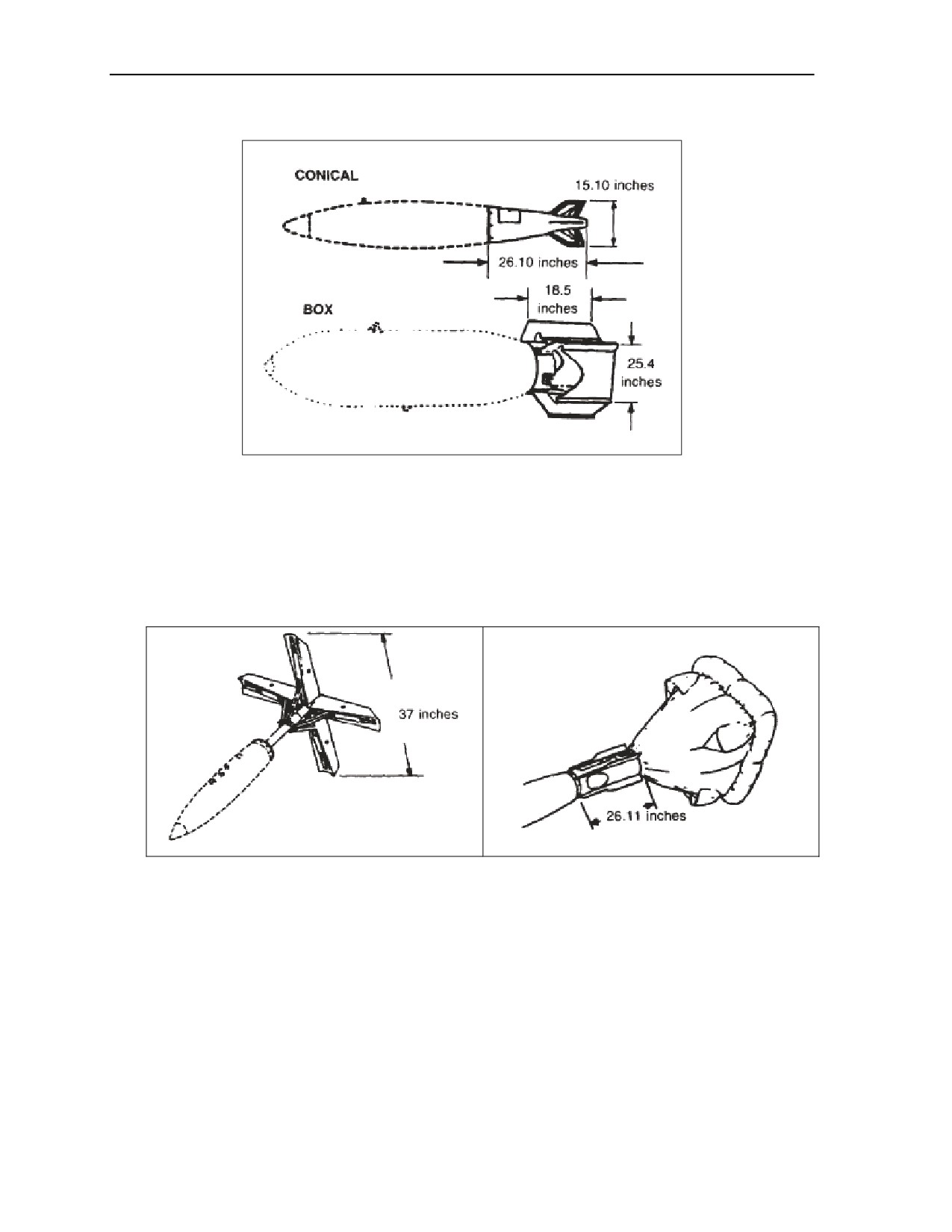
Chapter 2
Figure 2-5. Conical- and box-fin assemblies
2-11.
Some bombs are stabilized by a parachute assembly as shown in Figure 2-7. The parachute assembly
opens after the bomb is released from the aircraft. Even though the parachute may separate from the bomb after it
hits the ground, you should never try to recover a parachute assembly found lying on the ground. The bomb may
have become buried, and the parachute could still be attached to the bomb. As shown in Figure 2-8, former
Soviet Union bombs have fins that are welded to the bomb body. Therefore, the fins cannot become separated
from the bomb. However, the fins can wrap around the rear section of the bomb after it hits the ground and
obscure the tail fuze from view.
Figure 2-6. Retarding-fin assembly (opens
Figure 2-7. Parachute assembly
after release)
2-4
FM 4-30.51
13 July 2006

Recognize UXO
Figure 2-8. Soviet-style fin assemblies
DISPENSERS
2-12. Dispensers may be classified as another type of dropped ordnance. Like bombs, they are carried by
aircraft. Their payload, however, is smaller ordnance called submunitions. Submunitions are discussed later
in this chapter, In Figure 2-9, the cutaway shows the submunitions inside the dispenser body. Dispensers
come in a variety of shapes and sizes depending on the payload inside. Some dispensers are reusable, and
some are one-time-use items.
Figure 2-9. Dispenser (cutaway section)
2-13. Never approach a dispenser or any part of a dispenser you find on the battlefield. The payload of
submunitions may be scattered in the area where the dispenser hit the ground.
13 July 2006
FM 4-30.51
2-5

Chapter 2
DROPPED DISPENSERS
2-14. These dispensers (Figure 2-10) fall away from the aircraft and are stabilized in flight by fin
assemblies. Dropped dispensers may be in one piece or in multiple pieces. All dropped dispensers use
either mechanical time or proximity fuzing. These fuzes allow the payload to be dispersed at a
predetermined height above the target. Multiple-piece dispensers open up and disperse their payload when
the fuze functions. Single-piece dispensers eject their payload out of ports or holes in the body when the
fuze functions.
ATTACHED DISPENSERS
2-15. These dispensers stay attached to the aircraft and can be reloaded and used again. Their payload is
dispersed out of the rear or from the bottom of the dispenser. See Figure 2-11.
Figure 2-10. Dropped dispensers
Figure 2-11. Attached dispensers
SUBMUNITIONS
2-16. Submunitions are classified as either bomblets, grenades, or mines. They are small explosive or
chemical filled items designed for saturation coverage of a large area. They may be antipersonnel (AP),
antimateriel (AMAT), antitank (AT), dual purpose (DP), incendiary, or chemical. Submunitions may be
spread by dispensers, missiles, rockets, or projectiles. Each of these delivery systems disperses its payload
of submunitions while still in flight, and the submunitions drop over the target. On the battlefield,
submunitions are widely used in both offensive and defensive missions.
2-17. Submunitions are used to destroy an enemy in place (impact) or to slow or prevent enemy movement
away from or through an area (area denial). Impact submunitions go off when they hit the ground. Some
area-denial submunitions, including FASCAM, may have a limited active life and self-destruct after their
active life has expired.
2-6
FM 4-30.51
13 July 2006

Recognize UXO
2-18. The major difference between scatterable mines and placed mines is that the scatterable mines land
on the surface and can be seen. Placed mines, discussed in a later section, may be hidden or buried under
the ground and usually cannot be seen.
2-19. The ball-type submunitions shown in Figure 2-12 are AP. They are very small and are delivered on
known concentrations of enemy personnel. The submunition shown in Figure 2-13 is scattered across an
area. Like a land mine, it will not detonate until pressure is put on the submunition.
Figure 2-12. AP ball-type submunitions
Figure 2-13. AP pressure-activated
submunition
WARNING
DO NOT TOUCH OR DISTURB TRIP WIRES ASSOCIATED WITH
AP SUBMUNITIONS.
2-20. The AP submunition shown in Figure 2-14 can be delivered by aircraft or by artillery. When it hits
the ground, a small fragmentation ball shoots up and detonates about 6 feet above the ground. The
submunitions shown in Figure 2-15, are area-denial AP submunitions (FASCAM). These submunitions are
delivered into areas for use as mines. When they hit the ground, trip wires kick out up to 20 feet from the
mine. Most area-denial submunitions use antidisturbance fuzing with self-destruct fuzing as a backup. The
self-destruct time can vary from a couple of hours to as long as several days.
Figure 2-14. AP bounding-fragmentation
Figure 2-15. AP area-denial submunitions
submunition
(FASCAM)
2-21. The DP submunition shown in Figure 2-16 has a shaped charge for penetrating hard targets but is
also used against personnel. These submunitions are delivered by projectiles or rockets. The arming ribbon
serves two purposes: it not only arms the fuze as the submunition comes down, but it also stabilizes the
submunition so that it hits the target straight on.
13 July 2006
FM 4-30.51
2-7

Chapter 2
Figure 2-16. DP submunition
2-22. The AMAT and/or AT submunitions shown in Figure 2-17 are designed to destroy hard targets such
as vehicles and equipment. They are dispersed from an aircraft-dropped dispenser and function when they
hit a target or the ground. Drogue parachutes stabilize these submunitions in flight so they hit their targets
straight on. The submunitions shown in Figure 2-18 are also used to destroy hard targets such as vehicles
and equipment. The only difference is that the fin assembly stabilizes the submunition instead of the drogue
parachute.
Figure 2-17. AMAT/AT parachute-stabilized submunitions
WARNING
DO NOT TOUCH OR DISTURB STABILIZATION PARACHUTE OR
RIBBON THIS MAY ARM OR DETONATE SUBMUNITION.
2-8
FM 4-30.51
13 July 2006

Recognize UXO
Figure 2-18. AMAT/AT fin-stabilized submunitions
2-23. AT area-denial submunitions (Figure 2-19) can be delivered by aircraft, artillery, and even some
engineer vehicles. These FASCAMs may have magnetic fuzing. They will function when they receive a
signal from metallic objects. These submunitions, similar to the AP area-denial submunitions that are
shown in Figure 2-15, also have antidisturbance and self-destruct fuzing. AT and AP area-denial mines are
usually found deployed together.
Figure 2-19. AT area-denial submunitions (FASCAM)
13 July 2006
FM 4-30.51
2-9

Chapter 2
PROJECTED ORDNANCE
2-24. All projected ordnance is fired from some type of launcher or gun tube. Photographs of projected
ordnance and their NEW are in Appendix C. Projected ordnance falls into the following five subgroups:
z
Projectiles.
z
Mortars.
z
Rockets.
z
Guided missiles.
z
Rifle grenades.
PROJECTILES
2-25. Projectiles range from 20 millimeters to 16 inches in diameter and from 2 inches to 4 feet in length.
They can have a variety of fillers including explosives, chemicals (to include riot-control agents such as
combat support [CS]), white phosphorus (WP), illumination flares, or submunitions. Projectile bodies can
be one piece of metal or multiple sections fastened together.
2-26. Projectiles, like bombs, can have impact or proximity fuzing. They can also be fuzed with time-delay
fuzing that functions at a preset time after firing. For safety reasons, all projectiles should be considered as
having proximity fuzing. Getting too close to proximity fuzing will cause the fuze to function, and the
projectile will detonate. Depending on the type of filler and the design of the projectile, the fuze can be in
the nose, as shown in Figure 2-20 or in the base, as shown in Figure 2-21.
2-27. There are two ways projectiles are stabilized, by spin or fin. Spin-stabilized projectiles use rotating
bands near the rear section to stabilize the projectile. See Figure 2-22. Riding along the internal lands and
grooves of the gun tube, these bands create a stabilizing spin as the projectile is fired. Fin-stabilized
projectiles may have either fixed fins or folding fins. See Figure 2-23. Folding fins unfold after the
projectile leaves the gun tube to stabilize the projectile.
Figure 2-20. Nose-fuzed projectiles
2-10
FM 4-30.51
13 July 2006

Recognize UXO
Figure 2-21. Base-fuzed projectile
Figure 2-22. Spin-stabilized projectiles
Figure 2-23. Fin-stabilized projectiles
13 July 2006
FM 4-30.51
2-11
Chapter 2
DEPLETED URANIUM (DU)
2-28. DU ammunition is known to be currently in service with the armed forces of Israel, Russia, UK, and
USA. DU ammunition is commonly restricted to armor piercing fin stabilized discarding sabot (APFSDS)
tank and Armored Fighting Vehicle (AFV) ammunition in calibers ranging from 20 mm to 125mm. Cannon
rounds range from 20 to 30mm for ground attack rotary and fixed wing aircraft.
IDENTIFICATION OF DU UXO
2-29. DU UXOs have the following physical characteristics:
z
They are non-magnetic.
z
DU UXO are extremely heavy. In relation to size DU is 60 percent more dense than lead.
z
They are jet-black in color, possibly with a greenish tinge. After three to four weeks they will
turn green.
z
The fragment will have a honeycombed texture.
z
DU UXOs will retain heat to the point where they will cause serious burns for three to four hours
after firing. A red hot core may be coated with black dust and therefore appear cool.
DANGER
Do not let DU residue or fragments come into contact with
exposed unprotected skin. DU fragments are not to be picked up
by hand; a scoop or other such tool is to be used.
2-30. If you feel you have come in contact with DU you should wash any exposed skin, do not eat or drink
until you have contacted your unit chemical/radiation protection officer.
2-31. You should be aware that it will not be possible, without special instruments, to detect whether a
damaged target has been struck by DU. The following precautions should be taken
z
Do not enter or climb onto a damaged hard target, or loiter within 50 meters, unless you are
working in co-operation with an EOD team.
z
If your work requires you to work within 50 meters, wear a facemask and gloves, and roll your
sleeves down. Cover any cuts and abrasions with waterproof dressings. Spend as little time as
practicable on the task.
z
Do not eat, drink or smoke near the damaged target. After completing your task, wash and
shower as soon as practicable. Remove your outer clothing and, if feasible, replace it. Otherwise,
have it laundered. Do not eat, drink or smoke until you have done so.
z
If you suspect you have been exposed to DU, inform your medical support team.
2-12
FM 4-30.51
13 July 2006
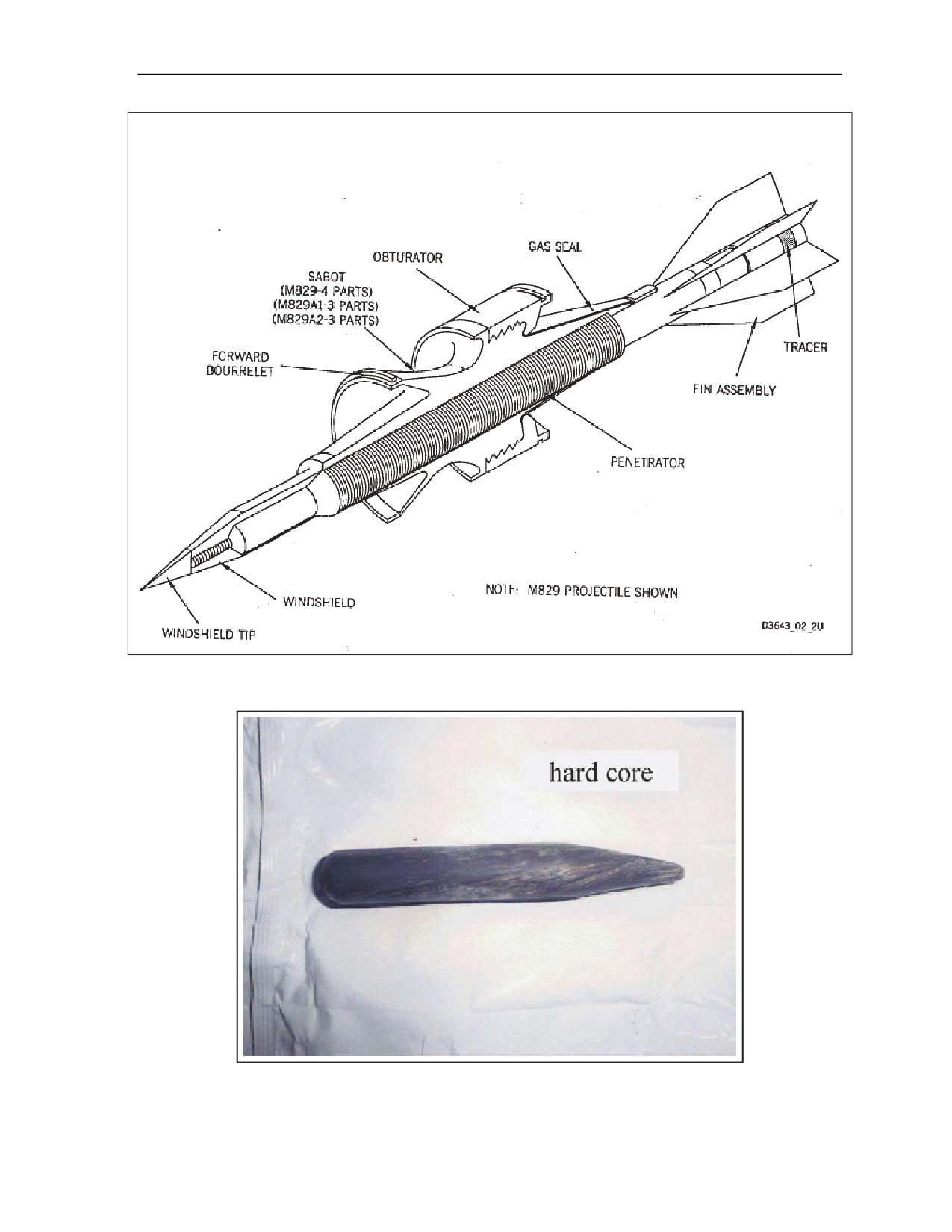
Recognize UXO
Figure 2-24. Line Drawing of a DU Projectile
Figure 2-25. DU UXO
13 July 2006
FM 4-30.51
2-13

Chapter 2
MORTARS
2-32. Mortars range from 45 millimeters to 280 millimeters in diameter. Like projectiles, mortar shells can
be filled with a variety of fillers including explosives, toxic chemicals, WP, or illumination flares. Mortars
generally have thinner metal bodies than projectiles but use the same kind of fuzing. Like projectiles,
mortars are stabilized in flight by fin or spin. Most mortars are fin stabilized, like the ones shown in
Figure 2-26. Other mortars are spin stabilized as shown in Figure 2-27.
Figure 2-26. Fin-stabilized mortars
Figure 2-27. Spin-stabilized mortars
ROCKETS
2-33. A rocket may be defined as a self-propelled projectile. Unlike guided missiles, rockets cannot be
controlled in flight. Rockets range in diameter from 37 millimeters to over 380 millimeters. There is no
standard shape or size to rockets, as you can see in Figure 2-28. All rockets consist of a warhead section, a
motor section, and a fuze. See Figure 2-29. They are stabilized in flight by fins, or canted nozzles, that are
attached to the motor.
2-14
FM 4-30.51
13 July 2006
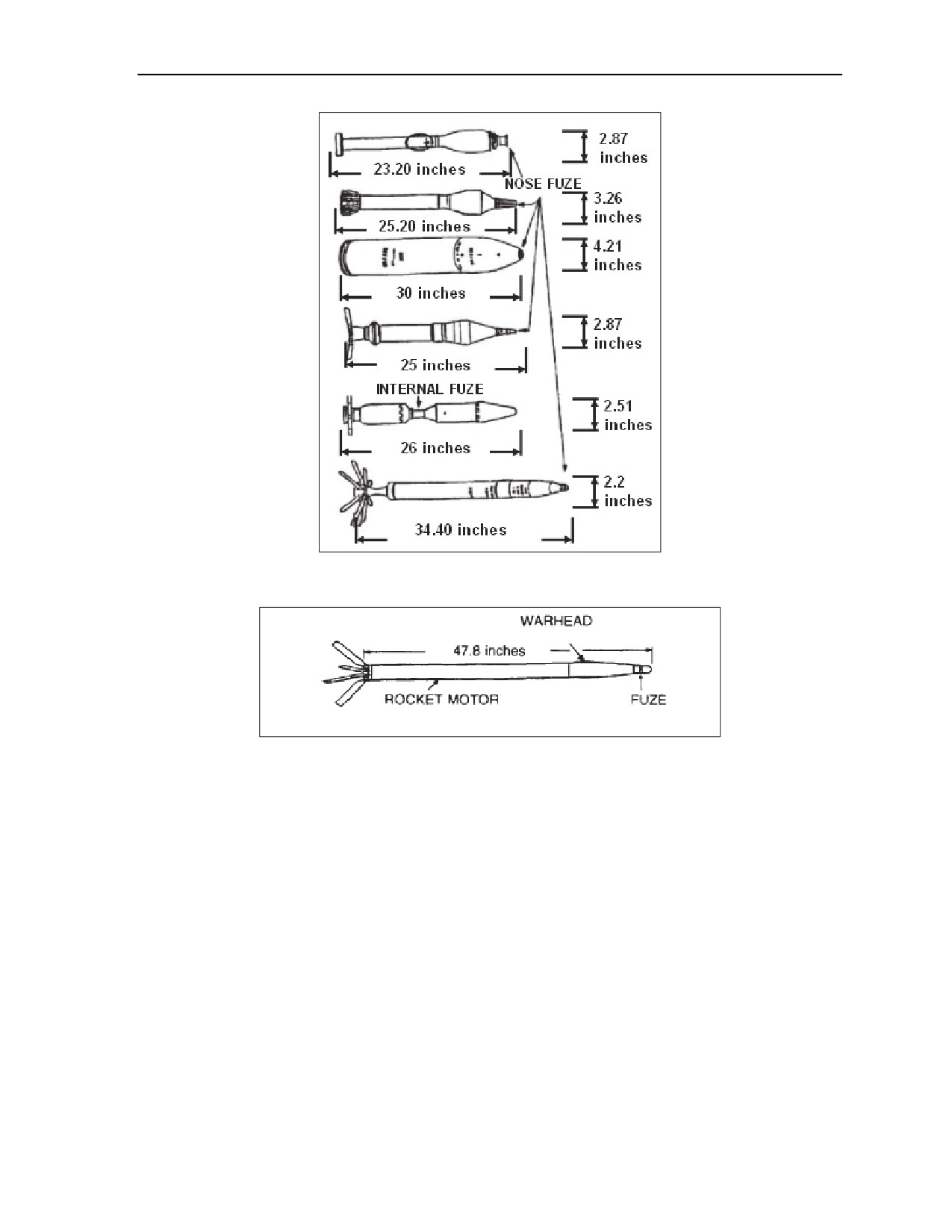
Recognize UXO
Figure 2-28. Rockets
Figure 2-29. Parts of a rocket
2-34. The warhead is the portion of the rocket that produces the desired effect. It can be filled with a
variety of fillers such as explosives, toxic chemicals, WP, submunitions, CS, or illumination flares. The
rocket motor propels the rocket to the target. The fuze is the component that initiates the desired effect at
the desired time. Rockets use the same type of fuzing as projectiles and mortars. The fuze may be located in
the nose or internally between the warhead and the motor.
2-35. Rockets can be launched or fired from individual weapons (such as the light antitank weapon
system), aircraft, mobile-launch vehicles, or stationary launch pads.
2-36. Some rockets are spin stabilized. Unlike projectiles and mortars, these rockets do not have rotating
bands. Instead, as shown in Figure 2-30, their motor nozzles are slanted to produce the spin. The presence
of motor nozzles, or venturis, in the rear of the rocket motor can be used for positive identification purposes
for this type of ordnance.
13 July 2006
FM 4-30.51
2-15

Chapter 2
Figure 2-30. Spin-stabilized rocket
GUIDED MISSILES
2-37. The difference between a missile and a rocket is that the missile is guided to the target by various
guidance systems. Some of the smaller missiles, such as the tube-launched, optically tracked, wire-guided
(TOW) and Dragon missiles are wire-guided by the gunner to their targets. See Figure 2-31. Larger
missiles, such as the phased-array tracking radar intercept on target (PATRIOT) and the Sparrow are
guided by radar to their target. See Figure 2-32. The radar may be internal to the missile, like the
PATRIOT, or external, like the Sparrow, which uses the airplane’s radar system. Guided missiles are
usually stabilized in flight by fins that are controlled by internal electronics. Most guided missiles use
internal, proximity fuzing. Therefore, do not approach any guided missile you find lying on the battlefield.
Figure 2-31. AT guided missiles
2-16
FM 4-30.51
13 July 2006

Recognize UXO
Figure 2-32. PATRIOT and Sparrow guided missiles
RIFLE GRENADES
2-38. Rifle grenades look like mortars and are fired from a rifle that is equipped with a grenade launcher or
an adapter. Many countries use rifle grenades as an infantry direct-fire weapon. Some rifle grenades are
propelled by specially designed blank cartridges, while others are propelled by standard ball cartridges.
Rifle grenades may be filled with high explosives (HEs), WP, CS, illumination flares, or colored screening
smoke. They range in size from the small AP rifle grenade to the larger AT rifle grenade. AP rifle grenades
use impact fuzing. See Figure 2-33. Some rifle grenades, such as the AT, have internal fuzing behind the
warhead (Figure 2-34). This type of fuzing still functions on impact with the target.
Figure 2-33. AP rifle grenades
Figure 2-34. AT rifle grenades
13 July 2006
FM 4-30.51
2-17

Chapter 2
THROWN ORDNANCE
DANGER
Never approach a grenade that was thrown and did not detonate,
even if you threw it. Do not move, jar, or disturb - the fuse may
function at any time.
Never pick up, move, or disturb a found grenade, even if spoon or
safety pin are attached. The grenade may be booby-trapped and
explode when disturbed.
2-39. Thrown ordnance, commonly known as hand grenades, can be classified by use as follows:
z
Fragmentation (also called defensive).
z
Offensive.
z
Antitank.
z
Smoke.
z
Illumination.
Photographs of thrown ordnance and their NEW are in Appendix D.
2-40. Hand grenades are small items that may be held in one hand and thrown. All grenades have three
main parts: a body, a fuze with a pull ring and safety clip assembly, and a filler. See Figure 2-35. Never
pick up a grenade you find on the battlefield, even if the spoon and safety pin are still attached. All
grenades found lying on a battlefield should be considered booby-trapped.
Figure 2-35. Parts of a grenade
FRAGMENTATION GRENADES
2-41. Fragmentation grenades are the most common type of grenade and may be used as offensive or
defensive weapons. See Figure 2-36. They have metal or plastic bodies that hold an explosive filler. These
grenades produce casualties by high-velocity projection of fragments when they detonate. The
fragmentation comes from the metal body or a metal fragmentation sleeve that can be internal or attached
to the outside of the grenade. These grenades may use an impact or burning delay fuze that functions 3 to 5
seconds after the safety lever is released.
2-18
FM 4-30.51
13 July 2006

Recognize UXO
Figure 2-36. Fragmentation grenades
OFFENSIVE GRENADES
2-42. Offensive grenades have a plastic or a cardboard body. See Figure 2-37. They are not designed to
have a lot of fragmentation. Their damage is caused from the over pressure of the explosive blast. These
grenades may use an impact or burning-delay fuze that functions 3 to 5 seconds after the safety lever is
released.
Figure 2-37. Offensive grenade
ANTITANK GRENADES
2-43. AT grenades are designed to be thrown at tanks and other armored vehicles. They have a shaped-
charge explosive warhead and are stabilized in flight by a spring-deployed parachute or a cloth streamer.
See Figure 2-38. These grenades use impact fuzing.
SMOKE GRENADES
2-44. There are two types of smoke grenades: bursting and burning. See Figure 2-39. They may be made of
rubber, metal, or plastic. Bursting-type smoke grenades are filled with WP and detonate when the fuze
functions. These grenades use a burning delay fuze that functions 3 to 5 seconds after the safety lever is
released. Burning-type smoke grenades produce colored smoke. This type of grenade uses an instant-action
fuze. There is no delay once the spoon is released. This is the same type of grenade that is used to dispense
riot-control agents (such as CS).
13 July 2006
FM 4-30.51
2-19

Chapter 2
Figure 2-38. AT grenades
Figure 2-39. Smoke grenades
ILLUMINATION GRENADES
2-45. Illumination grenades are used for illuminating, signaling, and as an incendiary agent. See
Figure 2-40. The metal body breaks apart after the fuze functions and dispenses an illumination flare. This
type of grenade uses a burning-delay fuze that functions 3 to 5 seconds after the safety lever is released.
Figure 2-40. US illumination grenade
2-20
FM 4-30.51
13 July 2006

Recognize UXO
PLACED ORDNANCE
DANGER
Consider all mines to be booby-trapped or to have
antidisturbance fuzing. Never attempt to uncover or remove
placed ordnance.
2-46. Placed ordnance is commonly referred to as land mines. Land mines may be hidden or buried under
the ground and may be classified as AP or AT. Visual detection of land mines may be difficult at best. If
you come to a suspected minefield, report it through your chain of command. For further information and
procedures for reporting land mines, refer to FM 3-34.210. Photographs of placed ordnance and their NEW
are in Appendix E.
ANTIPERSONNEL MINES
2-47. AP mines are generally small and come in different shapes and sizes. See Figure 2-41. AP mines
may be constructed from a variety of materials including plastic and wood. Some AP mines are designed to
function when stepped on, such as those shown in Figure 2-41. Other AP mines are designed for use as
booby traps. See Figure 2-42. These mines are set up to function by using a trip wire laid out across a path
or road. When the trip wire is pulled or cut, the fuze functions. Some AP mines, such as the US claymore
mine, may be set up to function by command detonation.
Figure 2-41. AP pressure-fuzed mines
13 July 2006
FM 4-30.51
2-21