Military reference books and manuals (2009-2023, Volume 2) - page 10
NAVSEA OP 3565/NAVAIR 16-1-529
VOLUME 1 SIXTH REVISION
LIST OF FIGURES
FIGURE
TITLE
PAGE
2-1
RADHAZ Warning Sign Formats
2-4
2-2
Aircraft Radiation Patterns
2-25
A/V-8B HARRIER
2-25
C-2 GRAYHOUND
2-26
C-9B SKYTRAIN
2-27
C-20 GULFSTREAM IV
2-28
C-37 GULFSTREAM V
2-29
C-40A CLIPPER (BOEING 737-700)
2-30
C-130 HERCULES
2-31
KC-130 HERCULES
2-32
E-2C HAWKEYE
2-33
E-6A MERCURY (TACAMO)
2-34
EA-6B PROWLER
2-35
F-14 (ALL MODELS)
2-36
F/A-18 (ALL MODELS)
2-37
P-3C ORION
2-38
P-3C ORION
2-39
P-3C ORION
2-40
S-3B VIKING
2-41
SH-60B SEAHAWK
2-42
T-39N SABERLINER
2-43
UC-12B HURON
2-44
UC-35 CITATION
2-45
V-22 OSPREY
2-46
3-1
Electrical Equivalent of Cargo-Handling Equipment
3-2
4-1
Laser Wavelength Chart
4-2
4-2
Military Laser Exemption Label
4-5
6-1
Effect of Temperature in Generating Hydrocarbon Fuel Flammable Vapors
6-2
6-2
Temperature-Flammability Ranges for Fuels
6-3
6-3
HERF Safe Separation Distance Calculation for MOGAS/AVGAS
(Radar and Communication Systems 225 MHz and Above)
6-6
6-4
HERF Safe Separation Distance Calculation for MOGAS/AVGAS
(Communication Systems Below 225 MHz)
6-7
C-1
Graphic Representation of Permissible Exposure Limits in
Terms of Fields and Power Density for a Controlled Environment
C-6
C-2
Graphic Representation of Permissible Exposure Limits in
Terms of Fields and Power Densityfor an Uncontrolled Environment
C-7
D-1
Calculation of Antenna Illumination Constant
D-6
D-2
Fresnel Region Gain Correction for Uniform Illumination (Rectangular Aperture) . D-8
D-3
Fresnel Region Gain Correction for Cosine Illumination (Rectangular Aperture) ... D-9
iv
NAVSEA OP 3565/NAVAIR 16-1-529
VOLUME 1 SIXTH REVISION
LIST OF FIGURES (CONTINUED)
FIGURE
TITLE
PAGE
D-4
Fresnel Region Gain Correction for Cosine Square
Illumination (Rectangular Aperture)
D-10
D-5
Fresnel Region Gain Correction for Cosine Cubed
Illumination (Rectangular Aperture)
D-11
D-6
Fresnel Region Gain Correction for Cosine Fourth
Illumination (Rectangular Aperture)
D-12
D-7
Normalized On-Axis Power Density Curves
Circular Aperture (1-r2)ρ
D-13
D-8
Sample On-Axis Power Density Computation for a
Rectangular Aperture Antenna (Sheet 1)
D-16
D-8
Sample On-Axis Power Density Computation for a
Rectangular Aperture Antenna (Sheet 2)
D-17
D-9
Sample On-Axis Power Density Computation for a
Circular Aperture Antenna (Sheet 1)
D-18
D-9
Sample On-Axis Power Density Computation for a
Circular Aperture Antenna (Sheet 2)
D-19
D-10
Functions of a Right Triangle
D-21
D-11
Sample Use of Trigonometric Functions for Solving Problems
D-22
D-12
Power Gain Ratio Versus Decibel Gain
D-26
D-13
Power Gain Ratio Versus dBm
D-29
D-14
Example of a Power Density Measurement
D-34
v
NAVSEA OP 3565/NAVAIR 16-1-529
VOLUME 1 SIXTH REVISION
LIST OF TABLES
TABLES
TITLE
PAGE
2-1
Shipboard Communication and Satellite Systems
2-10
2-2
Shore-Based Communication and Satellite Systems
2-14
2-3
Shipboard Radar and Navigation Systems
2-18
2-4
Shore-Based Radar and Navigation Systems
2-21
2-5
Aircraft Radar Systems
2-23
2-6
Aircraft Radiation Patterns
2-24
C-1
PELs for Controlled Environments (Electromagnetic Fields†)
C-2
C-2
PELs for Controlled Environments (Induced and Contact Current)
C-2
C-3
PELs for Uncontrolled Environments (Electromagnetic Fields†)
C-4
C-4
PELs for Uncontrolled Environments (Induced and Contact Current)
C-4
D-1
Rectangular Apertures
D-6
D-2
Circular Apertures with (1-r2)ρ Illumination
D-6
D-3
Circular Aperture Distribution
D-14
D-4
Rectangular Aperture Distribution
D-14
D-5
Decibel Table: Voltage, Current, and Power Ratios
D-25
D-6
dBm Conversion Table
D-30
vi
NAVSEA OP 3565/NAVAIR 16-1-529
VOLUME 1 SIXTH REVISION
SAFETY SUMMARY
Volume 1 of this publication is a safety manual which discusses the hazards of
electromagnetic radiation (RF and laser) to personnel and fuel and approved methods or
procedures for minimizing accidents. Separate warnings or cautions are not contained herein
because the entire content is a warning to the user. However, notes are supplied in the text to
emphasize unusual or special procedures or conditions. Failure to observe operating
procedures and precautions specified in this manual may result in injury to personnel from RF
or laser radiation or the ignition of fuel.
vii/(viii Blank)
This page left intentionally blank
NAVSEA OP 3565/NAVAIR 16-1-529
VOLUME 1 SIXTH REVISION
CHAPTER 1
INTRODUCTION
1-1. PURPOSE AND SCOPE OF MANUAL
1-1.1 This manual consists of two unclassified volumes to provide the data necessary for the
protection of personnel, fuels, and ordnance from radio-frequency (RF) energy (including laser
devices). Volume 1 discusses the Hazards of Electromagnetic Radiation to Personnel (HERP)
and the Hazards of Electromagnetic Radiation to Fuels (HERF) and other flammable materials.
Volume 2 discusses the Hazards of Electromagnetic Radiation to Ordnance (HERO).
1-1.2 Both volume 1 and volume 2 address the standoff distances from shipboard and shore-
based transmitters required to satisfy HERP and HERO (respectively) safety criteria. In
addition, the radiation patterns and safe standoff distances from Navy/Marine Corps aircraft
radars are illustrated
1-1.3 This manual shall be used by the following types of naval activities:
Marine Corps Air Stations
Marine Corps Bases
Naval Air Facilities
Naval Air Stations
Naval Air Warfare Centers
Naval Computer and Telecommunications Facilities
Naval Laboratories
Naval Magazines
Naval Missile Ranges
Naval Ordnance Facilities
Naval Ships
Naval Shipyards
Naval Stations
Naval Surface Warfare Centers
Naval Systems Commands
Naval Weapons Stations
Submarine Support Facilities
1-2. BACKGROUND
1-2.1
RF HAZARDS TO PERSONNEL. Radiation from antennas fed by high-powered RF
transmitters has the potential for injuring personnel present in the vicinity of the radiating
antennas. Transmitters aboard ships, on aircraft, and at shore stations are potential sources of
harmful radiation. At some frequencies, exposure to excessive levels of RF radiation will not
produce a noticeable sensation of pain or discomfort to give warning that injury may be
occurring. Radiated energy can also result in high levels of induced and contact current
1-1
NAVSEA OP 3565/NAVAIR 16-1-529
VOLUME 1 SIXTH REVISION
through the body when in close proximity to high-power RF transmitting antennas below
100 MHz. RF hazards to personnel, permissible exposure limits, and an explanation of induced
and contact currents are contained in chapter 2. RF burns are discussed in chapter 3.
1-2.2
LASER HAZARDS TO PERSONNEL. Laser radiation of high intensity, if absorbed by
the body or eyes, may result in permanent damage. The details for laser operation, safety
precautions, and safe exposure levels are contained in chapter 4.
1-2.3
IONIZING RADIATION. Ionizing radiation sources, hazard levels, and safety
precautions are discussed in chapter 5.
1-2.4
RF HAZARDS TO FUEL. Study and research are continuing to (1) provide safe
handling distances for fuel and (2) eliminate conditions conducive to arcing during fuel handling.
Procedures to reduce the possibility of fuels being ignited by RF radiation-induced arcing are
provided in chapter 6.
1-2.5
RF HAZARDS TO ORDNANCE. Electroexplosive devices, electrically initiated
devices, and ordnance electrical systems may be affected when exposed to RF energy. The
Naval Sea Systems Command (NAVSEA) Program Executive Office sponsors testing programs
to determine weapon susceptibility to RF energy. Tests are conducted in the maximum RF
environments to which ordnance items may be exposed during a typical stockpile-to-launch
scenario. An affected system or item might have sufficient current induced by the RF field to
result in premature firing, explosion, or dudding. A listing of all Navy and Marine Corps
ordnance with HERO concerns is contained in Volume 2.
1-3. RESPONSIBILITIES
1-3.1
NAVAL SEA SYSTEMS COMMAND. NAVSEA, in accordance with Chief of Naval
Operations directives, exercises technical direction over fleet personnel safety and is
responsible for shipboard HERP- and HERF-related data and issues. As part of NAVSEA,
Naval Ordnance Safety and Security Activity, N716, is responsible for all HERO-related data
and safety of ammunition, explosives, and other hazardous materials in the fleet and shore
establishments.
1-3.2
SPACE AND NAVAL WARFARE SYSTEMS COMMAND (SPAWAR). SPAWAR is
responsible for shore facility HERP- and HERF-related data and issues.
1-3.3
BUREAU OF MEDICINE AND SURGERY (BUMED). BUMED is responsible for
adopting scientifically established personnel exposure levels for electromagnetic and laser
radiation, reviewing personnel overexposures, and providing appropriate medical
recommendations.
1-3.4
COMMANDING OFFICER. In addition to the duties and responsibilities inherent in the
position of commanding officer as set forth in Navy regulations or as promulgated by higher
authority, the commanding officer of a ship or naval shore station is solely responsible for the
safety of his/her command. He/she must take the same active, aggressive leadership in safety
1-2
NAVSEA OP 3565/NAVAIR 16-1-529
VOLUME 1 SIXTH REVISION
that he/she takes in other phases of command responsibility. It is the commanding officer’s
responsibility to require personnel of other agencies, including contractors, while on board ship
or at a facility under his/her command, to conduct their activities in accordance with established
safety rules. The commanding officer shall enforce the mandatory requirements of this manual
and shall initiate those directives and inspections necessary to evaluate compliance with the
rules and regulations prescribed herein. The absence of a safety requirement in this manual, or
in the documents referenced herein, does not necessarily indicate that safeguards are not
required. Commanding officers have the authority to impose and enforce more stringent safety
rules than those imposed by higher authority. Where no existing safety rule or regulation
applies, or where a deviation from an established mandatory safety regulation is desired, the
commanding officer shall submit to Commander, NAVSEA, Code 53H, full particulars and
detailed plans for approval. In the interim, the commanding officer shall take the necessary
action to control the hazard. Shipboard commanders may waive compliance with any provision
of this manual when essential under emergency conditions.
1-3.5
SHIP AND SHORE SUPERVISORY PERSONNEL. Supervisors shall be thoroughly
familiar with the provisions of this publication. Supervisors have no authority to waive or alter
NAVSEA and station safety regulations, nor shall they permit the violation of such safety
regulations by others. They shall act positively to eliminate any potential accident hazards
existing in operations under their jurisdiction. Aboard ship, supervisory personnel must perform
the functions of shore station safety directors. Each supervisor shall also comply with the
following regulations:
a. Explain to all personnel under his/her immediate supervision the standard safety
regulations, industrial hygiene safeguards, and precautions that they must follow and enforce
regarding the observance of all safety regulations by personnel. The supervisor shall explain
the safe distances as they apply to RF energy and lasers.
b. Instruct and train personnel under his/her immediate supervision in the work that they
are to perform, whether instruction is given directly or through experienced operators, until the
supervisor is satisfied that all personnel are capable of performing the work safely. This
instruction shall also encompass complete information concerning transmitter location,
identification, adherence to all RF and laser warning signs and placards, and observance of all
safety circles and other safety zones.
c. Ensure that personnel are qualified and certified to perform the job assigned and that
such certification is current. Report promptly to his/her immediate superior all personnel who, in
his/her opinion, are not qualified for their assigned work.
d. Investigate or assist in the investigation of all accidents involving operations,
equipment, or personnel under his/her supervision, and report or assist in the preparation of the
report on the investigation’s results to higher authority for appropriate action.
e. Identify all persons entering or approaching a radiation hazards (RADHAZ) area in
his/her charge, and determine their authority to enter and/or remain in the area. Exercise his/
1-3
NAVSEA OP 3565/NAVAIR 16-1-529
VOLUME 1 SIXTH REVISION
her authority to eject any person whose presence and/or actions, in his/her opinion, are
detrimental to safety.
f. Forbid any major repairs or modification to any transmitting equipment except in
accordance with specific instructions of the commanding officer. Enforce the safety
requirements in his/her area.
g. Ascertain that all conditions in the area under his/her jurisdiction comply with orders
relating to operation shutdown. When the operation is not relieved by an incoming shift, the
supervisor shall make certain that all transmitters are shut off. When an incoming shift relieves
his/her operation or he/she is relieved for any reason, the supervisor shall make a complete
report to the relief of any situation that requires immediate attention or which should be kept
under observation.
h. Enforce observance of the safety regulations concerning personnel protective
clothing and equipment.
i.
Report in writing to his/her commanding officer any requests, suggestions, and
comments he/she may have with regard to safety standards.
1-3.6
SHIP AND SHORE OPERATING PERSONNEL. Operating personnel are responsible
for understanding and strictly observing all safety standards, requirements, and precautions
applicable to their work or duty. In addition, each individual will:
a. Report to his/her supervisor any unsafe condition, personnel actions, or any
equipment or material that he/she considers unsafe.
b. Warn others whom he/she believes to be endangered by known hazards or by failure
to observe safety precautions.
c. Wear or use approved protective clothing or equipment when required.
d. Report to his/her supervisor any injury or evidence of impaired health to himself/
herself or others occurring in the course of work or duty.
e. Be prepared, in the event of an unforeseen hazardous occurrence, to give an audible
warning to the other employees and to exercise such reasonable caution as is appropriate to
the situation.
f. Report the presence of unauthorized personnel in the work area to his/her supervisor.
1-4. PERSONNEL TRAINING
1-4.1 All personnel engaged in operations involving the use of RF transmitting equipment or
laser devices shall be familiar with all phases of work which they will be required to perform.
Included in their training will be instruction in the following:
1-4
NAVSEA OP 3565/NAVAIR 16-1-529
VOLUME 1 SIXTH REVISION
a. RF and laser radiation hazards.
b. Sources of RF burns.
c. Detection of faulty transmitters or related equipments.
d. RADHAZ warning signs, devices, and controls.
e. Electrical characteristics of metallic objects.
f. Sources of RF hazards.
g. The characteristics of modified or new RF transmitting equipment.
h. Use of protective equipment.
i.
Use of OPNAVINST 5100.23 (series), OPNAVINST 5100.19 (series), and this
manual.
1-4.2 Films dealing with RF hazards are available for training purposes through regular
channels. Film identification number for the series titled "Radio Frequency Radiation Hazards"
is MN9682. Individual films in this series are as follows:
a. MN9682a - Radio Frequency Radiation Hazards - RF Hazards and Personnel Safety.
b. MN9682d - Radio Frequency Radiation Hazards - RF Burns, Causes and Effects.
1-5. PRECAUTIONS TO ENSURE THE SAFETY OF PERSONNEL
It is the responsibility of the commanding officer of each ship or shore station to
implement the requirements contained in this manual, including the following:
a. Ensure that procedures are established whereby RF transmitting equipment is
positively controlled and coordinated with personnel working near antennas, handling
ordnance, and conducting fueling operations. Procedures for controlling laser operations also
shall be generated.
b. Ensure that RF hazards associated with the operation of laser and radar transmitters
(in both controlled and uncontrolled environments) are known to all personnel, and that the
necessary safety precautions are implemented. See paragraph 2-2.1.2, for the definition of
controlled and uncontrolled environments.
c. Have RF RADHAZ surveys conducted to determine the appropriate safety
precautions for personnel and for operations involving fuel and ordnance. Requests for RF
hazard surveys and information relating to shipboard HERP and HERO, or shore facility HERO,
should be mailed to Commander, Dahlgren Division, Naval Surface Warfare Center,
1-5
NAVSEA OP 3565/NAVAIR 16-1-529
VOLUME 1 SIXTH REVISION
J52/R. Needy, 17320 Dahlgren Road, Dahlgren, VA 22448-5100, or forwarded electronically to
needyri@nswc.navy.mil. Requests may also be made by calling (540) 653-3446/8594 or DSN
249-3446/8594.
Requests for RF hazard surveys or information relating to shore facility HERP should be
mailed to Space and Naval Warfare Systems Command, Code 323/W. Hammer, P.O. Box
19022, North Charleston, SC 29419-9022, or forwarded electronically to
hammerw@spawar.navy.mil. Requests may also be made by calling (843) 218-4876.
Requests for laser system evaluations or range surveys should be submitted as
described in paragraph 4-8, of this document.
d. Ensure that HERP, HERF, HERO, and laser considerations are included in all
proposed changes to station or facility operations.
1-6. RADIO FREQUENCY AND LASER OVEREXPOSURE REPORTING REQUIREMENTS
Report all RF overexposure incidents in accordance with the requirements of
OPNAVINST 5100.19 (series) for ship personnel and OPNAVINST 5100.23 (series) for shore
personnel. Report laser overexposure incidents as per OPNAVINST 5100.27/MCO 5104.1
(series) and BUMEDINST 6470.23 (series).
1-7. DEFINITIONS AND ABBREVIATIONS
The definitions of the terms and the meaning of the abbreviations used are listed in
appendix A.
1-8. REFERENCE DOCUMENTS
A list of reference documents applicable to this volume is presented in appendix B.
These documents, together with ship and station instructions and notices, technical
publications, and standard operating procedures shall be maintained in appropriate libraries.
These documents are essential for complete understanding of the safety regulations contained
herein.
1-9. BIOLOGICAL EFFECTS OF ELECTROMAGNETIC RADIATION (EMR) AND SAFE
EXPOSURE LIMITS
Appendix C describes the biological effects of EMR on the human body and the limits to
which the body can be safely exposed.
1-10. CALCULATIONS AND MEASUREMENTS OF ELECTROMAGNETIC FIELDS
The electromagnetic environment, the method for calculating power density in an
electromagnetic field, and calculation aids for use in predicting RF radiation hazards are
described in appendix D.
1-6

NAVSEA OP 3565/NAVAIR 16-1-529
VOLUME 1 SIXTH REVISION
1-11. REPORTING OMISSIONS/ERRORS IN MANUAL
Ships, training activities, supply points, depots, Naval shipyards, and supervisors of
shipbuilding are requested to arrange for the maximum practical use and evaluation of NAVSEA
technical manuals. All errors, omissions, discrepancies, and suggestions for improvement to
NAVSEA technical manuals shall be reported to the Commander, Naval Surface Warfare
Center, Port Hueneme Division (NSWC/PHD) (Code 5E31), 4363 Missile Way, Port Hueneme,
CA 93043-4307 on NAVSEA Technical Manual Deficiency/Evaluation Report (TMDER),
NAVSEA Form 4160/1. A copy of NAVSEA TMDER Form 4160/1 is included at the end of this
publication. For activities with internet access, this form may also be completed and processed
using NSWC/PHD website: http://nsdsa.phdnswc.navy.mil. All feedback comments shall be
thoroughly investigated and originators will be advised of TMDER resolution. If you prefer to
submit a TMDER using a word file, click here
TMDER
1-7/(1-8 Blank)
This page left intentionally blank
NAVSEA OP 3565/NAVAIR 16-1-529
VOLUME 1 SIXTH REVISION
CHAPTER 2
HAZARDS OF ELECTROMAGNETIC RADIATION TO PERSONNEL
2-1. INTRODUCTION
2-1.1 GENERAL. This chapter discusses the hazards of electromagnetic radiation to
personnel (HERP), as well as the means by which such radio-frequency (RF) hazards may be
mitigated. Electromagnetic radiation (EMR), as discussed in this section, is referred to as
nonionizing radiation, a form of radiation that does not have sufficient energy to cause ionization
of atoms or molecules. Electromagnetic emissions from laser, radar, communication, and
microwave sources are examples of nonionizing radiation.
Also included in this chapter is a list of personnel safe distances associated with
currently operational Navy aircraft, as well as shipboard and shore-based RF transmitters. In
the case of aircraft, the radiation pattern of the installed radar system is also provided. The
biological hazards associated with electromagnetic (RF) radiation [as established by the
Institute of Electrical and Electronics Engineers (IEEE) C95.1 Standards Committee, adopted
by the Tri-Service Electromagnetic Radiation Panel, and presented in Department of Defense
Instruction (DODINST) 6055.11] are discussed in appendix C. As technical agent for Naval Sea
Systems Command (NAVSEA), Naval Surface Warfare Center, Dahlgren Division, Dahlgren,
Virginia, is responsible for identifying potentially hazardous shipboard areas. Space and Naval
Warfare Systems Command (SPAWAR), Charleston, South Carolina, is responsible for
identifying potential hazardous shore facility areas and for ensuring that controls necessary to
prevent biological injury to personnel are defined and implemented.
2-1.2 BACKGROUND. Radar and communication systems which use high-power RF
transmitters and high-gain antennas represent a biological hazard to personnel working on, or
in the vicinity of, these systems. The detrimental effects of overexposure to EMR are
associated with an increase in overall body temperature or a temperature rise in specific organs
of the body.
2-2. EMR HAZARDS TO PERSONNEL
2-2.1 PERMISSIBLE EXPOSURE LIMITS (PELS).
2-2.1.1 DODINST 6055.11 lists safe limits based upon established biological effects due to RF
radiation (RFR) exposure over the frequency range of 3 kHz to 300 GHz. The biological effects
have been determined to be a function of the specific absorption rate (SAR), which is frequency
dependent and averaged over a 6-minute time period. A more detailed discussion of PELs and
SARs is presented in appendix C.
2-1
NAVSEA OP 3565/NAVAIR 16-1-529
VOLUME 1 SIXTH REVISION
2-2.1.2 Exposure limits are specified for locations that are defined as either controlled or
uncontrolled environments. Controlled environments are areas (designated shipboard work/
equipment spaces, shipboard weather decks, and topside areas) where exposure to higher-
than-normal levels of electromagnetic energy may be incurred by personnel who are aware of
the potential for such exposure. Uncontrolled environments include public areas, living
quarters, and work spaces where there is no expectation that higher electromagnetic
environments should be encountered. Shore facilities will typically have a combination of
controlled and uncontrolled environments, as defined by each command. A more detailed
discussion of exposure limit guidelines is provided in appendix C. However, since these
guidelines require further explanation and are subject to change, DODINST 6055.11 (series)
should be consulted by persons responsible for conducting RF hazard analyses.
2-2.1.3 The exposure limits for controlled environments represent scientifically derived values
to limit absorption of electromagnetic energy in the body and to restrict the magnitude of
currents induced in the body. As a result, the amount of RF energy absorbed is insufficient to
produce or cause any adverse health effects, even under repeated or long-term exposure
conditions. The controlled environmental limits are the equivalent of personnel exposure
standards for all individuals. In uncontrolled environments where access is not restricted or
controlled, lower permissible RF exposure levels have been adopted. The reduced exposure
limits permitted in uncontrolled environments reflect a consensus to minimize exposure levels
outside well-defined areas and should not be interpreted as a disregard for any known adverse
health risk. There are no shipboard topside environments defined as uncontrolled
environments; therefore, this condition/situation is not discussed in detail in this report. For
shore facilities, uncontrolled areas are determined by the local command authority.
2-2.1.4 In those cases where personnel in a controlled environment must be exposed to power
densities greater than the continuous PEL, the use of time averaging may be employed to
determine the safe stay-time. Intermittent (vice continuous) exposure times can be calculated
as described in paragraph C-5 and in DODINST 6055.11.
2-2.1.5 Induced and Contact Currents. Induced and contact current exposure limit guidelines
for controlled and uncontrolled environments are provided in tables C-2 and C-4, respectively.
However, since these guidelines require further explanation and are subject to change,
DODINST 6055.11 should be consulted by persons responsible for conducting hazard
assessments.
2-2.1.6 Induced Current PEL. When a person is freely standing (not grasping a conductive
object) in a radiated field, RF currents are induced into the body. As those induced currents
flow between the human body and ground, heat is produced, particularly in the constricted area
of the ankles. For frequencies between 100 kHz and 100 MHz, current induced through the feet
in a controlled environment is limited to 100 mA if measured through one foot, or 200 mA if
measured through both feet. The 200-mA limit through both feet assures that localized SARs
will not exceed the 20-W/kg limit for extremities.
2-2.1.7 Contact Current PEL. Contact current, or "grasping contact" current, is the current
which flows through the hand(s) when a person grasps a conductive object while in a radiated
2-2
NAVSEA OP 3565/NAVAIR 16-1-529
VOLUME 1 SIXTH REVISION
field. The contact current (PEL) in a controlled environment is 100 mA for the hand in contact
with the ungrounded surface. This limit provides assurance that the 20-W/kg extremities limit
will not be exceeded.
The present procedure for measuring this limit of contact or "grasping contact" current for
the shipboard and shore radiation hazards (RADHAZ) survey is to measure only those items
which are grasped during their normal operation or use, such as life lines or rails. Currently, a
Type 3 RADHAZ warning sign (RF Burn) is posted in the vicinity of these items to denote a
contact-current hazard. For items which are grasped during normal operations (e.g., signal
lights), Type 5 warning signs are used to provide specific control measures. RADHAZ warning
sign formats are shown in figure 2-1.
2-2.1.8 RF Burn Criteria. The nature of RF burns, how they occur, and procedures for
minimizing their effects are contained in chapter 3 of this document, from which the following
excerpt is extracted:
An RF burn is the result of RF current flow through that portion of the body in direct contact
with a conductive object (in which an RF voltage has been induced) or at the site of a spark
discharge (no direct contact with a conductive object). Any burn injury that occurs is entirely
the result of heat produced by current flow through the resistance of the skin. Current flow
through a resistance produces heat regardless of the nature of the circuit.
As discussed in chapter 3, the established criteria is that an open-circuit voltage
exceeding 140 volts on an item in an RFR field is to be considered potentially hazardous. The
effect of the heat on a person ranges from warmth to painful burns. However, field tests have
shown that, because of the many variables involved, it is not uncommon to encounter
significantly higher voltages that will not cause an RF burn. The term "hazard" can range from
visible skin damage to a shock sensation. The specific level at which contact with RF voltages
should be classified an RF burn hazard is not a distinct one; however, 140 volts is recognized
as the PEL, and a Type 3 RADHAZ warning sign (RF Burn) is posted in the vicinity of these
items to denote an RF burn hazard. RADHAZ warning sign formats are shown in figure 2-1.
2-2.1.9 NAVSEA, Code 53H, is responsible for determining hazardous shipboard areas and
ensuring that the possibility of biological injury to personnel from RF radiation is minimized or
eliminated. Theoretical calculations and RF field-intensity and power-density measurements
are used to establish the safe distances from radar antennas. This information is then used to
determine whether or not hazardous shipboard areas exist. Radiation inhibit zones are used to
minimize the number of hazardous areas. Appropriate warning signs, warning instructions,
and/or markings shall be posted in all hazardous areas subject to entry by personnel.
2-2.1.10 For shipboard situations, weather decks, enclosed and open masts, and electronic
work spaces (at a minimum) should be considered controlled environments. For shore stations,
accessible areas beyond the stations’ perimeter fence lines (at a minimum) should be
considered uncontrolled environments.
2-3

NAVSEA OP 3565/NAVAIR 16-1-529
VOLUME 1 SIXTH REVISION
FIGURE 2-1. RADHAZ Warning Sign Formats
2-4
NAVSEA OP 3565/NAVAIR 16-1-529
VOLUME 1 SIXTH REVISION
2-2.1.11 No special RF exposure limits or additional RF exposure restrictions are imposed in
the case of pregnancy.
2-2.2 WARNING SIGNS, DEVICES, AND CONTROLS.
2-2.2.1 RADHAZ Warning Signs. RADHAZ warning signs have been developed to advise
personnel of the hazards of EMR. The format of these signs conforms with national and
international standards. The RADHAZ warning sign formats are provided, along with the
National Stock Numbers, in figure 2-1.
2-2.2.2 Variations, to include subdued signs for camouflage or tactical reasons, or to provide
improved visibility under certain lighting conditions, are authorized, provided the general layout
of the sign remains the same.
2-2.2.3 When required by military operational considerations, commanders may waive the
requirement for signs, provided personnel are informed of possible hazards by other means.
2-2.2.4 Type 1 Warning Sign. The Type 1 warning sign advises personnel of an RF hazard
and shall be posted at the boundary (PEL line) of an area, beyond which the PEL may be
exceeded (see paragraph 2-2.2.9). Personnel may pass through this area but must not linger.
If personnel are required to remain in the area, they must contact the cognizant command
authority, who will ensure that procedures are implemented to limit RF exposure to a level
below PEL. Type 1 warning signs shall never be posted in an area undefined by a PEL line.
2-2.2.5 Type 2 Warning Sign. The Type 2 warning sign excludes personnel from proceeding
past a designated point. The sign informs personnel to check with command authority before
proceeding beyond this point. This sign is normally posted at access points to RADHAZ
restricted zones, such as masts and high-power antenna platforms, and in the vicinity of
normally occupied areas which have RADHAZ barriers or personnel barriers to restrict access.
2-2.2.6 Type 3 Warning Sign. The Type 3 warning sign informs personnel that contact current
and/or RF burn hazards may exist on metallic objects in this area. The Type 3 sign is used to
denote RF hazards due to contact with metallic objects in the area and is normally posted on
the metallic object that presents the worst hazard. Personnel should be aware that this hazard
may also exist on other metallic objects in the area. An RF burn hazard may exist when either
the RF voltage or contact current PEL is exceeded. Additional RADHAZ control measures (i.e.,
Type 5 RADHAZ sign) may be required to ensure that this hazard is limited to levels that do not
exceed the PEL on metallic objects that personnel must grasp, such as signal lights and
binoculars.
2-2.2.7 Type 4 Warning Sign. The Type 4 warning sign informs personnel that an RF hazard
exists and to check with command authority prior to fueling operations. Further instructions are
then provided that may include limitation on transmitter power or silence of specific transmitting
antennas. This sign is usually placed next to a fuel storage and/or refueling station.
2-5
NAVSEA OP 3565/NAVAIR 16-1-529
VOLUME 1 SIXTH REVISION
2-2.2.8 Type 5 Warning Sign. The Type 5 warning sign provides a blank area in which special
instructions necessary for safe operations can be specified. Often, the sign provides operators
and maintenance personnel with specific frequency and/or power limitation information for the
safe operation of the antenna systems associated with the RF transmitting equipment. The
Type 5 sign may also be used to inform personnel to contact command authority prior to
operation of equipment in order to prevent an RF hazard to the operator or other personnel.
The Type 5 sign should be posted in clear view of system operators.
2-2.2.9 PEL Line. A PEL line is used to mark a deck area where precautionary measures are
required to minimize the possibility of personnel exposure to RFR in excess of the PEL. The
PEL line is a 4-inch-wide red line (usually a circle or semicircle) painted on the deck to mark the
boundary of an area surrounding an antenna where the PEL can be exceeded. When a PEL
line is used, a Type 1 RADHAZ warning sign is posted on the PEL line to advise personnel that
a hazard may exist and that they must keep moving. Personnel outside the PEL line need not
take precautionary measures; however, when it is necessary for personnel to be within the
marked areas, they must contact appropriate personnel who will ensure that operational
procedures are implemented to limit RF exposure to a level below the PEL.
2-2.2.10 Red Warning Bands. A red warning band is used to mark a safety rail or life rail
where precautionary measures are required in order to minimize the possibility of exposure to
contact currents in excess of the PEL. The red warning band is a 4-inch-wide red line painted
on the top of the safety rail to mark the boundary of an area in proximity to an antenna where
the PEL can be exceeded. Where a red warning band is used, a Type 3 RADHAZ warning sign
is posted to advise personnel that an RF burn hazard may exist. In those cases where further
information or clarification is required, a Type 5 RADHAZ sign should be used.
2-2.2.11 Personnel Barriers. In areas where access to levels greater than 10 times the
exposure limits for controlled environments may exist, warning signs alone do not provide
sufficient protection. Devices such as flashing lights, audible signals, barriers, and/or interlocks
shall be installed to prevent inadvertent access. The specific device(s) employed will be
determined by the certifying authority based on the potential for exposure.
Personnel barriers are devices that restrict personnel access to an antenna or area
where the PEL can be exceeded. The personnel barrier may be a fixed one, such as a
permanent fenced area around an antenna. If no access to the antenna is provided, personnel
barriers are not required. If there is an access opening, a temporary barrier (i.e., nylon rope)
may be used to restrict personnel access. In this case, a Type 2 warning sign is also posted on
a placard, which is normally attached to the nylon rope.
2-2.2.12 Frequency and/or Power Management. Frequency and/or power management
restrictions may be employed to ensure that personnel are not exposed to RF energy in excess
of the authorized PEL. Such restrictions may be imposed to limit RF exposure within a
RADHAZ area defined by PEL lines, or to limit RF contact current on items that personnel are
required to grasp while performing their assigned task. The HERP/Hazards of Electromagnetic
Radiation to Fuel (HERF) Technical Report (prepared following a HERP/HERF survey) provides
2-6
NAVSEA OP 3565/NAVAIR 16-1-529
VOLUME 1 SIXTH REVISION
specific guidance and recommended operating procedures to manage potential RF hazards.
These procedures may include one or more of the following:
a. Refrain from using the antenna.
b. Reduce power for the frequencies at which the PEL is exceeded.
c.
Refrain from using frequencies at which the PEL is exceeded.
Type 5 warning signs are used to provide operator or maintenance personnel with the
frequency and/or power management requirements.
2-2.3 CALCULATED HERP STANDOFF DISTANCES. The HERP standoff distances listed in
table 2-1 and table 2-4 are considered to be those distances from a transmitting antenna where
the radiated field intensity is equal to the continuous exposure (whole body) PEL for controlled
environments specified in DODINST 6055.11 (series). The standoff distances were calculated
using power density modeling programs developed by NAVSEA and based upon currently
available system electrical specifications. In most cases, these calculated distances are based
upon worst-case conditions as no system installation losses were considered.
NOTE
While phased-array antenna systems do not physically rotate, their moving
beam characteristics are equivalent to rotating-beam systems.
2-2.3.1 The HERP standoff distances noted in tables 2-1 through 2-4 are based on the
assumption that the specified system uses a fixed (nonrotating) antenna. However, with the
exception of communication systems (i.e., HF, VHF, UHF, and satellite systems), most
shipboard and land-based radar systems use rotating-beam antennas. Typically, there will be
no HERP concerns (hazards) associated with rotating-beam systems, since the intermittent
exposure time per radar sweep will result in exposures which do not exceed the continuous-
exposure PEL. However, since rotating-beam systems may be operated in a fixed mode during
certain evolutions, it is essential that personnel be aware of the potential hazards associated
with this mode of operation.
2-2.4 RADIO FREQUENCY EQUIPMENT HAZARDS.
2-2.4.1 Tables 2-1 through 2-5 list the most common shipboard, shore-based, and aircraft RF
transmitters capable of producing potentially harmful levels of EMR. The HERP standoff
distances specified in these tables are based on the PELs for controlled environments that
appear in appendix C. The information was modified (where noted) by actual measurements
obtained during shipboard or shore-station RF surveys. Requests for assistance in making
such measurements for ship equipment should be directed to Commander, Dahlgren Division,
Naval Surface Warfare Center, J52/R. Needy, 17320 Dahlgren Road, Dahlgren, VA
22448-5100, (540) 653-3446/8594 or DSN 249-3446, or forwarded electronically to
needyri@nswc.navy.mil. Requests pertaining to shore-based equipment should be directed to
2-7
NAVSEA OP 3565/NAVAIR 16-1-529
VOLUME 1 SIXTH REVISION
Space and Naval Warfare Systems Command, Code 323/W. Hammer, P.O. Box 19022,
Charleston, SC 29419-9022, (843) 218-4876 or DSN 588-4876, or forwarded electronically to
hammerw@spawar.navy.mil.
2-2.4.2 Before personnel are exposed to RF energy from radar and/or communication
equipment not listed in tables 2-1 through 2-5, the HERP safe standoff distance shall be
determined. This information is normally contained in the command’s HERP survey.
The HERP certification survey for modified or newly installed shipboard equipment shall
be obtained by contacting Commander, Dahlgren Division, Naval Surface Warfare Center, J52/
R. Needy, 17320 Dahlgren Road, Dahlgren, VA 22448-5100, (540) 653-3446/8594 or DSN
249-3446, or via e-mail (needyri@nswc.navy.mil). For information pertaining to shore-based
equipment, contact Space and Naval Warfare Systems Command, Code 323/W. Hammer, P.O.
Box 19022, Charleston, SC 29419-9022, (843) 218-4876 or DSN 588-4876, or via e-mail
(hammerw@spawar.navy.mil).
2-2.4.3 Operational and/or maintenance requirements that expose personnel to RF
environments in excess of the (controlled environment) PELs appearing in appendix C may be
permitted using time-averaging (vice continuous-exposure) criteria. Because of the complexity
of this calculation, the recommended procedure for shipboard equipment is to contact
Commander, Dahlgren Division, Naval Surface Warfare Center, J52/R. Needy, 17320 Dahlgren
Road, Dahlgren, VA 22448-5100, (540) 653-3446/8594 or DSN 249-3446, or via e-mail
(needyri@nswc.navy.mil). For information pertaining to shore-based equipment, contact Space
and Naval Warfare Systems Command, Code 323/W. Hammer, P.O. Box 19022, Charleston,
SC 29419-9022, (843) 218-4876 or DSN 588-4876, or via e-mail (hammerw@spawar.navy.mil).
2-2.5 AIRCRAFT RADAR HAZARDS.
2-2.5.1 Table 2-5 lists the PEL and HERP fixed-beam standoff distances associated with the
aircraft radar systems specified. Figure 2-2 depicts the radiation patterns and HERP safe
separation distances associated with these systems. Many of the listed aircraft are equipped
with landing-gear interlock (weight-on-wheels) switches which make it impossible to energize
the radar transmitter until one or more deliberate actions have been taken. All personnel who
operate or work in the vicinity of aircraft radar transmitters on deck shall be familiar with the
RADHAZ zones around the aircraft. Maintenance personnel who bypass such safety interlocks
shall ensure that safety zones are established and that personnel are alerted to the potential
hazard. Maintenance personnel shall also ensure that interlock bypass switches are returned
to their normal positions at the completion of maintenance.
2-2.5.2 Unlike most shipboard and land-based systems, aircraft radars do not typically rotate.
Rather, such systems scan (sweep) the airspace to the left and right of the aircraft centerline. In
most cases, the scan can be narrowed by the operator to just a few degrees either side of
center. Therefore, for airborne radars, the HERP fixed-beam standoff distance and scan limits
specified in table 2-5 and figure 2-2 should always be maintained during ground radar
operation.
2-8
NAVSEA OP 3565/NAVAIR 16-1-529
VOLUME 1 SIXTH REVISION
2-3. HERP STANDOFF DISTANCE TABLES
The HERP standoff distances appearing in tables 2-1 through 2-5 are based on the PELs
for controlled environments that appear in appendix C. Since the system operating
characteristics (frequency, average power, effective radiated power) required to calculate HERP
standoff distances are often classified, this information has not been included in tables 2-1
through 2-5.
Because a given communication system may employ a variety of antennas (monopole,
dipole, Yagi, log periodic, etc.), reference to a specific antenna type has been omitted from
tables 2-1 and 2-2. Instead, antenna gain information has been provided to aid in determining
the appropriate safe standoff distance for a particular communication system.
2-9

NAVSEA OP 3565/NAVAIR 16-1-529
VOLUME 1 SIXTH REVISION
Table 2-1. Shipboard Communication and Satellite Systems
HERP SAFE
ROTATING
ANTENNA GAIN
PEL
TRANSMITTER NAME
STANDOFF DISTANCE
BEAM
(dBi)
(mW/cm2)
(Meters)
(Feet)
HAZARD
8400 STD
2.1
1.00
0.6
2
N/A
AN/ARC-159
2.1
0.75
0.9
3
N/A
AN/ARC-182
2.1
1.00
0.6
2
N/A
AN/ARC-182(V)
3.0
1.00
0.9
3
N/A
AN/GRC-171
2.1
1.00
0.9
3
N/A
AN/GRC-211
2.1
1.00
0.9
3
N/A
AN/GRC-226(V)4
2.1
4.50
0.3
1
N/A
AN/GRT-21(V)
2.1
1.00
0.9
3
N/A
AN/MRC-142
28.0
4.50
1.8
6
N/A
AN/PRC-113(V)
2.1
1.00
0.6
2
N/A
AN/PRC-117F
2.1
1.00
1.8
6
N/A
AN/PRC-119A
1.0
1.00
0.3
1
N/A
AN/PSC-3
6.0
1.00
0.9
3
N/A
AN/PSC-5
3.0
1.00
0.6
2
N/A
AN/SRC-22(V)
2.1
1.00
0.3
1
N/A
AN/SRC-40
2.1
1.00
0.3
1
N/A
AN/SRC-41
2.1
1.10
0.3
1
N/A
1.0
1.10
0.3
1
N/A
AN/SRC-47(V)
2.1
1.10
0.3
1
N/A
0.0
1.00
0.9
3
N/A
AN/SRC-54
2.1
1.00
0.9
3
N/A
AN/SRC-54B
2.1
1.00
0.9
3
N/A
2.1
1.30
0.6
0
N/A
AN/SRC-55
5.1
1.30
0.9
0
N/A
AN/SRC-57
0.0
4.50
0.6
2
N/A
Classified
10.00
0.3
1
N/A
AN/SRQ-4
Classified
10.00
2.1
7
N/A
Classified
10.00
0.1
1
N/A
AN/SRQ-4A
Classified
10.00
2.1
7
N/A
AN/TSC-93
43.5
10.00
94.5
310
N/A
AN/TSC-93B
42.5
10.00
84.1
276
N/A
AN/TSQ-129
6.0
1.40
1.5
5
N/A
AN/URC-100
2.1
1.00
0.3
1
N/A
AN/URC-101
2.1
1.00
0.3
1
N/A
AN/URC-107B
2.1
3.20
0.9
3
N/A
2.1 (2-9 MHz)
11.10
1.2
4
N/A
AN/URC-109 (Series)
2.1 (9-30 MHz)
1.00
3.7
12
N/A
2.1 (2-30 MHz)
1.00
3.7
12
N/A
2-10

NAVSEA OP 3565/NAVAIR 16-1-529
VOLUME 1 SIXTH REVISION
Table 2-1. Shipboard Communication and Satellite Systems
HERP SAFE
ROTATING
ANTENNA GAIN
PEL
TRANSMITTER NAME
STANDOFF DISTANCE
BEAM
(dBi)
(mW/cm2)
(Meters)
(Feet)
HAZARD
2.1 (2-9 MHz)
11.10
5.2
17
N/A
AN/URC-131 (Series)
2.1 (9-30 MHz)
1.00
5.2
17
N/A
2.1 (2-30 MHz)
1.00
3.7
12
N/A
0.0
1.00
0.6
2
N/A
AN/URC-139
2.1
1.00
0.6
2
N/A
AN/URC-139(V)
2.1
1.00
0.6
2
N/A
AN/URC-80(V)5
2.1
1.00
0.6
2
N/A
AN/URC-80(V)6
2.1
1.00
0.6
2
N/A
AN/URC-86
2.1
1.00
0.6
2
N/A
1.7
1.00
0.9
3
N/A
AN/URC-93(V)1
2.1
1.00
1.2
4
N/A
2.1
1.00
1.2
4
N/A
AN/URC-93(V)2
5.0
1.00
1.8
6
N/A
AN/URC-93A(V)1
2.1
1.00
0.9
3
N/A
AN/URC-94
0.0
1.00
0.9
3
N/A
2.1 (2-6 MHz)
25.00
0.9
3
N/A
2.1 (2-30 MHz)
1.00
3.7
12
N/A
AN/URT-23 (Series)
2.1 (10-30 MHz)
1.00
3.7
12
N/A
2.1 (4-12 MHz)
6.25
1.5
5
N/A
2.1 (4-30 MHz)
1.00
3.7
12
N/A
AN/USC-38(V)
48.5
10.00
93.0
305
N/A
AN/USC-38(V)9 FOT
46.6
10.00
0.0
0
N/A
AN/USG-2 (CEC)
Classified
10.00
23.1
76
N/A
AN/USQ-123(V) CHBDL
36.5
10.00
0.0
0
N/A
2.1
1.00
0.9
3
N/A
AN/VRC-46
6.0
1.00
1.5
5
N/A
AN/VRC-90A
0.0
1.00
0.9
3
N/A
AN/VRC-93(V)
0.0
1.00
0.9
3
N/A
AN/VRC-94
2.1
1.00
0.9
3
N/A
AN/WRC-1B
2.1
1.00
1.2
4
N/A
AN/WSC-3(V)3
12.0
1.00
1.2
4
N/A
2.1
1.00
0.0
0
N/A
AN/WSC-3(V)6
5.0
1.00
0.0
0
N/A
12.0
1.00
1.2
4
N/A
1.7
1.00
0.0
0
N/A
2.1
1.00
0.0
0
N/A
AN/WSC-3(V)7
5.0
1.00
0.0
0
N/A
12.0
1.00
1.2
4
N/A
AN/WSC-3(V)10
2.1
1.00
0.0
0
N/A
2-11

NAVSEA OP 3565/NAVAIR 16-1-529
VOLUME 1 SIXTH REVISION
Table 2-1. Shipboard Communication and Satellite Systems
HERP SAFE
ROTATING
ANTENNA GAIN
PEL
TRANSMITTER NAME
STANDOFF DISTANCE
BEAM
(dBi)
(mW/cm2)
(Meters)
(Feet)
HAZARD
1.7
1.00
0.0
0
N/A
AN/WSC-3(V)11
2.1
1.00
0.0
0
N/A
AN/WSC-3(V)14
2.1
1.00
0.0
0
N/A
2.1
1.00
0.0
0
N/A
AN/WSC-3(V)15
12.0
1.00
1.2
4
N/A
AN/WSC-3(V)17
12.0
1.00
1.2
4
N/A
AN/WSC-3A(V)3
12.0
1.00
1.2
4
N/A
AN/WSC-3A(V)15
12.0
1.00
1.2
4
N/A
AN/WSC-6(V)4 & (V)5
44.9
10.00
62.9
203
N/A
7-ft dish @ 350 Watts
44.9
10.00
191.1
627
N/A
7-ft dish @ 2000 Watts
AN/WSC-6(V)7
42.5
10.00
100.6
330
N/A
AN/WSC-6(V)9
N/A
X-BAND
41.2
10.00
64.0
210
C-BAND
38.7
10.00
39.6
130
N/A
AN/WSC-8(V)1 & (V)2
42.8
10.00
72.2
237
N/A
FM 2610
6.1
1.00
0.9
3
N/A
2.1
1.00
0.6
2
N/A
FM 8500
5.0
1.00
0.9
3
N/A
GM 300
0.9
1.50
0.3
1
N/A
GX 2330S STD
8.0
1.00
1.2
4
N/A
HORIZON OMNI
2.1
1.00
0.6
2
N/A
HORIZON TITAN
2.1
1.00
0.6
2
N/A
IC 751A
2.1
18.40
0.3
1
N/A
ICM 56
8.0
1.00
1.2
4
N/A
2.1
1.00
0.6
2
N/A
ICM 57
6.0
1.00
0.9
3
N/A
2.1
1.00
0.6
2
N/A
ICM 58
6.0
1.00
0.9
3
N/A
ICM 80
2.1
1.00
0.6
2
N/A
ICM 100
2.1
1.00
0.6
2
N/A
ICM 125
2.1
1.00
0.6
2
N/A
ICM 125A
2.1
1.00
0.6
2
N/A
ICM 125D
2.1
1.00
0.6
2
N/A
ICM 126
2.1
1.00
0.6
2
N/A
ICM 127
2.1
1.00
0.6
2
N/A
INMARSAT
MX-2400
23.9
5.45
2.7
9
N/A
SATURN 3S.90
23.9
5.45
2.7
9
N/A
JHS-32A
2.1
1.00
0.6
2
N/A
2-12

NAVSEA OP 3565/NAVAIR 16-1-529
VOLUME 1 SIXTH REVISION
Table 2-1. Shipboard Communication and Satellite Systems
HERP SAFE
ROTATING
ANTENNA GAIN
PEL
TRANSMITTER NAME
STANDOFF DISTANCE
BEAM
(dBi)
(mW/cm2)
(Meters)
(Feet)
HAZARD
LST-5C
1.0
1.00
0.3
1
N/A
M-200 MOTOROLA
2.1
1.00
0.6
2
N/A
MINI-INMARSAT
NERA
11.4
5.45
0.0
0
N/A
MOTOROLA TRITON
8.1
1.00
1.2
4
N/A
MX-8102
2.1
1.00
0.6
2
N/A
NRE 332
2.1
1.00
0.6
2
N/A
OBT
6.0
1.00
0.9
3
N/A
RAY JEFFERSON
2.1
1.00
0.6
2
N/A
RAYNAV 55
2.1
1.00
0.6
2
N/A
RAYTHEON 53A
2.1
1.00
0.6
2
N/A
RAYTHEON 77
2.1
1.00
0.6
2
N/A
RAYTHEON 90 (VHF FM)
2.1
1.00
0.6
2
N/A
6.0
1.00
0.9
3
N/A
RAYTHEON 201
2.1
1.00
0.6
2
N/A
RAYTHEON 202
2.1
1.00
0.6
2
N/A
RAYTHEON 780 (VHF FM)
2.1
1.00
0.6
2
N/A
RT-1319/URC
2.1
1.00
0.6
2
N/A
STANDARD GX2341B
2.1
1.00
0.6
2
N/A
2.1
1.00
0.6
2
N/A
STD HORIZON
8.1
1.00
1.2
4
N/A
STD HORIZON NOVA
6.0
1.00
0.9
3
N/A
STD HORIZON OMNI
6.0
1.00
0.9
3
N/A
STD HORIZON TITAN
2.1
1.00
0.6
2
N/A
2.1 (2-6 MHz)
25.00
0.9
3
N/A
2.1 (2-30 MHz)
1.00
3.7
12
N/A
T-1322 (Series)
2.1 (4-12 MHz)
6.25
1.5
5
N/A
2.1 (10-30 MHz)
1.00
3.7
12
N/A
TKM 507
2.1
1.00
0.6
2
N/A
TRITON II
6.1
1.00
0.9
3
N/A
TS 850S KENWOOD
2.1
1.00
1.2
4
N/A
2-13

NAVSEA OP 3565/NAVAIR 16-1-529
VOLUME 1 SIXTH REVISION
Table 2-2. Shore-Based Communication and Satellite Systems
HERP SAFE
ROTATING
PEL
ANTENNA GAIN
TRANSMITTER NAME
STANDOFF DISTANCE
BEAM
(dBi)
(mW/cm2)
(Meters)
(Feet)
HAZARD
AN/FRC-30
3.0
1.10
7.6
25
N/A
AN/FRC-36
3.0
1.00
0.9
3
N/A
AN/FRC-52
2.1
1.00
0.9
3
N/A
AN/FRC-52A
2.1
1.00
0.9
3
N/A
AN/FRC-59
2.1
1.00
0.8
3
N/A
AN/FRC-59A
2.1
1.00
0.8
3
N/A
AN/FRC-70
2.1
1.00
1.2
4
N/A
AN/FRC-70A
2.1
1.00
1.2
4
N/A
AN/FRC-83
3.0
1.00
1.2
4
N/A
AN/FRC-84
37.5
10.00
1.5
5
N/A
AN/FRC-93 (Series)
10.0
1.00
6.4
21
N/A
AN/FRC-109 (Series)
37.5
10.00
2.1
7
N/A
AN/FRC-143
3.0
1.00
1.5
5
N/A
AN/FRC-144
2.1
1.00
1.2
4
N/A
AN/FRC-149
40.3
10.00
2.5
9
N/A
AN/FRC-150
3.0
1.00
0.9
3
N/A
AN/FRC-153 (Series)
3.0
1.00
4.3
14
N/A
AN/FRC-162(V)8
47.1
10.00
6.4
21
N/A
(w/P1271 Antenna)
AN/FRC-162(V)8
37.5
10.00
2.1
7
N/A
(w/P4710D Antenna)
AN/FRC-166
2.2
1.00
0.9
3
N/A
AN/FRC-171 (Series)
40.3
10.00
4.3
14
N/A
AN/FRC-173 (Series)
40.3
10.00
4.3
14
N/A
AN/FRN-12A
2.1
1.00
1.8
6
N/A
AN/FRN-24
2.1
1.00
1.2
4
N/A
AN/FRN-29
4.5
1.00
1.2
4
N/A
AN/FRN-36
2.0
1.00
1.2
4
N/A
AN/FRN-39
1.5
1.00
0.3
2
N/A
AN/FRN-44
6.0
1.00
2.0
7
N/A
AN/FRT-24
3.0
1.00
4.3
14
N/A
AN/FRT-39 (Series)
3.0
1.10
12.1
40
N/A
AN/FRT-40 (Series)
3.0
1.10
24.0
79
N/A
AN/FRT-83 (Series)
8.0
1.10
9.8
32
N/A
AN/FRT-84(V)
4.0
1.00
6.4
21
N/A
AN/FRT-96
5.0
1.10
15.2
50
N/A
2-14

NAVSEA OP 3565/NAVAIR 16-1-529
VOLUME 1 SIXTH REVISION
Table 2-2. Shore-Based Communication and Satellite Systems
HERP SAFE
ROTATING
PEL
ANTENNA GAIN
TRANSMITTER NAME
STANDOFF DISTANCE
BEAM
(dBi)
(mW/cm2)
(Meters)
(Feet)
HAZARD
AN/FSC-78
63.6
10.00
2595.9
8517
N/A
AN/FSC-79
60.0
10.00
2309.0
7574
N/A
AN/GRC-27
1.5
1.00
1.2
4
N/A
AN/GRC-27A
1.5
1.00
1.2
4
N/A
AN/GRC-112
6.0
1.00
7.0
23
N/A
AN/GRC-125
2.1
1.00
0.9
3
N/A
AN/GRC-134
1.5
1.00
1.2
4
N/A
AN/GRC-135
1.5
1.00
1.2
4
N/A
AN/GRC-135A
1.5
1.00
1.2
4
N/A
AN/GRC-160
2.1
1.00
0.9
3
N/A
AN/GRC-164
0.0
1.00
0.3
1
N/A
AN/GRC-168
3.0
1.00
0.6
2
N/A
AN/GRC-171
1.5
1.00
0.6
2
N/A
AN/GRC-175
4.0
1.00
0.9
3
N/A
AN/GRC-177
3.0
1.00
0.9
3
N/A
AN/GRC-193
2.2
1.10
2.4
8
N/A
AN/GRC-201
38.0
10.00
31.7
104
N/A
AN/GRC-212
12.0
1.00
35.7
117
N/A
AN/GRN-20
6.0
3.20
1.5
5
N/A
AN/GRN-25
22.0
1.00
2.7
9
N/A
AN/GRN-30(V)
28.0
1.00
11.3
37
N/A
AN/GRN-31(V)
16.0
1.10
1.5
5
N/A
AN/GRT-3
5.5
1.00
1.8
6
N/A
AN/GRT-20
5.5
1.00
1.2
4
N/A
AN/GRT-22
1.5
1.00
0.9
3
N/A
AN/GSC-39(V)1, 2
56.0
10.00
1082.7
3552
N/A
AN/GSQ-159
2.1
1.00
0.3
1
N/A
AN/MPS-38
38.0
7.00
78.0
256
N/A
AN/MRC-97A
2.1
1.00
0.9
3
N/A
AN/MRC-108 (HF)
400.0
1.00
3.4
11
N/A
AN/MRC-108 (UHF)
28.0
1.00
0.6
2
N/A
AN/MRC-108 (VHF)
65.0
1.00
0.9
3
N/A
AN/MRC-109
2.1
1.00
0.9
3
N/A
AN/MRC-110
2.1
1.00
0.9
3
N/A
AN/MRC-135
9.6
1.00
2.4
8
N/A
AN/MRC-138
5.0
1.00
3.4
11
N/A
2-15

NAVSEA OP 3565/NAVAIR 16-1-529
VOLUME 1 SIXTH REVISION
Table 2-2. Shore-Based Communication and Satellite Systems
HERP SAFE
ROTATING
PEL
ANTENNA GAIN
TRANSMITTER NAME
STANDOFF DISTANCE
BEAM
(dBi)
(mW/cm2)
(Meters)
(Feet)
HAZARD
AN/MRN-18
2.0
3.20
0.9
3
N/A
AN/MSC-43
5.0
1.10
4.6
15
N/A
AN/MSC-46
58.0
10.00
501.1
1644
N/A
AN/PRC-25
2.0
1.00
0.3
1
N/A
AN/PRC-27
2.1
1.00
0.3
1
N/A
AN/PRC-41
2.1
1.00
0.3
1
N/A
(w/AS-1404 Antenna)
AN/PRC-41
12.0
1.00
0.6
2
N/A
(w/AS-1405 Antenna)
AN/PRC-75
0.0
1.00
0.3
1
N/A
AN/PRC-77
10.0
1.00
0.6
2
N/A
AN/PRC-77A
10.0
1.00
0.6
2
N/A
AN/PRC-104 (w/AS-2259 or
2.2
1.10
0.2
1
N/A
AS-271A Antenna)
AN/PRC-104
5.0
1.10
0.2
1
N/A
(w/AT-1011 Antenna)
AN/PRC-118
6.0
1.00
1.5
5
N/A
AN/TLQ-17A
7.5
1.00
5.2
17
N/A
AN/TMQ-31
-0.3
1.00
0.6
2
N/A
AN/TRC-75
5.0
1.10
4.6
15
N/A
(w/AT-1011 Antenna)
AN/TRC-75
2.2
1.10
3.4
11
N/A
(w/GRA-50 Antenna)
AN/TRC-97
38.0
10.00
71.0
233
N/A
(w/AS-1731 Antenna)
AN/TRC-97
20.0
10.00
9.1
30
N/A
(w/AS-1939 Antenna)
AN/TRC-97A (10 Watts)
38.0
10.00
7.3
24
N/A
AN/TRC-97A (1000 Watts)
38.0
10.00
71.0
233
N/A
AN/TRC-166
2.0
1.00
0.3
1
N/A
AN/TRC-170(V)1
44.5
10.00
426.1
1398
N/A
AN/TRC-170(V)2, 5
40.5
10.00
2.1
7
N/A
Line of Sight
AN/TRC-170(V)2, 5
40.5
10.00
133.8
439
N/A
Troposcatter
AN/TRC-170(V)3
36.5
10.00
1.5
5
N/A
Line of Sight
AN/TRC-170(V)3
36.5
10.00
84.4
277
N/A
Troposcatter
2-16

NAVSEA OP 3565/NAVAIR 16-1-529
VOLUME 1 SIXTH REVISION
Table 2-2. Shore-Based Communication and Satellite Systems
HERP SAFE
ROTATING
PEL
ANTENNA GAIN
TRANSMITTER NAME
STANDOFF DISTANCE
BEAM
(dBi)
(mW/cm2)
(Meters)
(Feet)
HAZARD
AN/TRC-176 (Series)
1.5
1.00
0.6
2
N/A
AN/TRN-33
1.5
1.00
0.9
3
N/A
AN/TSC-15
5.0
1.10
4.6
15
N/A
AN/TSC-54
52.0
10.00
794.1
2605
N/A
AN/TSC-85
43.5
10.00
298.4
979
N/A
AN/TSC-85(V)
43.5
10.00
298.4
979
N/A
AN/TSC-95
7.5
1.10
6.4
21
N/A
AN/TSC-96(V)
10.0
1.00
1.8
6
N/A
AN/TXQ-3
33.5
10.00
0.6
2
N/A
(w/TXR-4 System)
AN/TXQ-3
33.5
10.00
4.5
14
N/A
(w/TXT-3 System)
AN/VRC-17
2.1
1.00
0.6
2
N/A
AN/VRC-33
2.1
1.00
0.9
3
N/A
AN/VRC-42
2.1
1.00
0.6
2
N/A
AN/VRC-43
2.1
1.00
0.9
3
N/A
AN/VRC-46
3.0
1.00
1.2
4
N/A
AN/VRC-47
2.1
1.00
0.9
3
N/A
AN/VRC-49
2.1
1.00
0.9
3
N/A
AN/VRC-51
3.0
1.00
0.9
3
N/A
AN/VRC-52
2.1
1.00
0.6
2
N/A
AN/VRC-56
2.1
1.00
0.6
2
N/A
AN/VRC-60
2.1
1.00
0.9
3
N/A
AN/VRC-64
3.0
1.00
0.9
3
N/A
AN/VRC-68
2.1
1.00
0.6
2
N/A
AN/VRC-77
2.1
1.00
0.9
3
N/A
AN/VRC-78
2.1
1.00
0.6
2
N/A
AN/VRC-82(V)1
2.1
1.00
0.9
3
N/A
LST-5D
12.5
1.00
5.5
18
N/A
2-17

NAVSEA OP 3565/NAVAIR 16-1-529
VOLUME 1 SIXTH REVISION
Table 2-3. Shipboard Radar and Navigation Systems
HERP FIXED-BEAM
ROTATING
PEL
TRANSMITTER NAME
ANTENNA NAME
STANDOFF DISTANCE
BEAM
(mW/cm2)
(Meters)
(Feet)
HAZARD
1352 FURUNO
1352
10.00
0.6
2
None
1510D FURUNO
XN4A
10.00
1.5
5
None
1731 FURUNO
1731
10.00
0.6
2
None
1751 FURUNO
1751
10.00
2.4
8
None
1830 FURUNO
1830
10.00
0.6
2
None
1831 FURUNO
1831
10.00
0.6
2
None
RSB-022
10.00
0.6
2
None
1930 FURUNO
1930
10.00
0.6
2
None
1931 FURUNO
1931
10.00
0.6
2
None
1940 FURUNO
1940
10.00
0.6
2
None
2010 FURUNO
2010
10.00
7.3
24
None
2115B FURUNO
FURUNO
10.00
1.5
5
None
2120 FURUNO
2120
10.00
6.4
21
None
803
803
10.00
0.9
3
None
AS-177B/UPX
3.60
0.3
1
None
AN/APX-72A
AS-3020/SR
3.60
0.3
1
None
AS-3021/SR
3.60
0.3
1
None
AN/BPS-14
AS-1640/BPS
10.00
11.2
37
None
AN/BPS-15
AS-1640B/BPS
10.00
3.0
10
None
AN/BPS-15A
AS-1640B/BPS
10.00
3.0
10
None
AN/BPS-15B
AS-1640B/BPS
10.00
3.0
10
None
AN/BPS-15C
AT-294/BPS-15
10.00
3.0
10
None
AN/BPS-15D
AS-996/BPS-9A
10.00
3.0
10
None
AN/BPS-15E
AS-1640B/BPS
10.00
3.0
10
None
AN/BPS-15F
AS-1640B/BPS
10.00
3.0
10
None
AN/BPS-16(V)1
AS-4316/BPS-16(V)
10.00
3.9
13
None
AN/BPS-16(V)2
AS-4316/BPS-16(V)
10.00
3.9
13
None
AN/SLQ-32(V)3
CW-1186
10.00
29.3
96
None
AN/SPG-60
CWI
MK 39
10.00
280.4
920
None
TRACK
10.00
112.8
370
None
AN/SPG-62
AS-3444/SPG-62
10.00
353.6
1160
None
AS-1292/TPN-8
10.00
14.3
47
None
AN/SPN-35
AS-1669/SPN-35
10.00
11.0
36
None
AN/SPN-41
AS-2580/UPN
10.00
0
0
None
AN/SPN-43
AS-2785A/SPN-43A
10.00
18.3
60
None
AN/SPN-46(V)
AS-3648/SPN-46(V)
10.00
3.1
10
None
AN/SPQ-9A
AS-2367A/SPQ-9
10.00
5.5
18
None
AN/SPQ-9B
AS-4499/SPQ
10.00
44.8
147
None
2-18

NAVSEA OP 3565/NAVAIR 16-1-529
VOLUME 1 SIXTH REVISION
Table 2-3. Shipboard Radar and Navigation Systems
HERP FIXED-BEAM
ROTATING
PEL
TRANSMITTER NAME
ANTENNA NAME
STANDOFF DISTANCE
BEAM
(mW/cm2)
(Meters)
(Feet)
HAZARD
AN/SPS-10B
AS-936B/SPS
10.00
13.1
43
None
AN/SPS-10F
AS-936B/SPS-10B
10.00
13.1
43
None
AN/SPS-40
AS-2782/SPS-40B
1.30
58.2
191
None
AN/SPS-48C
Normal
AS-1686/SPS-48
10.00
319.4
1048
None
Burnthru
10.00
356.0
1168
None
AN/SPS-48E
AS-3752/SPS-48E
10.00
458.7
1505
None
AN/SPS-49(V)
AS-3263/SPS-49(V)
2.80
130.5
428
None
AN/SPS-55
AS-2953/SPS-55
10.00
5.5
18
None
AN/SPS-64(V)
AS-3194/SPS-64
10.00
< 1.2
< 4
None
AS-936A/SPS-10B
10.00
5.8
18
None
AN/SPS-67(V)
AS-936B/SPS-10B
10.00
15.8
52
None
AN/SPS-73(V)
AS-4437/SPS-73(V)
10.00
0.9
3
None
AN/SPY-1A/B/D
Low Power
10.00
15.2
50
None
various
High Power
10.00
109.7
360
None
Burnthru
10.00
164.6
540
None
AS-177B/UPX
3.40
0.3
1
None
AN/UPX-23
AS-2188/U
3.40
0.9
3
None
AS-3134/UPX
3.40
1.2
4
None
AS-177B/UPX
3.40
0.3
1
None
AN/UPX-25
AS-2188/U
3.40
0.9
3
None
AS-2189/U
3.40
0.9
3
None
AS-177B/UPX
3.40
0.3
1
None
AN/UPX-25(V)
AS-2188/UPX
3.40
0.9
3
None
AS-2189/U
3.40
0.9
3
None
AS-177B/UPX
3.40
0.3
1
None
AS-1065/UPX
3.40
1.5
5
None
AS-2188A/U
3.40
0.9
3
None
AN/UPX-27
AS-2188/U
3.40
0.9
3
None
AS-2189/UPX
3.40
0.9
3
None
AS-3134/UPX
3.40
1.2
4
None
AS-177B/UPX
3.60
0.3
1
None
AN/UPX-28
AS-3134/UPX
3.60
0.3
1
None
AN/URN-25(V)
AS-3240/URN
3.20
1.2
4
None
FCR 2825 FURUNO
2825
10.00
3.4
11
None
FCR 904 FURUNO
AM 2436
10.00
0.6
2
None
FCR 1030 FURUNO
XN8
10.00
1.5
5
None
FCR 1040 FURUNO
XN12A
10.00
0.6
2
None
FCR 1100 FURUNO
FCR 1040A FURUNO
10.00
3.7
12
None
2-19

NAVSEA OP 3565/NAVAIR 16-1-529
VOLUME 1 SIXTH REVISION
Table 2-3. Shipboard Radar and Navigation Systems
HERP FIXED-BEAM
ROTATING
PEL
TRANSMITTER NAME
ANTENNA NAME
STANDOFF DISTANCE
BEAM
(mW/cm2)
(Meters)
(Feet)
HAZARD
XN4A
10.00
3.7
12
None
FCR 1411 FURUNO
FRC-1411
10.00
3.4
11
None
FR 1510 FURUNO
1510
10.00
0.6
2
None
FR 1510D FURUNO
XN3
10.00
0.6
2
None
FR 1942 FURUNO
RSB-0062
10.00
1.5
5
None
FR 2020 FURUNO
XN2
10.00
3.7
12
None
FR 2110 FURUNO
FURUNO
10.00
3.7
12
None
FR 8100D FURUNO
8100D
10.00
3.4
11
None
FR 8250D FURUNO
XN3
10.00
1.5
5
None
LN 66
201-760002 401
10.00
< 1.2
< 4
None
M821
RSB-0067
10.00
0.3
1
None
MARK 15 MOD
SEARCH**
10.00
10.7
83
None
(CIWS)
TRACK
10.00
36.6
116
None
MARK 23 MOD 3
TAS
MK 48 MOD 1
4.20
22.9
75
None
Low Power
4.20
36.9
121
None
High Power
MK 53 MOD 2 SEARCH
10.00
61.6
202
None
MARK 69 MOD 1
MK 53 MOD 2 TRACK
10.00
43.6
143
None
MARK 95 MOD
MK 95 MOD
10.00
89.3
293
None
(NSSMS)
PATHFINDER
MODEL 1402
10.00
2.7
9
None
R 21X RAYTHEON
MB 9955
10.00
3.7
12
None
R 40X RAYTHEON
R40X
10.00
0.6
2
None
RAY 1206 RAYTHEON
RAY 1206
10.00
3.4
11
None
RDP 104 FURUNO
XN2
10.00
0.6
2
None
RF 7062 FURUNO
RF 7062
10.00
1.5
5
None
2-20

NAVSEA OP 3565/NAVAIR 16-1-529
VOLUME 1 SIXTH REVISION
Table 2-4. Shore-Based Radar and Navigation Systems
HERP FIXED-BEAM
ROTATING
PEL
TRANSMITTER NAME
ANTENNA NAME
STANDOFF DISTANCE
BEAM
(mW/cm2)
(Meters)
(Feet)
HAZARD
AS-762/AS-763
10.00
55.2
181
None
AN/FPN-28
AS-964/GPN
9.30
32.6
107
None
AS-866/FPN-33
10.00
21.3
70
None
AN/FPN-36
AS-867/FPN-33
10.00
26.8
88
None
AS-519/GPN (Azimuth)
10.00
16.8
55
None
AN/FPN-50
AS-964/GPN
9.30
31.7
104
None
AS-1208/MPN (Elevation)
10.00
20.7
68
None
AS-3161/UPN (Azimuth)
10.00
21.9
72
None
AN/FPN-63(V)
AT-291/GPN (Elevation)
10.00
24.7
81
None
AN/FPS-8
AT-386/FPS-8
4.30
47.5
156
None
AN/FPS-16
AS-903/FPS-16
10.00
147.2
483
None
AN/FPS-16 Mod
ZZ/FPS-16 Mod
10.00
211.8
695
None
AN/FPS-16(V)
AS-903/FPS-16
10.00
73.8
242
None
AN/FPS-20Q
AT-572/FPS-20
4.20
161.0
528
None
AN/FPS-36
AS-847/FPS
4.20
43.9
144
None
AN/FPS-41
AS-2390/FPS-41
9.00
39.0
128
None
AN/FPS-68
OA-3413/FPS-68
10.00
24.1
79
None
AN/FPS-81
OA-3870/FPS-81
10.00
24.1
79
None
AN/FPS-81A
OA-3870/FPS-81
10.00
24.1
79
None
AN/FPS-105
ZZ/FPS-105
10.00
2.1
7
None
AN/FPS-106(V)1
OA-3870/FPS-81
10.00
24.1
79
None
AN/FPS-106(V)2
AS-2878/FPS-106
10.00
34.1
112
None
AN/FPS-114
AS-4005/FPS-114
9.60
38.7
127
None
AN/FPS-127
IAIA
8.70
2.7
9
None
AN/FPS-131
ZZ/TPS-76
10.00
72.8
239
None
AN/GPN-27
FA 9344
9.00
45.4
149
None
AN/GRN-9
OA-1547/URN
3.20
1.2
4
None
AN/GRN-9B
OA-1547/URN
3.20
1.2
4
None
AN/GRN-9C
OA-1547/URN
3.20
1.2
4
None
AS-762/AS-763
10.00
57.0
187
None
AN/MPN-5
AS-964/GPN
9.30
32.6
107
None
OA-642/MPN-11
10.00
20.7
68
None
(Elevation)
AN/MPN-14
OA-643/MPN-11 (Azimuth)
10.00
16.8
55
None
ZZ/MPN-11 (Search)
9.30
36.9
121
None
OE-250-V/UPN (Elevation)
10.00
23.5
77
None
AN/MPN-23(V)
OE-251-V/UPN (Azimuth)
10.00
22.0
72
None
AN/MPQ-46
ZZ/1193 RX
10.00
84.4
277
None
AN/MPS-25(V)
OA-1613/FPS-16
10.00
92.7
304
None
2-21

NAVSEA OP 3565/NAVAIR 16-1-529
VOLUME 1 SIXTH REVISION
Table 2-4. Shore-Based Radar and Navigation Systems
HERP FIXED-BEAM
ROTATING
PEL
TRANSMITTER NAME
ANTENNA NAME
STANDOFF DISTANCE
BEAM
(mW/cm2)
(Meters)
(Feet)
HAZARD
AN/MRN-16
AS-686/URN-3
3.20
0.9
3
None
AN/MRN-18, 18A
AS-686/URN-3
3.20
0.9
3
None
AN/MRN-21
AS-686/URN-3
3.20
0.9
3
None
AN/MSQ-51
ZZ/MSQ-51
10.00
60.0
197
None
(Acquisition)
AN/MSQ-51 (Track)
OA-4453/MSQ-51
10.00
23.8
78
None
AN/TPN-8
AS-1292/TPN-8
10.00
26.2
86
None
AN/TPN-8A
AS-2284/TPN-8A
10.00
27.7
91
None
AN/TPN-22
AS-3471/TPN-22
10.00
33.8
111
None
AS-2579/UPN
10.00
2.4
8
None
AN/TPN-30
AS-2580/UPN
10.00
4.6
15
None
AN/TPQ-10
AT-918/TPQ-10
10.00
27.1
89
None
AN/TPQ-27
AS-3279/TPQ-27
10.00
130.4
428
None
AN/TPQ-36
OE-338/TPQ-36(V)
10.00
74.4
244
None
AN/TPS-22
OA-3447/TPS-22
1.30
169.1
555
None
AN/TPS-32
AS-2536/TPS-32
9.70
900.7
2955
None
AN/TPS-34
AS-1277/TPS-34
4.20
331.9
1089
None
AN/TPS-35
OA-4905/TPS-35
4.20
32.6
107
None
AN/TPS-40
OA-1196/MPS-16
10.00
120.3
395
None
AN/TPS-43
OE-48/TPS-43
9.70
190.5
625
None
AN/TPS-59
GE-7327402G1
4.00
223.7
734
None
AN/TPS-63
AS-4021/T
4.00
59.7
196
None
AN/GPA-123
3.40
2.1
7
None
AN/TPX-42(V)3, 5
ZZ/TPX-49A
3.40
0.3
1
None
AN/TPX-42A(V)
AN/GPA-123
3.40
0.9
3
None
AN/TPX-42A(V)3, 5
AN/GPA-123
3.40
0.9
3
None
AN/TPX-42A(V)8
OE-XXX/UPX
3.40
0.9
3
None
AS-2579/UPN
10.00
3.4
11
None
AN/TRN-28
AS-2580/UPN
10.00
6.4
21
None
AN/UPS-1A thru -1F
ZZ/UPS-1 TYPE 2
4.20
38.7
127
None
AN/URN-3
OA-553/URN
3.20
1.5
5
None
AN/URN-3A
AS-685/URN-3
3.20
0.9
3
None
2-22

NAVSEA OP 3565/NAVAIR 16-1-529
VOLUME 1 SIXTH REVISION
Table 2-5. Aircraft Radar Systems
HERP FIXED-BEAM
ROTATING
AIRCRAFT
PEL
RADAR SYSTEM
STANDOFF DISTANCE†
BEAM
PLATFORM
(mW/cm2)
(Meters)
(Feet)
HAZARD‡
A/V-8B HARRIER
AN/APG-65
10.0
40.8
134.0
N/A
C-2 GREYHOUND
PRIMUS 870
10.0
1.2
4.0
N/A
BENDIX/KING RDR-
C-9B SKYTRAIN
10.0
12.8
42.0
N/A
1E
C-20 GULFSTREAM IV
PRIMUS 870
10.0
1.2
4.0
N/A
C-37 GULFSTREAM V
PRIMUS 880
10.0
3.1
10.0
N/A
RAYTHEON WXR-
C-40A CLIPPER
10.0
14.8
49.0
N/A
2100
C-130 HERCULES
AN/APS-133(V)3
10.0
10.2
34.0
N/A
KC-130 HERCULES
AN/APN-241
10.0
3.9
13.0
N/A
E-2C HAWKEYE
AN/APS-145
1.4
57.6
189.0
None
E-6A MERCURY
AN/APS-133(V)
10.0
10.2
34.0
N/A
AN/AWG-9 OR
F-14 (ALL MODELS)
10.0
SEE PAGE 2-36
N/A
N/A
AN/APG-71
AN/APG-65 OR
F/A-18 (ALL MODELS)
10.0
40.8
134.0
N/A
AN/APG-73
P-3C ORION
AN/APG-66
10.0
12.7
42.0
N/A
P-3C ORION
AN/APS-115B
10.0
18.8
62.0
N/A
P-3C ORION
AN/APS-137B(V)5
10.0
33.7
111.0
N/A
S-3B VIKING
AN/APS-137A(V)1
10.0
33.5
110.0
None
SH-60B SEAHAWK
AN/APS-124
10.0
17.4
57.0
None
T-39N SABERLINER
AN/APG-66N
10.0
12.7
42.0
N/A
UC-12B HURON
COLLINS WXR-270
10.0
3.3
11.0
N/A
UC-35 CITATION
PRIMUS 650
10.0
1.2
4.0
N/A
V-22 OSPREY
AN/APQ-174B
10.0
7.1
23.0
N/A
†During ground radar operation, personnel shall remain outside the area defined by the HERP safe sep-
aration distances and antenna scan angles depicted in figure 2-2.
‡See paragraph D-6 for a discussion of rotating beam hazards.
2-23

NAVSEA OP 3565/NAVAIR 16-1-529
VOLUME 1 SIXTH REVISION
Table 2-6. Aircraft Radiation Patterns
AIRCRAFT
PAGE
A/V-8B HARRIER
2-25
C-2 GREYHOUND
2-26
C-9B SKYTRAIN
2-27
C-20 GULFSTREAM IV
2-28
C-37 GULFSTREAM V
2-29
C-40A CLIPPER (BOEING 737-700)
2-30
C-130 HERCULES
2-31
KC-130 HERCULES
2-32
E-2C HAWKEYE
2-33
E-6A MERCURY (TACAMO)
2-34
EA-6B PROWLER
2-35
F-14 (ALL MODELS)
2-36
F/A-18 (ALL MODELS)
2-37
P-3C ORION
2-38
P-3C ORION
2-39
P-3C ORION
2-40
S-3B VIKING
2-41
SH-60B SEAHAWK
2-42
T-39N SABERLINER
2-43
UC-12B HURON
2-44
UC-35 CITATION
2-45
V-22 OSPREY
2-46
2-24

NAVSEA OP 3565/NAVAIR 16-1-529
VOLUME 1 SIXTH REVISION
Aircraft
A/V-8B HARRIER
HERP SAFE
Radars
ANTENNA SCAN ANGLE
Separation Distance
AN/APG-65
40.8 METERS/134.0 FEET
±70º
FIGURE 2-2. Aircraft Radiation Patterns
2-25

NAVSEA OP 3565/NAVAIR 16-1-529
VOLUME 1 SIXTH REVISION
Aircraft
C-2 GRAYHOUND
HERP SAFE
Radars
ANTENNA SCAN ANGLE
Separation Distance
HONEYWELL PRIMUS 870
1.2 METERS/4.0 FEET
60º
FIGURE 2-2. Aircraft Radiation Patterns (Continued)
2-26

NAVSEA OP 3565/NAVAIR 16-1-529
VOLUME 1 SIXTH REVISION
Aircraft
C-9B SKYTRAIN
HERP SAFE
Radars
ANTENNA SCAN ANGLE
Separation Distance
BENDIX/KING RDR-1E
12.8 METERS/42.0 FEET
±90º
FIGURE 2-2. Aircraft Radiation Patterns (Continued)
2-27

NAVSEA OP 3565/NAVAIR 16-1-529
VOLUME 1 SIXTH REVISION
Aircraft
C-20 GULFSTREAM IV
HERP SAFE
Radars
ANTENNA SCAN ANGLE
Separation Distance
HONEYWELL PRIMUS 870
1.2 METERS/4.0 FEET
60º
FIGURE 2-2. Aircraft Radiation Patterns (Continued)
2-28

NAVSEA OP 3565/NAVAIR 16-1-529
VOLUME 1 SIXTH REVISION
Aircraft
C-37 GULFSTREAM V
HERP SAFE
Radars
ANTENNA SCAN ANGLE
Separation Distance
HONEYWELL PRIMUS 880
3.1 METERS/10.0 FEET
60º
FIGURE 2-2. Aircraft Radiation Patterns (Continued)
2-29

NAVSEA OP 3565/NAVAIR 16-1-529
VOLUME 1 SIXTH REVISION
Aircraft
C-40A CLIPPER (BOEING 737-700)
HERP SAFE
Radars
ANTENNA SCAN ANGLE
Separation Distance
RAYTHEON WXR-2100
14.8 METERS/49.0 FEET
±70º
FIGURE 2-2. Aircraft Radiation Patterns (Continued)
2-30

NAVSEA OP 3565/NAVAIR 16-1-529
VOLUME 1 SIXTH REVISION
Aircraft
C-130 HERCULES
HERP SAFE
Radars
ANTENNA SCAN ANGLE
Separation Distance
AN/APS-133(V)3
10.2 METERS/34.0 FEET
90º
FIGURE 2-2. Aircraft Radiation Patterns (Continued)
2-31

NAVSEA OP 3565/NAVAIR 16-1-529
VOLUME 1 SIXTH REVISION
Aircraft
KC-130 HERCULES
HERP SAFE
Radars
ANTENNA SCAN ANGLE
Separation Distance
AN/APN-241
3.9 METERS/13.0 FEET
135º
FIGURE 2-2. Aircraft Radiation Patterns (Continued)
2-32
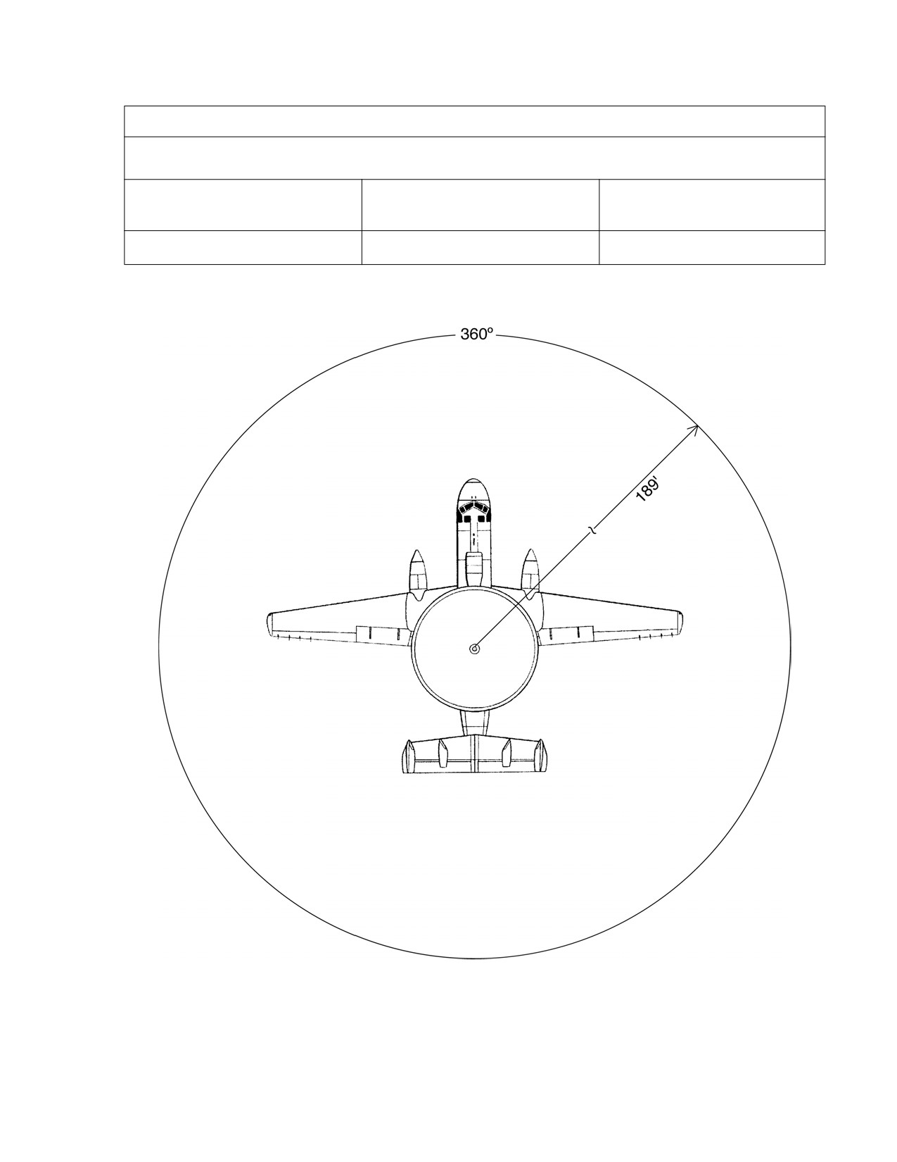
NAVSEA OP 3565/NAVAIR 16-1-529
VOLUME 1 SIXTH REVISION
Aircraft
E-2C HAWKEYE
HERP SAFE
Radars
ANTENNA SCAN ANGLE
Separation Distance
AN/APS-145
57.6 METERS/189.0 FEET
360º
FIGURE 2-2. Aircraft Radiation Patterns (Continued)
2-33

NAVSEA OP 3565/NAVAIR 16-1-529
VOLUME 1 SIXTH REVISION
Aircraft
E-6A MERCURY (TACAMO)
HERP SAFE
Radars
ANTENNA SCAN ANGLE
Separation Distance
AN/APS-133(V)
10.2 METERS/34.0 FEET
±90º
FIGURE 2-2. Aircraft Radiation Patterns (Continued)
2-34

NAVSEA OP 3565/NAVAIR 16-1-529
VOLUME 1 SIXTH REVISION
Aircraft
EA-6B PROWLER
HERP SAFE
Radars
ANTENNA SCAN ANGLE
Separation Distance
AN/APS-130B(V)1
7.0 METERS/23.0 FEET
±57º
FIGURE 2-2. Aircraft Radiation Patterns (Continued)
2-35

NAVSEA OP 3565/NAVAIR 16-1-529
VOLUME 1 SIXTH REVISION
Aircraft
F-14 (ALL MODELS)
HERP SAFE
Radars
ANTENNA SCAN ANGLE
Separation Distance
AN/AWG-9 OR AN/APG-71
187.8 METERS/616.0 FEET
AS SHOWN
FIGURE 2-2. Aircraft Radiation Patterns (Continued)
2-36

NAVSEA OP 3565/NAVAIR 16-1-529
VOLUME 1 SIXTH REVISION
Aircraft
F/A-18 (ALL MODELS)
HERP SAFE
Radars
ANTENNA SCAN ANGLE
Separation Distance
AN/APG-65 OR AN/APG-73
40.8 METERS/134.0 FEET
±70º
FIGURE 2-2. Aircraft Radiation Patterns (Continued)
2-37
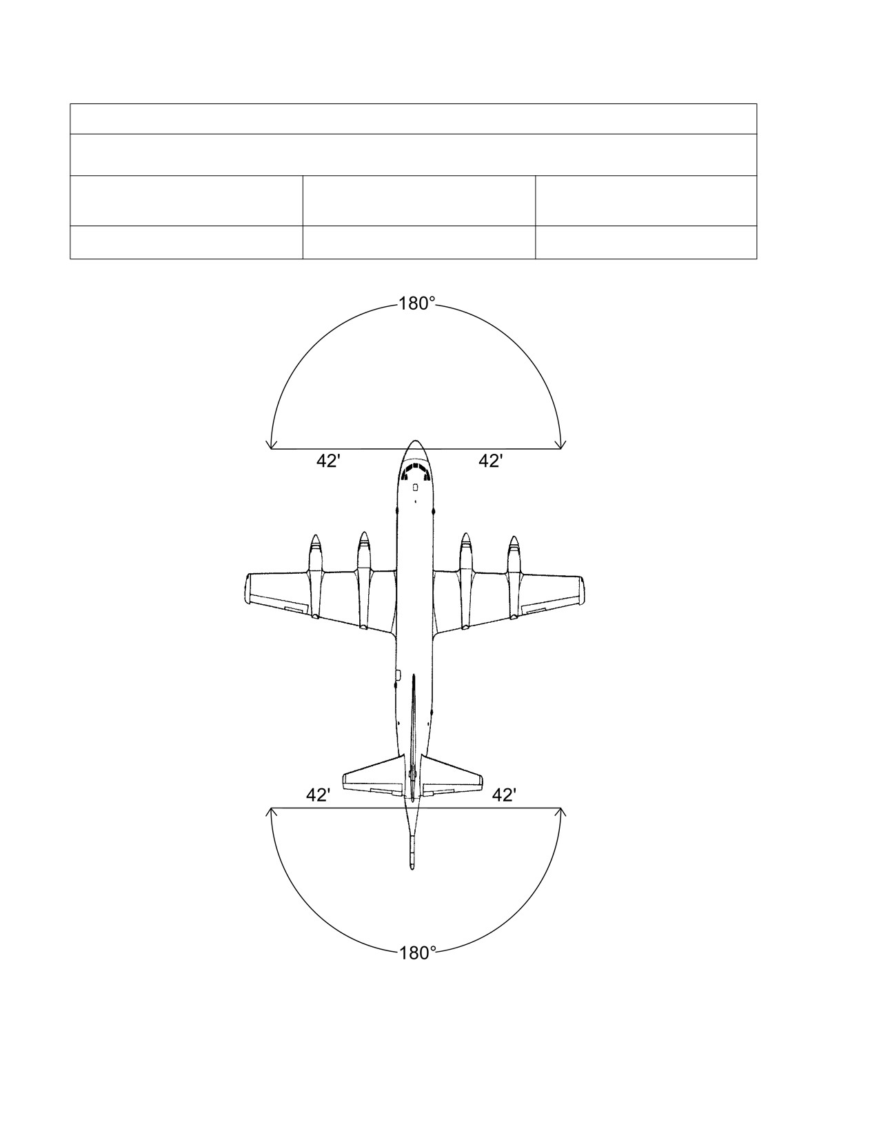
NAVSEA OP 3565/NAVAIR 16-1-529
VOLUME 1 SIXTH REVISION
Aircraft
P-3C ORION
HERP SAFE
Radars
ANTENNA SCAN ANGLE
Separation Distance
AN/APG-66
12.7 METERS/42.0 FEET
±90º (NOSE AND TAIL)
FIGURE 2-2. Aircraft Radiation Patterns (Continued)
2-38

NAVSEA OP 3565/NAVAIR 16-1-529
VOLUME 1 SIXTH REVISION
Aircraft
P-3C ORION
HERP SAFE
Radars
ANTENNA SCAN ANGLE
Separation Distance
AN/APS-115B
18.8 METERS/62.0 FEET
±90º (NOSE AND TAIL)
FIGURE 2-2. Aircraft Radiation Patterns (Continued)
2-39

NAVSEA OP 3565/NAVAIR 16-1-529
VOLUME 1 SIXTH REVISION
Aircraft
P-3C ORION
HERP SAFE
Radars
ANTENNA SCAN ANGLE
Separation Distance
AN/APS-137B(V)5
33.7 METERS/111.0 FEET
±90º (NOSE AND TAIL)
FIGURE 2-2. Aircraft Radiation Patterns (Continued)
2-40

NAVSEA OP 3565/NAVAIR 16-1-529
VOLUME 1 SIXTH REVISION
Aircraft
S-3B VIKING
HERP SAFE
Radars
ANTENNA SCAN ANGLE
Separation Distance
AN/APS-137A(V)1
33.5 METERS/110.0 FEET
360º
FIGURE 2-2. Aircraft Radiation Patterns (Continued)
2-41

NAVSEA OP 3565/NAVAIR 16-1-529
VOLUME 1 SIXTH REVISION
Aircraft
SH-60B SEAHAWK
HERP SAFE
Radars
ANTENNA SCAN ANGLE
Separation Distance
AN/APS-124
17.4 METERS/57.0 FEET
360º
FIGURE 2-2. Aircraft Radiation Patterns (Continued)
2-42

NAVSEA OP 3565/NAVAIR 16-1-529
VOLUME 1 SIXTH REVISION
Aircraft
T-39N SABERLINER
HERP SAFE
Radars
ANTENNA SCAN ANGLE
Separation Distance
AN/APG-66N
12.7 METERS/42.0 FEET
±60º
FIGURE 2-2. Aircraft Radiation Patterns (Continued)
2-43
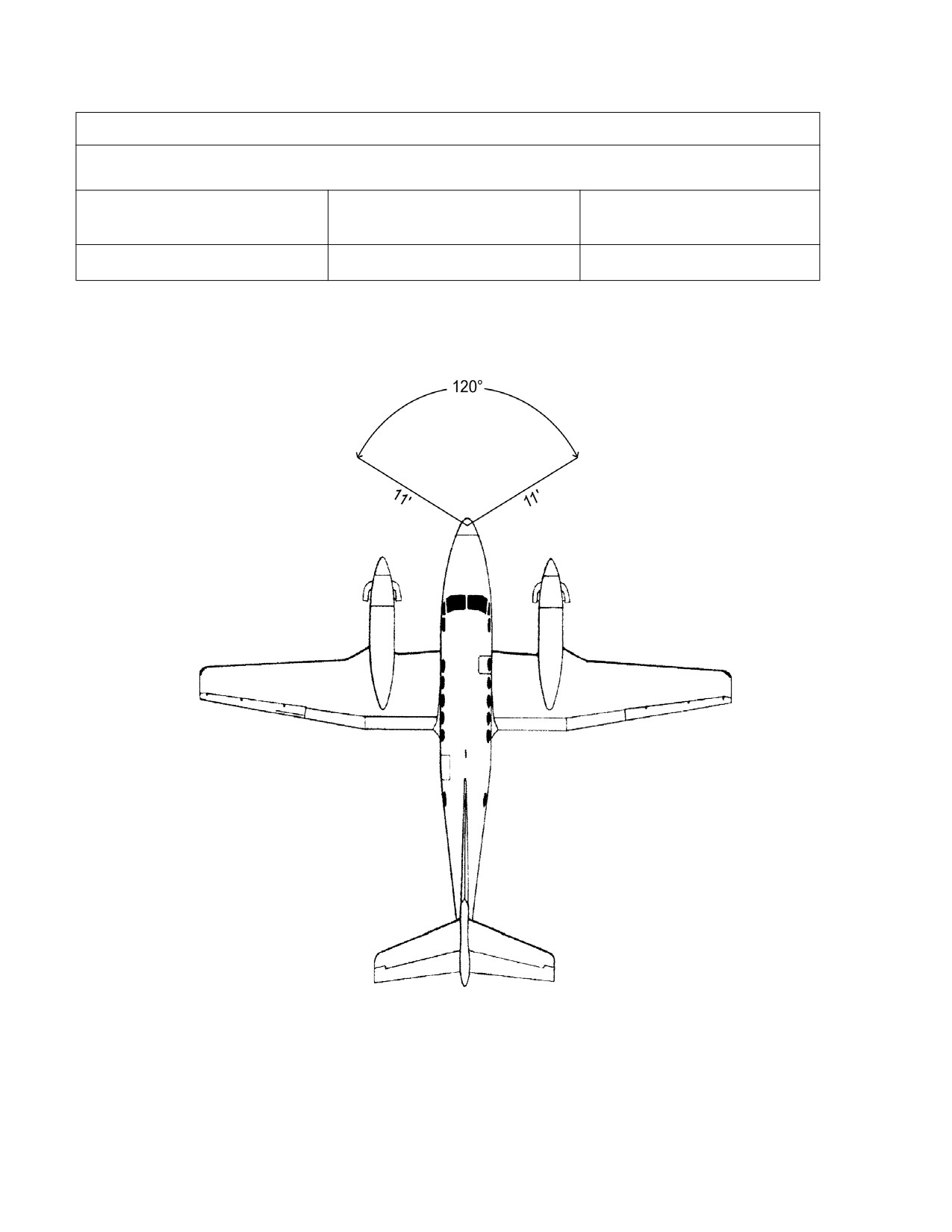
NAVSEA OP 3565/NAVAIR 16-1-529
VOLUME 1 SIXTH REVISION
Aircraft
UC-12B HURON
HERP SAFE
Radars
ANTENNA SCAN ANGLE
Separation Distance
COLLINS WXR-270
3.3 METERS/11.0 FEET
±60º
FIGURE 2-2. Aircraft Radiation Patterns (Continued)
2-44
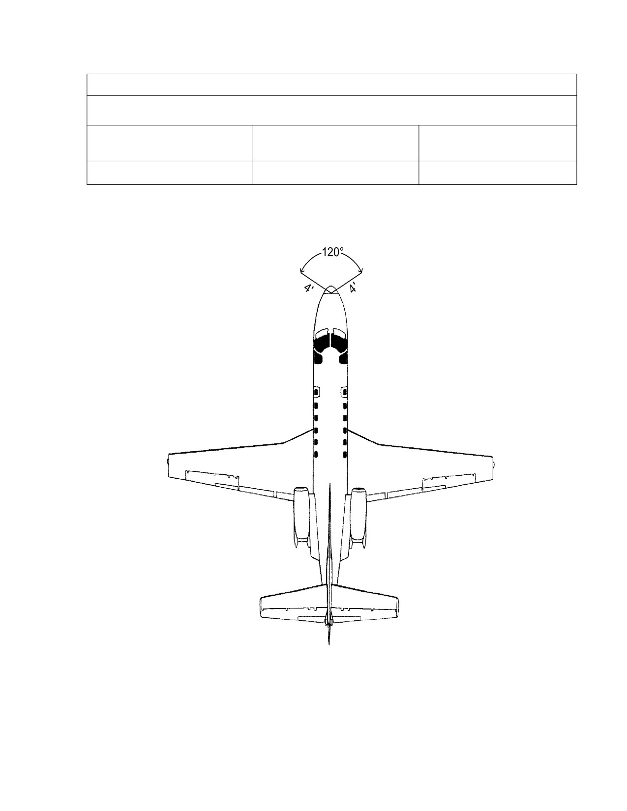
NAVSEA OP 3565/NAVAIR 16-1-529
VOLUME 1 SIXTH REVISION
Aircraft
UC-35 CITATION
HERP SAFE
Radars
ANTENNA SCAN ANGLE
Separation Distance
HONEYWELL PRIMUS 650
1.2 METERS/4.0 FEET
±60º
FIGURE 2-2. Aircraft Radiation Patterns (Continued)
2-45

NAVSEA OP 3565/NAVAIR 16-1-529
VOLUME 1 SIXTH REVISION
Aircraft
V-22 OSPREY
HERP SAFE
Radars
ANTENNA SCAN ANGLE
Separation Distance
AN/APQ-174B
7.1 METERS/23.0 FEET
±70º
FIGURE 2-2. Aircraft Radiation Patterns (Continued)
2-46
NAVSEA OP 3565/NAVAIR 16-1-529
VOLUME 1 SIXTH REVISION
CHAPTER 3
RF BURNS
3-1. SCOPE
This chapter discusses radio-frequency (RF) burns, why they can occur, and the
procedures for minimizing RF burn hazards. An RF burn hazard will exist if there is a
sufficiently high induced RF voltage on a metallic object to cause pain, visible skin damage, or
involuntary reaction to a person who comes in contact with the object. The RF burn
phenomenon is distinct from hazards of electromagnetic radiation to personnel and electrical
shock.
3-2. RF BURNS FROM CARGO-HANDLING EQUIPMENT
3-2.1
GENERAL. The use of high-frequency (HF) transmitters (1 kW and up), and the
complicated structure and rigging aboard ship, especially cargo ships, has increased the
probability of voltages being induced on various objects. The handling of metallic cargo lines
while shipboard HF transmitters are radiating can be hazardous to ship’s personnel. On
numerous occasions, RF voltages have been encountered on items such as crane hooks,
running rigging, booms, missile launchers, and parked aircraft. These voltages, which may be
sufficient to cause injury, are induced on the metallic items by radiation from nearby transmitting
antennas.
3-2.2
RF BURN EFFECTS. An RF burn is the result of RF current flow through that portion of
the body in direct contact with a conductive object (in which an RF voltage has been induced) or
at the site of a spark discharge (no direct contact with a conductive object). Any burn injury that
occurs is entirely the result of heat produced by current flow through the resistance of the skin.
Current flow through a resistance produces heat regardless of the nature of the circuit. The
effect of the heat on a person ranges from warmth to painful burns. The specific level at which
contact with RF voltage should be classified as an RF burn hazard is not distinct. Hazardous,
for the purpose of this section, is defined as the RF voltage that will cause a person pain or
visible skin damage, or will cause an involuntary reaction. The term "hazard" does not include
the lower voltages that cause annoyance, a stinging sensation, or moderate heating of the skin.
Naval Sea Systems Command (NAVSEA), Code 53H, has established that an open-circuit RF
voltage exceeding 140 volts on an item in an RF radiation field is to be considered hazardous.
However, field tests have shown that, because of the many variables involved, it is not
uncommon to encounter significantly higher voltages that do not result in a burn problem.
3-2.3
ELECTRICAL CHARACTERISTICS OF METALLIC OBJECTS.
3-2.3.1 All metallic items, regardless of intended use, have electrical properties of resistance,
inductance, and capacitance. These properties depend upon the material, the size and shape
of the objects, and the proximity of the objects to each other. The effect of the inductance and
capacitance is frequency dependent. A configuration of metallic objects can be represented by
3-1

NAVSEA OP 3565/NAVAIR 16-1-529
VOLUME 1 SIXTH REVISION
an approximately equivalent electrical circuit such as that illustrated by figure 3-1, a typical
example of cargo-handling equipment. Potentially harmful voltages (current) may be generated
when radiated electromagnetic energy couples to such equipment. At radio frequencies, the
reactive components are the significant ones, and maximum voltage will be developed at a
frequency and location where the inductive (L) and capacitance (C) reactances are equal; i.e.,
where there is a resonant circuit. This behavior is characteristic of an antenna.
3-2.3.2 Metallic objects having the physical and electrical characteristics of an antenna are
commonplace aboard ships. Long lengths of metallic lines are particularly efficient interceptors
of RF energy. The amplitude of the induced RF voltage depends on:
a. The length of the line with respect to the wavelength of the exciting RF field.
b. The nearness of the line to a radiating antenna.
c. The power being radiated by the transmitting antenna.
d. The orientation of the line with respect to the transmitting antenna.
Since most shipboard antennas transmit vertically polarized fields, voltages are more likely to
be induced in vertical lines than in lines oriented in other directions.
3-2.3.3 As a practical matter, whether an induced voltage creates an RF burn hazard also
depends upon whether personnel will come into contact with the object. Generally, only the
voltage between an object and the deck is important.
3-2.3.4 Cargo ships, with their long lengths of metallic cables, are more likely to encounter the
RF burn problem than other types of ships, although the problem is not limited to that type.
Figure 3-1.
Electrical Equivalent of Cargo-Handling Equipment
3-2
NAVSEA OP 3565/NAVAIR 16-1-529
VOLUME 1 SIXTH REVISION
3-2.3.5 When conditions conducive to RF burn hazards exist aboard ship, proper
measurements are necessary to determine the extent of the hazard. Valid data from
comprehensive tests will lead to recommendations to ensure maximum personnel safety with a
minimum of operational limitations.
3-3. RF BURN HAZARD REDUCTION TECHNIQUES
3-3.1
INTRODUCTION. While there is no universally applicable method to completely
eliminate RF burn hazards, there are several approaches to eliminating the problem in some
cases or, in other cases, reducing it to manageable proportions. NAVSEA is continuing to
search for methods to eliminate the hazard.
3-3.2
LIMITING BODY CONTACT CURRENT. As discussed in Department of Defense
Instruction (DODINST) 6055.11, for frequencies between 100 kHz and 100 MHz, limiting body
contact current to a maximum of 100 mA will significantly reduce the likelihood of RF burns. For
frequencies between 3 kHz and 100 kHz, the contact current limit is frequency dependent.
3-3.3
HOOK INSULATORS. One method of eliminating the RF burn hazard on boom whip
and downhaul hooks is to install an insulator link between the rigging and the hook. Tests have
shown that these insulators are effective in the prevention of RF burns to the extent that contact
with the hook itself will not injure anyone, but the RF voltage and potential burn hazard above
the insulator remains unaffected. Unfortunately, numerous equipments involved in the RF burn
problem are not amenable to the use of an insulating link.
3-3.4
NONMETALLIC MATERIALS. Another approach being pursued is the use of
nonmetallic materials for applications where the RF burn hazard is a problem. Objects that can
be made of nonconducting material will not be susceptible to induced voltages. At the present,
though, there is no suitable nonmetallic substitute for the wire rope used on cargo equipment.
3-3.5
ANTENNA RELOCATION. Eliminating RF burn hazards by relocating antennas is often
tempting but seldom practical. Because so many factors are involved in designing a shipboard
antenna system, antenna relocation is not a feasible general solution to the RF burn hazard
problem. Nevertheless, antenna relocation should not be abandoned as an impossibility.
3-3.6
OPERATIONAL PROCEDURES. In some cases, the RF burn hazard can be eliminated
only through the use of restrictive operating procedures that govern the simultaneous use of
transmitters and cargo equipments. These procedures incorporate the use of techniques such
as operation of transmitters at reduced power and the prohibition of simultaneous use of certain
combinations of antennas, frequencies, and cargo-handling equipments. The use of
operational limitations will reduce the effectiveness of all equipments involved; therefore, these
limitations must not be excessively restrictive. Effective operational procedures can be
developed only after a shipboard RF burn survey has been conducted. Following this survey,
specific operational procedures must be developed by persons who have a thorough
knowledge of the operational requirements of the ship and have the authority to designate
which operations and equipments have priority over others.
3-3
NAVSEA OP 3565/NAVAIR 16-1-529
VOLUME 1 SIXTH REVISION
3-3.7
RF RADIATION HAZARD WARNING SIGNS. In cases where RF burn hazards cannot
be eliminated, the probability of personnel coming in contact with hazardous voltages can be
reduced through the use of RF radiation hazard warning signs, as discussed in paragraph 2-
2.2. The locations for posting the signs should be chosen with care to ensure that they will
pinpoint, as nearly as possible, the exact location of potential hazards. Indiscriminate and
excessive use of the signs will reduce their effectiveness.
3-4
NAVSEA OP 3565/NAVAIR 16-1-529
VOLUME 1 SIXTH REVISION
CHAPTER 4
BIOLOGICAL RADIATION HAZARD FROM LASER DEVICES
4-1. INTRODUCTION
4-1.1 The acronym "Laser" is derived from the initial letters of the words "Light Amplification by
Stimulated Emission of Radiation." The term "optical maser" was used earlier because the
original work was done with microwaves. Figure 4-1 illustrates the laser wavelength spectrum.
The biological effects of laser radiation are similar to light generated by high-intensity,
conventional ultraviolet (UV), infrared, and visible light sources such as the sun, nuclear
explosions, or arc lamps. However, the chance of eye or skin damage is greater from laser
radiation because the laser output is highly coherent (in phase), and the high intensity is
localized into a very directional beam. When laser radiation is absorbed by the body or eyes, it
is converted into heat which, in turn, causes redness, blistering, and, if intense enough, even
charring of the skin or visual impairment, which may be permanent.
4-1.2 Developments in laser technology have resulted in an increase in the use of these
devices for military applications, both for research and operational use. The widespread use of
these systems increases the probability of personnel exposure to injurious intensities of laser
radiation. Adequate safeguards are needed, since injury may occur at considerable distance.
All equipment containing lasers, and all lasers produced after 2 August 1976, must comply with
the Radiation Control for Health and Safety Act, Code of Federal Regulations (CFR) Title 21,
Subchapter J, Part 1040, unless it has an exemption from the National Center for Devices and
Radiological Health, Rockville, Maryland. The procedures for using lasers safely are contained
in American National Standards Institute (ANSI) Z136.1. The following provides some of the
essential safety requirements for use at Navy shore installations and aboard ships.
4-2. GENERAL PRECAUTIONS APPLICABLE TO ALL LASER INSTALLATIONS
4-2.1 For a summary of hazards and sample laser safety emission control (EMCON) bills, refer
to Chief of Naval Operations Instruction (OPNAVINST) 5100.27/Marine Corps Order (MCO)
5104.1 (series), Navy Laser Hazards Control Program.
4-2.2 Unprotected personnel shall never be exposed to laser radiation in excess of the
maximum permissible exposure (MPE) levels specified in ANSI Z136.1.
4-2.3 Direct viewing of laser beams, even during optical alignment, is prohibited when levels
are greater than the MPE.
4-2.4 Optical viewing systems such as lenses, telescopes, etc., may increase the hazard to the
eye.
4-1

NAVSEA OP 3565/NAVAIR 16-1-529
VOLUME 1 SIXTH REVISION
4-2
NAVSEA OP 3565/NAVAIR 16-1-529
VOLUME 1 SIXTH REVISION
4-2.5 All involved personnel shall be trained to avoid looking directly at an operating laser or its
reflection. Personnel protective equipment (laser eye protection), specifically designed and
marked (with optical density and wavelength) for protection against radiation from the laser
system in use, shall be used when engineering or procedural controls are inadequate to
eliminate radiation levels in excess of the MPE.
4-2.6 Laser protective eyewear shall be marked with optical density values and wavelength for
which protection is afforded, and shall be issued to involved personnel. The eyewear shall
provide a snug fit. Periodic inspections of the goggles shall include:
a. Inspection of the attenuator material for pitting, crazing, cracking, etc.
b. Inspection of the goggle frame for mechanical integrity and leaks.
4-2.7 Only authorized personnel shall operate laser systems.
4-2.8 Spectators shall not be allowed access to the laser control area unless appropriate
supervisory approval has been obtained and protective measures taken.
4-2.9 At least two people should be present at all times when lasers are in operation so that
first aid may be rendered in the event of an injury and to prevent access by unauthorized
personnel. Where the operation allows, a countdown procedure should be followed to minimize
unnecessary exposure by donning laser eye protection and/or moving out of the path of the
laser beam.
4-2.10 Reflecting surfaces such as mirrors, bottles, windows, and metal, or other surfaces
which have a high coefficient for specular reflection, shall be eliminated from the beam path or
shall be faced and/or surrounded with diffuse substances to absorb the energy.
4-2.11 Lasers and laser beams should be contained within a suitably controlled equipment or
space so that noninvolved personnel in such an area cannot be accidentally injured. Laser
beams emitted by an unenclosed system must be terminated at the end of the beam path if the
exposure level is greater than the maximum allowable level. The backstop shall be of material
that will absorb the particular wavelength. Special care in absorbing and containing the laser
radiation must be taken, especially when the laser is emitting energy in the UV or infrared
portions of the spectrum, because an observer might receive damage to the eyes without being
aware of the reflection. Laser controls must be located to prevent operator exposure to unsafe
levels of radiation.
4-2.12 Hazardous byproducts may result from the reaction of the laser radiation (especially UV
laser radiation) with air and other substances (toxic/explosive gases, skin irritants, radio-
frequency/UV/x-ray emissions, plasma).
4-2.13 The following are examples (sources) of hazards typically associated with laser
operations:
a. High-voltage electrical hazards.
b. Use of cryogenics.
4-3
NAVSEA OP 3565/NAVAIR 16-1-529
VOLUME 1 SIXTH REVISION
c.
Compressed gases.
d. Carcinogenic material.
e. Noise.
f.
Arc lamps, filament lamps, capacitors (explosion hazards).
g. Targets (which may shatter/explode).
h. Ionizing radiation.
i.
Incoherent optical and UV radiation from laser discharge tubes or flash lamps.
Proper personnel protection and procedures shall be provided in the use of cryogenics.
Compressed gas bottles shall be secured. All laser discharge tubes or flash lamps, the laser
target, capacitors, and all elements of the optical train which may shatter shall be adequately
contained. All voltages in excess of 30 volts shall be guarded. All incidental radiation shall be
adequately shielded. The laser spaces shall be adequately ventilated to remove toxic gases.
All toxic materials shall be so marked and adequately controlled. Smoking, eating, or drinking
in laser beam areas should be prohibited.
4-3. LASER CLASSIFICATION AND LABELING
4-3.1 All lasers, other than military exempt lasers, must be classified and labeled by the
manufacturers per CFR Title 21, Part 1040.10. Military exempt lasers are classified per ANSI
Z136.1. This classification system is based on laser output parameters. There are four laser
hazard classifications that determine the required extent of radiation safety controls. These
range from class I lasers that are safe for direct beam viewing under most conditions, to class
IV lasers that require the strictest controls. Laser product classification pertains to intended use
only. When a laser product is disassembled for maintenance and protective features are
removed, the laser classification may change to a more hazardous class. Details concerning
laser classification are in CFR Title 21, Part 1040.10, and ANSI Z136.1. Controls for each class
are addressed in OPNAVINST 5100.27/MCO 5104.1 (series) and its referenced instructions.
4-3.2
MILITARY EXEMPT LASERS. As per OPNAVINST 5100.27/MCO 5104.1 (series), the
Navy Laser Safety Review Board (LSRB) must approve most class III and class IV lasers, and
all military exempt lasers, prior to their use within the Department of the Navy. All lasers used
for combat, combat training, or classified in the interest of national security are eligible for this
exemption and, if so designated by the LSRB, are exempt from federal requirements applicable
to commercial products. Military exempt lasers must be labeled as shown in figure 4-2 (or as
specified by the LSRB) and, upon request, an inventory of a command’s class III, class IV, and
military exempt lasers shall be sent to the Bureau of Medicine and Surgery (MED 212) per
OPNAVINST 5100.27/MCO 5104.1 (series).
4-4

NAVSEA OP 3565/NAVAIR 16-1-529
VOLUME 1 SIXTH REVISION
CAUTION FOR MILITARY EXEMPT LASERS
This electronic product has been exempted from FDA radiation safety performance
standards prescribed in the Code of Federal Regulations, Title 21, Chapter I, Sub-
chapter J, pursuant to Exemption No. 76EL-01DOD issued on July 26, 1976. This
product should not be used without adequate protective devices or procedures.
FIGURE 4-2. Military Laser Exemption Label
4-3.3
LASER RANGE AND BUILDING WARNING SIGNS. Warning signs, as specified in
section 4.7 of ANSI Z136.1, shall be posted at the entrances to laser ranges and buildings in
accordance with sections 4.3.9, 4.3.10, 4.3.11, and 4.3.12 of ANSI Z136.1.
4-3.4 For all invisible radiation (less than 400 nanometers or greater than 700 nanometers) the
word "invisible" shall precede the word "radiation" on all warning signs and labels. Each class
II, III, and IV laser product which is not military exempt must state the maximum power output of
laser radiation, the pulse duration when appropriate, and the laser medium or emitted
wavelength on the warning label attached to the device.
4-3.5 Laser safety warning signs for posting at laser facilities and at laser ranges are stocked at
the Naval Inventory Control Point, Naval Publication and Forms Branch, 700 Robbins Avenue,
Philadelphia, PA 19111-5098. For information concerning these forms, contact (215) 697-2626
or DSN 442-2626.
4-4. TRAINING
All personnel in areas using lasers shall be informed about the potential hazard
associated with accidental exposure to this form of radiation. In particular, the extraordinary
danger of eye damage due to the optical amplification and efficient absorption by this organ
shall be emphasized. Class III and IV lasers may also cause skin damage or damage to
material by fire or explosion due to rapid heating from a focused beam. At a minimum, laser
safety training shall include the requirements of OPNAVINST 5100.27/MCO 5104.1 (series).
4-5. MEDICAL SURVEILLANCE
Bureau of Medicine and Surgery Instruction (BUMEDINST) 6470.23 (series) gives
medical surveillance requirements and casualty management procedures for personnel
exposed to laser radiation.
4-6. COMMAND LASER SAFETY PROGRAM
4-6.1 When required [based upon type of laser(s) employed], each command should establish
a laser safety program and appoint a laser safety officer as per OPNAVINST 5100.27/MCO
5104.1 (series) and ANSI Z136.1.
4-5
NAVSEA OP 3565/NAVAIR 16-1-529
VOLUME 1 SIXTH REVISION
4-6.2 When required, a laser safety officer shall be appointed to coordinate the safety aspects
of lasers and their use. This appointment shall be contingent on the successful completion of
laser safety officer training as described in OPNAVINST 5100.27/MCO 5104.1 (series).
4-7. CALCULATION OF LASER SAFE DISTANCES AND PERMISSIBLE LASER
EXPOSURE LEVELS
Methods to calculate laser safe distances and permissible laser exposure levels are
specified in appendix B of ANSI Z136.1. As per OPNAVINST 5100.27/MCO 5104.1 (series),
only certified Laser Safety Specialists may make such calculations. The Navy’s primary point of
contact for making these calculations is Naval Surface Warfare Center, Dahlgren Division
(G71). See paragraph 4-8.1 for laser technical assistance information.
4-8. LASER TECHNICAL ASSISTANCE
4-8.1 Interested parties may obtain technical assistance and advice regarding laser safety by
accessing the official Navy Web site (www.navylasersafety.com) or by contacting:
a. For medical and industrial laser operations: Navy Environmental Health Center,
620 John Paul Jones Circle, Suite 1100, Portsmouth, VA 23708-2103, (757) 953-0700,
(757) 621-1967, DSN 377-0700, or DSN 377-1967.
b. For laser systems and certification surveys of laser firing ranges (funding for
services shall be provided by the requesting command):
1. Laser Hazard Evaluations and Range Surveys: Commander, Naval Surface
Warfare Center, Dahlgren Division (G71), 17320 Dahlgren Road, Dahlgren, VA 22448-5100,
(540) 653-1060/1149, DSN 249-1060/1149, fax (540) 653-8453, www.navylasersafety.com.
2. Laser Range Surveys: Commander, Naval Surface Warfare Center, Corona
Division (SE41), P.O. Box 5000, Corona, CA 92878-5000, (909) 273-4142 or DSN 933-4142.
c.
For laser bioeffects and medical research issues, or assistance in evaluating laser-
induced injuries, contact the Naval Health Research Center-Detachment Brooks AFB, 8301
Navy Road, Brooks AFB, TX 78235-5365, (210) 536-4699/6552, DSN 240-4699/6552, or fax
(210) 536-6439/6528.
d. For guidance on laser exposure limits and health issues, contact the Non-Ionizing
Radiation Health Branch, Bureau of Medicine and Surgery (MED 212), 2300 E Street NW,
Washington, DC 20372-5300, (202) 762-3444, DSN 762-3444, or fax (202) 762-0931.
4-8.2 Naval Sea Systems Command (SEA-00T) is the technical lead agent for all Navy/Marine
Corps laser safety. Naval Surface Warfare Center, Dahlgren Division (G71), is the lead Navy
technical laboratory for all technical issues pertaining to lasers used in, by, and for the Navy and
Marine Corps.
4-6
NAVSEA OP 3565/NAVAIR 16-1-529
VOLUME 1 SIXTH REVISION
CHAPTER 5
IONIZING RADIATION
5-1. INTRODUCTION
Ionizing radiation is the electromagnetic or particulate emanations produced by radiation
sources. These emanations can cause ionization; that is, the ejection of electrons from atoms.
Ionization within the cells or tissues of the body can occur as the result of exposure to alpha
particles, beta particles (electrons), neutrons, protons, or other atomic or subatomic particles, or
of exposure to gamma rays, x-rays, or other electromagnetic waves capable of ejecting
electrons from atoms.
5-2. UNITS OF MEASUREMENT
a. Electron Volt (eV) - A unit of energy equal to the energy gained by an electron in
passing from a point of low potential to a point one volt higher in potential. One eV equals
1.602x10⁻¹² ergs (1.602x10⁻¹⁹ joules) of energy.
b. Rem - An equilibration of the dose of ionizing radiation to the body in terms of its
estimated biological effect, relative to an absorbed dose of 1 roentgen of high-voltage x-rays.
The rem shall be the unit of dose for record purposes.
c. Roentgen (R) - That amount of x- or gamma radiation which will produce 2.083x10⁹
ion pairs in 1 cc of air under standard conditions. For the purpose of these regulations, 1
roentgen of x- or gamma radiation is considered to deliver 1 rad.
d. Rad - A unit of absorbed ionizing radiation equal to 100 ergs of energy per gram.
5-3. METHODS OF DETECTING IONIZING RADIATION
Ionizing radiation cannot be detected by the senses. It can be detected only by devices
which respond to the ionizing properties of radiation. These detecting devices include Geiger
counters, scintillation counters, ionization chambers (including pocket dosimeters), phosphors,
transformation reaction counters (including photographic emulsions), and free radical counters.
5-4. RADIAC EQUIPMENT
The purpose of radiac equipment is to detect and indicate the amount of radioactivity
present in a given area. The type of radioactivity detected (alpha and beta particles, x-ray,
gamma radiation, fast and slow neutrons) is determined by the type of radiac equipment used.
Radiac equipments vary from small, portable, battery-operated sets to large, integrated
monitoring systems requiring associated electronic equipment. Basically, radiac equipments
contain one or a combination of the following:
5-1
NAVSEA OP 3565/NAVAIR 16-1-529
VOLUME 1 SIXTH REVISION
a. Radiac Detector - A device that is sensitive to radioactivity of free nuclear particles
and reacts in a manner that can be interpreted or measured by various means.
b. Radiacmeter - A device that detects the presence of radioactivity and indicates the
dose rate or total dose.
c. Computer-Indicator - A device that computes and indicates radiac data received from
the radiac detector or detectors.
5-5. HAZARD LEVEL
All personnel working in high-intensity levels of radioactivity must exercise caution to
prevent bodily damage. While the radiation from radioactive substances cannot be seen or felt,
prolonged or extensive exposure may result in serious damage. One-tenth of a roentgen per
week (0.1 R/week or 100 mR/week) is considered to be the maximum permissible exposure.
5-6. PRECAUTIONS
5-6.1. Safety precautions and instructions on handling radioactive material are contained in
Naval Medical Command (NAVMED) Publication P-5055, Radiation Health Protection Manual,
and various National Institute of Standards and Technology handbooks.
5-6.2. Precautions should be taken not to attempt any measurement of ionic radiation while
located in a radio-frequency (RF) electromagnetic field. Radiac detectors are susceptible to
electromagnetic fields and will produce an erroneous reading which could be mistaken for ionic
radiation. The reverse is also true. Do not attempt to measure RF radiation while in the
environment of ionic radiation.
5-6.3. The accumulated dose of radiation to the whole body, head and trunk, active blood-
forming organs, genitals, or lens of the eye shall not exceed 3 rem in any calendar quarter nor 5
(N-18) rem total lifetime dose, where N equals the present age in years.
5-2
NAVSEA OP 3565/NAVAIR 16-1-529
VOLUME 1 SIXTH REVISION
CHAPTER 6
HAZARDS OF ELECTROMAGNETIC RADIATION TO FUEL
6-1. INTRODUCTION AND BACKGROUND
6-1.1. A fuel-handling operation is defined as the act of transferring fuel from one container to
another. This includes, but is not limited to, fueling aircraft, vehicles, or equipment from a pump
or a portable container; transferring fuel from a storage container to a fuel truck; and transferring
fuel from a pump to a portable container. While fixed shore-station antennas are usually located
a sufficient distance from fuel pumps and fuel storage areas in order to prevent a hazard, care
should be taken to ensure that fueling operations involving transfer of fuel from a portable
container to a vehicle or equipment (such as lawnmowers, generators, construction equipment,
etc.) do not occur within the prescribed safe separation distances for shore-station transmitters
if main-beam illumination of the area is possible. In addition, mobile and handheld transmitters
should not be operated within the minimum safe separation distance from any fuel-handling
operation.
6-1.2. The possibility of accidentally igniting fuel vapors by radio frequency (RF)-induced arcs
during fuel-handling operations in proximity to high-powered communication and radar
transmitting antennas has been the subject of extensive study and research. Tests aboard
ships and in laboratories have shown that, while it is possible to ignite volatile fuel-vapor
mixtures by induced RF energy, the probability of ignition during normal fueling procedures is
remote, given the number of conditions that must exist simultaneously in order to support
combustion.
6-1.3. The probability of accidental ignition has been reduced in recent years by the following:
a. Location of transmitting antennas away from fueling stations and vents.
b. Introduction of pressurized fueling systems on aircraft.
c. The move to almost exclusive use of JP-5 aircraft fuels aboard ship.
Even though the potential fuel hazard from electromagnetic radiation may not be as great as
formerly believed and has been reduced by the foregoing measures, it is still present when
handling the more volatile JP-4 fuel, motor vehicle gasoline (MOGAS), or aviation gasoline
(AVGAS). Personnel handling fuels afloat and ashore should be aware of this potential hazard,
which is more fully described herein.
6-2. PHYSICAL NATURE OF COMBUSTION
6-2.1. The probability of ignition of fuel vapors by RF-induced arcs is small, since the following
conditions must occur simultaneously for ignition to take place:
6-1

NAVSEA OP 3565/NAVAIR 16-1-529
VOLUME 1 SIXTH REVISION
a. A flammable fuel-air mixture must be present within range of the induced arcing.
b. The arc must contain a sufficient amount of energy to cause ignition.
c. The gap across which the arc occurs must be a certain minimum distance.
6-2.2. The limits of flammability of MOGAS are between 1.25 percent and 7.6 percent by
volume of gasoline vapor in the air. Handling of gasoline under normal operating conditions
does not produce a flammable atmosphere except close to fuel vents, open fuel inlets, or spilled
gasoline. With no ventilation, flammable gasoline vapors, being heavier than air, may travel or
spill down an inclined surface, such as that provided by a wing or fuselage of an aircraft, before
becoming diluted. However, if air movement (wind) is present, the gasoline vapor is diluted and
dispersed rapidly, reducing the zone of possible ignition. The flammability of hydrocarbon fuels
is also influenced by temperature. Figure 6-1 shows the effect on flammable ranges due to
increasing fuel temperatures. Figure 6-2 shows the temperature-flammability regions for
different types of commonly used fuels.
FIGURE 6-1. Effect of Temperature in Generating Hydrocarbon Fuel Flammable Vapors
6-2

NAVSEA OP 3565/NAVAIR 16-1-529
VOLUME 1 SIXTH REVISION
FIGURE 6-2. Temperature-Flammability Ranges for Fuels
6-2.3. The presence of an odor of gasoline is not a reliable indicator of flammability since the
effect of odorous substances varies among observers. However, in comparative tests of
6-3
NAVSEA OP 3565/NAVAIR 16-1-529
VOLUME 1 SIXTH REVISION
individual response, it was found that the odor of gasoline was quite perceptible at
concentrations of less than 1 percent of the lower flammability limit. At 100 percent, a very
strong odor existed; at 125 percent, the gas-air mixture was noticeably irritating to the eyes and
nasal passages.
6-2.4. Although tests conducted under laboratory conditions to determine the minimum arc
energy necessary to cause ignition have been inconclusive, it is known that the arc energy is a
determining factor for ignition of fuel-air mixtures. From actual measurements of voltages and
currents on aircraft located on a carrier deck near an energized transmitting antenna, it was
found that a volt-ampere product of 50 or more was required to ignite gasoline in an explosive
vapor test device. Measurements also have been made on various fueling configurations to
relate the required 50 volt-ampere ignition energy to the surrounding electric field intensity.
Field intensity can, in turn, be related to the radiated power and distance from an antenna.
6-2.5. A minimum spark gap of about 0.5 millimeter (0.02 inch) is required for ignition of a fuel-
air mixture. In terms of fueling operations, this generally requires a metal-to-metal contact and
subsequent withdrawal to produce a drawn arc of sufficient length to ignite a fuel-air mixture.
Ensuring that the static ground wires, tie-down cables, and other metallic connections to the
aircraft or motor vehicle are properly made before fueling or defueling operations commence,
and are not disturbed until after the operation is finished, will greatly reduce the possibility of
accidental ignition.
6-3. HANDLING PRECAUTIONS FOR FUELS IN AN RF ENVIRONMENT
6-3.1
INTRODUCTION. It is assumed that personnel engaged in fueling operations will be
familiar with and observe the safety precautions contained in applicable Naval Sea Systems
Command/Naval Air Systems Command instructions and directives.
Three hydrocarbon-based fuels are currently used throughout the Navy: marine diesel,
aviation jet fuel (JP-5/JP-8), and MOGAS. Of these, only MOGAS is considered to present a
shipboard hazards of electromagnetic radiation to fuel (HERF) concern during fuel-handling
operations.
6-3.2
FUELING PRECAUTIONS. The total elimination of RF-induced arc hazards to fuels
probably cannot be achieved, particularly aboard ship, without placing unacceptable restrictions
on flight and ship operations. Although precise criteria have not been fully developed, the
following guidance, applicable to fueling operations both afloat and ashore, will minimize the
risk of accidental ignition. This guidance shall govern in the event of conflict with other
directives.
a. Do not energize any transmitter (radar or communications) on the aircraft or motor
vehicle being fueled or on adjacent aircraft or motor vehicles.
b. Do not make or break any electrical, static ground wire, tie-down connection, or any
other metallic connection to the aircraft or motor vehicle while it is being fueled. Make the
connections before fueling commences; break them afterwards.
6-4
NAVSEA OP 3565/NAVAIR 16-1-529
VOLUME 1 SIXTH REVISION
6-3.3
TRANSMITTER RESTRICTIONS. JP-5 and marine diesel fuels are used and stored in
large quantities aboard ships and at shore stations. There are no HERF issues associated with
these fuels since their vapor pressures are low enough that, under ordinary temperatures, there
is virtually no chance of fire from an RF-induced arc. However, highly volatile MOGAS is also
handled and stored aboard most Navy ships and at shore facilities.
The following precautions and RF transmitter restrictions are required (1) during
shipboard fuel-handling operations involving MOGAS and (2) during shore-based fuel-handling
operations involving MOGAS and/or AVGAS.
6-3.4. Radar and communication systems which operate at or above 225 MHz, and which are
capable of mainbeam illumination of fuel-handling areas with a peak power density of 5 W/cm2
(5000 mW/cm2) or greater, shall:
a. cease transmitting during fueling operations,
b. be inhibited from illuminating these areas by suitable cutout devices or operational
procedures, or
c. be located a sufficient distance from fueling areas such that the power density (in the
fueling area) is less than 5 W/cm2.
Figure 6-3 provides a means to calculate the minimum distance required to achieve a
power density of 5 W/cm2. A separation distance in excess of this number should be
established to ensure that the power density in the fueling area is less than 5 W/cm2.
6-3.4.1 For fixed, mobile, and aircraft communication systems which operate below 225 MHz:
a. Antennas radiating 250 watts or less shall be installed no less than 50 feet from
fueling operations/fuel-handling areas.
b. Antennas radiating more than 250 watts shall be separated from fueling/fuel-handling
areas such that the power density in the fueling area is no greater than would exist at 50 feet
from an antenna radiating 250 watts (0.009 mW/cm2).
If the required separation distance/power density cannot be achieved, the transmitter shall be
shut down during fueling/fuel-handling operations.
Figure 6-4 provides the means to calculate the separation distance required to achieve a
power density equivalent to that existing 50 feet from an antenna radiating 250 watts
(0.009 mW/cm2).
6-3.4.2 For handheld communication transmitters, antennas radiating 10 watts or less shall
remain at least 10 feet away from fueling/fuel-handling operations.
6-5

NAVSEA OP 3565/NAVAIR 16-1-529
VOLUME 1 SIXTH REVISION
The following equation may be used to calculate the distance from a transmitting antenna where the power
density will be approximately 5 W/cm2. A separation distance greater than that calculated should be established
to ensure that the power density in the fueling area will be less than 5 W/cm2.
PG
D
=
= ------------
-
4ΠPD
792.7
where:
D = distance (meters),
P = peak transmitter power (watts),
G = antenna gain ratio= (10antenna gain (in dBi),
),
10
Π = numeric value of 3.14159 (pi),
PD = desired power density (in W/m2) = 5 W/cm2 = 50,000 W/m2.
Example
Calculate how far the antenna for the AN/SPS-48E radar (2905-3058 MHz) must be from the fueling area to
ensure that the (main beam) power density in the fueling area does not exceed 5 W/cm2.
P = 2,500,000 watts
Antenna Gain = 38.6 dBi
antenna gain ratio=(1038.6)
= ( 103.86) = 7244.4
10
D
= ----------------------------------------------------
792.7
D
= ---------------------------------------------
792.7
D
= ----------------------= 169.8 meters × 3.28= 557.0feet
(see note)
792.7
NOTE: This derived value represents the minimum distance from the main beam of the SPS-48E radar required
to achieve a power density of 5 W/cm2. In the case of shipboard radar systems, since the main beam does not
typically illuminate own-ship fueling areas or weather decks, power densities in these areas will be less than 5 W/
cm2. However, during operations with other surface units (i.e., UNREP, plane guard), emission control
procedures may be required between participating units to ensure that the (main beam) power density existing at
topside fuel-handling areas is less than 5 W/cm2 during fueling operations.
Ashore, the location of fixed and mobile radar/communication systems relative to fueling/fuel-handling areas must
be determined/controlled to ensure that the main beam power density in those areas is less than 5 W/cm2 during
fuel-handling operations. RF hazard surveys may be requested as discussed in paragraph 1-5.c., of this manual.
FIGURE 6-3. HERF Safe Separation Distance Calculation for MOGAS/AVGAS
(Radar and Communication Systems 225 MHz and Above)
6-6

NAVSEA OP 3565/NAVAIR 16-1-529
VOLUME 1 SIXTH REVISION
The following equation may be used to calculate the separation distance required to achieve a power density
equivalent to that existing 50 feet from an antenna radiating 250 watts (equivalent to 0.009 mW/cm2 or
0.09 W/m2).
PG
D
=
= ------------
4ΠPD
1.06
where:
D = distance (meters),
P = peak transmitter power (watts),
G = antenna gain ratio= (10antenna gain (in dBi),
),
10
Π = numeric value of 3.14159 (pi),
PD = desired power density (in W/m2) = 0.09 W/m2.
Example
Calculate how far an antenna for the AN/URC-131 transmitter (2-30 MHz) must be from the fueling area to ensure
that the power density in the fueling area does not exceed 0.09 W/m2. A greater separation distance will provide
an increased margin of safety.
P = 1,000 watts
Antenna Gain = 2.1 dBi
antenna gain ratio=(10
2.1)
= ( 10.21) = 1.62
10
D
= ----------------------------------
1.06
D
= ---------------
1.06
D
= -------------= 37.9 meters × 3.28= 124.5feet
1.06
FIGURE 6-4. HERF Safe Separation Distance Calculation for MOGAS/AVGAS
(Communication Systems Below 225 MHz)
6-7/(6-8 Blank)
This page left intentionally blank

NAVSEA OP 3565/NAVAIR 16-1-529
VOLUME 1 SIXTH REVISION
APPENDIX A
DEFINITIONS AND ABBREVIATIONS
A-1. INTRODUCTION.
This appendix contains definitions of terms and abbreviations related to radio-frequency
(RF) radiation hazards to personnel, volatile flammable liquids, and ordnance. In addition, the
terms and abbreviations used in the laser radiation hazard coverage are contained herein.
A-2. DEFINITIONS.
Antenna - That part of a transmitting or receiving system which is designed to radiate or to
receive electromagnetic waves.
Antenna, Dipole - A straight radiator, usually fed in the center, and producing a maximum
of radiation in the plane normal to its axis. The length specified is the overall length. Common
usage considers a dipole antenna to be a metal radiating structure which supports a line current
distribution similar to that of a thin straight wire a half wavelength long, so energized that the
current has two nodes, one at each of the far ends.
Antenna Directivity - The ratio of the maximum radiation intensity to the average radiation
intensity produced at a given distance from a given transmitting antenna. The directivity of an
antenna is the same whether the antenna is used as a receiving antenna or a transmitting antenna.
Antenna Gain, Relative - The ratio of the power gain of an antenna relative to a standard
reference antenna. The relative gain may be in dB or it may be numeric. The standard antenna
is usually a half-wave dipole or an isotropic antenna. The latter is preferred even though such
an antenna does not exist. (See Isotropic Antenna.)
Antenna Regions - The defined spatial areas surrounding a radiating antenna.
Arc - An electrical discharge of relatively long duration which may be brought about by
separating current-carrying electrodes or may result from a spark discharge between initially
separated electrodes, provided that the energy source is sufficient to maintain the arc.
Attenuation - A decrease in signal magnitude in transmission from one point to another
expressed as a ratio or in decibels.
Attenuator - A device for reducing the amplitude of electromagnetic energy without
introducing appreciable distortion.
Average Power (W) - The time-average rate of energy transfer:
2
W
=
-----
--------∫ W(t)dt
t2
-
t1
1
A-1