Military reference books and manuals (2009-2023, Volume 2) - page 9
(2) Planning Considerations:
(a)
Reference Point - This reference point could be a nearby IP, a road
intersection, a set of coordinates, or any point designated for use
during the mission. This point could then be used as a talk-on
reference and / or as an IP for follow-on 9-Line CAS briefings to
execute an attack if necessary. See JP 3-09.3, Joint Tactics,
Techniques, and Procedures for Close Air Support, for proper
procedures to establish procedural control measures.
(b)
Description - What does the JTAC want the aircrew to look for?
Improvised explosive device (IED) search, armed enemy forces,
weapons, vehicles, buildings, movement / stationary, etc. JTACs can
greatly aid in the aircrew’s reconnaissance / surveillance work if they
convey the ground commander’s intent for the actions on the ground
being supported. (Route recce, area search, cordon-and-search, or
raid support, etc.)
(c)
Location and Elevation - One or more point NAIs (include coordinates
in WGS-84 with map datum). The elevation for any coordinates
should be included in height above ellipsoid (HAE) or feet above MSL
using Earth Gravitational Model 1984 (EGM-84) to provide the most
accurate placement of aircraft sensors. Coordinates and elevations
should be converted from their native datum into WGS-84 and
HAE/EGM-84 respectively using geographic translators (GEOTRANS)
available from the National Geospatial-Intelligence Agency at
(d)
Friendlies in Search Area - YES or NO. If YES, include
location/number of friendlies in the search area, number/type of
vehicles, movement plan, etc. Providing information of friendly forces
in the area will aid aircrew during their search for suspicious/enemy
forces, and hopefully reduce false positive reports.
(e)
Airspace Control Measures - JTACs will inform aircrew of ACMs
(ACA, ROZ, high-intensity airspace control zone (HIDACZ), etc.),
artillery activity, sector/altitude deconfliction from other aircraft in the
area, etc. in effect in the search area. Although all preplanned ACMs
should be posted in the ACO and available to aircrew, tasked aircrew
may be responding to an immediate request in an area they had not
pre-mission planned to be operating in.
(f)
Remarks - Include any other pertinent information as remarks after
providing each line of the briefing. For example:
1.
Hazards to Aviation - Pass any hazards to aviation in the area
(significant terrain features, large towers, power lines, etc.) which
may affect safety of flight.
2.
Weather - Provide aircrew with winds, cloud ceiling, and visibility as
accurately as possible. Let aircrew know if weather information is
system generated or personnel’s best estimate.
3.
ROVER Frequency - The JTAC will provide the ROVER frequency
in use in that area. If the JTAC does not have one, request ROVER
frequency being used by the aircrew. Aircrew will notify the JTAC if
unable to use stated frequency, and what options are available.
Dec 2007 FM 3-09.32/MCRP 3-16.6A/NTTP 3-09.2/AFTTP(I) 3-2.6
67
4.
Time to Accomplish - The JTAC will provide aircrew with desired
search timing (duration or end of search time in Zulu) if applicable.
Aircrew should check back in with the JTAC at expiration of any
timing, regardless of search tasking status.
5.
Reporting Instructions - The standard is for the aircrew to report
back to the JTAC (or other controlling agency) who provided the
reconnaissance / surveillance briefing on the same TAD /
frequency. If something different is desired, the JTAC will provide
the aircrew with the desired reporting call sign and TAD / frequency.
Aircrew should use the size, activity, location, type (SALT) format
for reporting anything they find.
10. Forms Prescribed/Adopted
All forms in this publication are adopted. For form designations and titles, see
table of contents under the figures (figure 2: Sample DD Form 1972).
68 FM 3-09.32/MCRP 3-16.6A/NTTP 3-09.2/AFTTP(I) 3-2.6 Dec 2007

Appendix A:Capabilities and Communications Equipment
Dec 2007 FM 3-09.32/MCRP 3-16.6A/NTTP 3-09.2/AFTTP(I) 3-2.6
69

Table 17. Fixed - Wing Capabilities and Communication Equipment
Aircraft
Ordnance
Marking
Other
Freq
Freq
Secure
Beacon
Capability
Systems
Band
Hopping
Capable
UHF or
B-1B
JDAM, GP bombs,
None
PPN-19
SAR1, GPS, NVG
HQ II
KY-58
SATCOM
CBU/WCMD
SMP-1000
SINCGARS
KY-100
VHF/UHF
HF
B-2
JDAM, JSOW, GP
None
X Band
SAR1, GPS
VHF/UHF
HQ II
KY-58
bombs, CBU
KU Band
HF
No
KY-100
SATCOM
B-52
JDAM, GP bombs,
None
PPN-19,
FLIR, LLLTV,
VHF/UHF
HQ II
KY-58/100
CBU/WCMD, LGB
PPN-20,
Radar, NVG,
HF
KYV-5
SMP-1000
GPS
SATCOM
F-15E
JDAM, LGB, CBU/
LTD, LTM
None
NVG, FLIR, GPS,
UHF
HQ II
KY-58
WCMD, EGBU-28,
SAR 1, Link-16,
UHF/VHF/FM
HQ II
KY-58
GP bombs, AGM-
Sniper, Litening,
130/65, GBU-15/24,
Lantirn
JSOW, 20mm
F-16
JDAM, LGB, GP
LTM,
None
GPS, SADL3
UHF
HQ II
KY-58
bombs, CBU/
LTD,
IDM/IDT4,5, NVG,
VHF-AM/FM
No
KY-58
WCMD, HARM5,
Rockets
Link-165,6,
AGM-65, JASSM,
Sniper/Litening,
2.75” rockets,
HTS5, HMCS5,6
20mm cannon

Table 17. Fixed - Wing Capabilities and Communication Equipment
Marking
Other
Freq
Secure
Aircraft
Ordnance
Beacon
Freq Hopping
Capability
Systems
Band
Capable
F-18
JDAM, JSOW, HARM,
LTM, LTD,
None
GPS, SAR1
UHF
HQ II
KY-58
A/C/D/E/F
AGM-65E/F, CBU, GP
Rockets,
Link-16, NVG,
VHF-AM/FM
SINCGARS
bombs, SLAM (+ER),
LUU-2/19
Litening AT,
LGB, 2.75” rockets, 5 “
flares
ATFLIR,
Zuni, 20mm cannon
NIGHTHAWK
GPS, NVG,
UHF
KY-58
F-22A
JDAM
None
None
HQ II
Link-16
VHF-AM
KY-58
VHF/UHF
SLAM-ER, Various
None
None
SAR1
HQ II
KY-58
P-3
HF
Link 11
SATCOM
UHF
AGM-1147 (K, M, N, P)
LTD, LTM
None
FLIR, GPS, EO
No
KY-100
MQ-1B
VHF-AM/FM
Predator
SATCOM
ROVER
UHF
AGM-1147 (K, M, N, P),
LTD, LTM
None
FLIR, GPS, EO
No
KY100
MQ-9
VHF-AM/FM
GBU-12
Reaper
SATCOM
ROVER
Pioneer
None
None
FLIR, EO
RQ-7
LTD
FLIR, EO
Shadow
RQ-11
LTM8
FLIR, EO
Raven

Table 17. Fixed - Wing Capabilities and Communication Equipment
Marking
Other
Freq
Freq
Secure
Aircraft
Ordnance
Beacon
Capability
Systems
Band
Hopping
Capable
EPW (II & III), PW II & III,
LTD, LTM
None
FLIR, LST, NVG,
UHF
HQ (I&II)
Yes
Tornado
PW IV (IOC 2009), Mk-83,
Gnd mapping
VHF-AM
GR 4
CBU, ALARM,
radar with TFR
(UK)
Stormshadow, Brimstone,
27 mm cannon
EPW II, PW II/III/IV, GP
Harrier
LTD, LTM
None
FLIR, LST, NVG,
UHF
HQ (I&II)
Yes
1000-lb and 540-lb, CBU,
GR 7/9
Gyro Binoculars,
VHF-AM
Brimstone (IOC 2008),
(UK)
TIALD, Sniper
Tac VHF
CRV7, AGM-65
Notes: 1Synthetic aperture radar with ground mapping modes. 2 A-10C only. 3 Block-25/30/32. 4 Block 40/42.
5 Block 50/52. 6 Some Block 40/42. 7 Predator equipped with Hellfire has no SAR capability. 8Raven B only.
ALLTV - all light level television, ATFLIR - advanced targeting FLIR, CCD - charge-coupled device, EO - electro-
optical, FLIR - forward-looking infrared, GPS - global positioning system, HMCS - helmet mounted cueing system,
HTS - HARM targeting system, IDM - improved data modem, IDT - interflight data transfer (also known as
interflight datalink), IZLID - infrared zoom laser illuminator designator, LIA - laser illuminator assembly, LLLTV -
low-light level television, LST - laser spot tracker, LTD - laser target designator :1.06 micron PRF [pulse repetition
frequency] coded for weapons guidance, LTM - laser target marker :530nm “green beam” or 860nm for visual or
NVG and targeting pods (commonly referred to as an IR pointer or IR marker), NVG - night vision goggles, PLS -
personal locator system, SADL - situational awareness data link, SAR - synthetic aperture radar, TFR - terrain
following radar, TIALD - thermal imaging airborne laser designator, TV - television, WP - white phosphorous

Table 18. Rotary - Wing Capabilities and Communication Equipment
Marking
O her
Freq
Freq
Secure
Aircraft
Service
Ordnance
Capability
Systems
Band
Hopping
Capable
7.62 MG, .50 cal MG,
UHF
HQ II
KY-58
NVG, GPS,
2.75” rockets
WP Rockets,
VHF-AM/FM
SINCGARS
UH-1N/Y
USMC
BRITE STAR,
LTM, LTD
STAR SAFIRE
TOW, 2.75” rockets,
Rockets
NVG
UHF
AH-1F1
Foreign
20mm cannon
VHF-AM/FM
TOW, Hellfire
UHF
HQ II
KY-58
NVG, GPS, NTS
B/K/N/M, 2.75”/5”
Rockets,
VHF-AM/FM
SINCGARS
AH-1W/Z
USMC
(W only), TSS (Z
rockets, 20mm
LTM, LTD2
only)
cannon
UHF
Hellfire, 2.75” rockets,
LTM, LTD3,
FLIR, GPS,
HQ I or II
KY-58
AH-64A
US Army
VHF-FMx2
30mm cannon
Rockets
NVG, DTV/DVO
SINCGARS
KY-58
VHF-AM
LTM, LTD3,
HQ II
KY-58
Hellfire (Laser or RF),
Rockets
FLIR, INS/GPS,
UHF
SINCGARS
KY-58
AH-64D
US Army
2.75” rockets, 30mm
NVG, MMW Rdr,
VHF-FMx2
cannon
DTV/DVO, IDM
VHF-AM
Hellfire, 2.75” rockets,
Laser,
FLIR, TVS, NVG,
VHF-FM
SINCGARS
KY-58
OH-58D
US Army
UHF
.50 cal MG
Rockets
IDM
HQ II

Table 18. Rotary - Wing Capabilities and Communication Equipment
Marking
Other
Frequency
Frequency
Secure
Aircraft
Service
Ordnance
Capability
Systems
Band
Hopping
Capable
UHF
Yes
KY-58
FLIR, GPS,
UHF-AM/FM
Yes
No
MH-53J
USAF
7.62 MG, .50 cal MG
None
INS, NVG,
VHF-AM
SINCGARS
KY-100
TFR
HF
Yes
USC-43
SATCOM
No
(ANDVT)
7.62 MG, .50 cal MG,
Rockets
NVG, GPS,
VHF-FM
SINCGARS
KY-58
Hellfire, TOW, 2.75”
FLIR
UHF
AH-6
US Army
Rockets, 30 mm chain
gun, MK19 40 mm
grenade MG, ATAS
CH-47
US Army
7.62 MG
None
NVG, GPS
VHF-FM
SINCGARS
KY-58
UHF
Notes: 1The AH-1F is no longer in service in the US Army, but is widely used by other nations.
2The AH-1W can designate codes 1111-1788, but has max effectiveness from 1111-1148.
3The AH-64 can designate codes 1111-2888, but cannot designate codes containing “9.”
ANDVT - advanced narrowband digital voice terminal, ATAS - Air-to-air Stinger, DTV - day television, DVO - direct view optics,
FLIR - forward looking infrared, GPS - global posi ioning system, HQ - Have Quick, IDM - improved data modem, INS - inertial
navigation system, LTD - laser target designator:1.06 micron PRF-coded for weapons guidance, LTM - laser target marker:
530nm “green beam” or 860nm for visual or NVG and targeting pods (commonly referred to as an IR pointer or IR marker), MMW
- millimeter wave, NTS - night targeting system, NVG - night vision goggles, SINCGARS - single-channel ground and airborne
radio system, TSS - target sensing system, TVS - television sensor

Table 19. Targeting Pod Capabilities
Targeting Pod
Sensor
LTD
LST
LTM/IR Pointer
SNIPER
IR/CCD
Yes
Yes
Yes
LITENING
IR/CCD
Yes
Yes
Yes
LANTIRN
IR
Yes
No
No
Night Hawk
IR
Yes
No1
No
STAR SAFIRE
IR
Yes
No
No2
BRITE STAR
IR
Yes
Yes
No2
NTS3
IR, DVO, CCD
Yes
No
No
TSS3
IR, DVO, CCD
Yes
No
No
MTADS3
IR
Yes
Yes
No
TADS3
IR
Yes
Yes
No
TISS
IR
Yes
No
No
Notes: Laser Target Designator (LTD) - 1.06 micron PRF-coded for weapons
guidance. Laser Spot Tracker (LST). Laser Target Marker (LTM) - 530nm
“Green Beam” or 860nm for visual or NVG and targeting pods (commonly
referred to as an IR Pointer or IR Marker.)
1Aircraft may be carrying a laser spot tracker onboard.
2LTM/IR Pointer carried onboard UH-1 for aircrew pointer capability.
3LTM/IR Pointer is mounted on the gun for AH-64/AH-1 helicopters.
MTADS - multisensor towed array detection system
NTS - night targeting system
TADS - target acquisition and designation system
TISS - thermal imaging sensor system
TSS - target sensing system
Dec 2007 FM 3-09.32/MCRP 3-16.6A/NTTP 3-09.2/AFTTP(I) 3-2.6
75

Table 20. Attack Helicopter Weapons Capabilities
Weapon
Maximum Effective Range
(meters)
2.75” Rocket, 10-lb (Mk66/M151)
7,500
2.75” Rocket, 17-lb (Mk66/M229/M146)
7,000
2.75” Rocket, MPSM (Mk66/M261)1
7,000
2.75” Illumination M257 (overt)
3,500
2.75” Illumination M278 (covert)
3,000
7.62mm mini-gun
1,000
.50 cal machine gun
1,830
20mm cannon (PGU/AH-1W)
1,888 / 2,200
30mm cannon (AH-64A/D)
3,500
TOW (BGM-71)
3,750
Hellfire (AGM-114)
8,000
5” Zuni Rocket (USMC)
7,200
1Recommended minimum employment range 2,500 meters due to sub-
munition arming and dispersion pattern considerations.
MPSM - multi-purpose submunition
TOW - tube-launched, optically tracked, wire guided
76 FM 3-09.32/MCRP 3-16.6A/NTTP 3-09.2/AFTTP(I) 3-2.6 Dec 2007

Table 21. Video Downlink - Link / Frequency / Player Reference
Aircraft /
Link Type
Frequency
Player
UAS
ATFLIR
L Analog
1.71 - 1.85 GHz
C_L Analog
(F/A-18*)
Dragon Eye
L Analog
1.71 - 1.85 GHz
C_L Analog
Fire Scout
Ku - CDL
14.4 - 15.35 GHz
Ku Player
Hunter
C Analog
4.4 - 4.85 GHz
C L Analog
Ignat
C Analog
4.4 - 4.85 GHz
C_L Analog
Litening
C Rover or
5.24 - 5.85 GHz or
Rover Player or
Pod*
C_L Analog
C Analog
4.4 - 4.85 GHz
Ku - CDL or
14.4 - 15.35 GHz or
Ku Player or
P-3*
Rover Player
C Rover
5.24 - 5.85 GHz
Pioneer
C Analog
4.4 - 4.85 GHz
C L Analog
Pointer
L Analog
1.71 - 1.85 GHz
C L Analog
C Rover or
5.24 - 5.85 GHz or
Rover Player or
Predator
C_L Analog
C Analog
4.4 - 4.85 GHz
Raven
L Analog
1.71 - 1.85 GHz
C_L Analog
Scan Eagle
S Band
2.0 - 4.0 GHz
Rover Player
Scathe
C Rover
5.24 - 5.85 GHz
Rover Player
View
Shadow
C Analog
4.4 - 4.85 GHz
C L Analog
Sniper Pod*
C Analog
4.4 - 4.85 GHz
C_L Analog
Swift
L Analog
1.71 - 1.85 GHz
C L Analog
Tern
L Analog
1.71 - 1.85 GHz
C L Analog
Wasp
L Analog
1.71 - 1.85 GHz
C_L Analog
* Not all aircraft with these pods have downlink capability.
ATFLIR - advanced targeting forward-looking infrared
Dec 2007 FM 3-09.32/MCRP 3-16.6A/NTTP 3-09.2/AFTTP(I) 3-2.6
77

Table 22. Joint Terminal Attack Controller / Observer Communication
Equipment
Frequency
Frequency
Secure
Service
Band1
Hopping
Capable
US Army Fire
VHF-FM
SINCGARS
ICOM
Support Team
Combat
VHF-FM
SINCGARS
ICOM
Observation and
UHF-SATCOM
Lasing Team
(COLT)
USAF/USMC
SATCOM
HQ II
ANDVT
TACP
HF
SINCGARS
KY-57 VINSON
UHF-AM/FM
HPW (DATA)
SOF Special
VHF-AM/FM
KG-84 (DATA)
Tactics Team
(HI/LO2)
TLDHS (USMC)
ROVER
1 Frequency bands for ground radios are as follows:
HF = 1.6 to 29.999 MHz
VHF-FM = 29.950 to 87.995 MHz
VHF-AM = 116.000 to 149.975 MHz
UHF = 225.000 to 512.000 MHz
2 PRC-150 VHF FM (LO band) 30 to 59.999 MHz
ANDVT - advanced narrowband digital voice terminal
HPW - high power waveform
HQ II - Have Quick II
ICOM - integrated communications security
ROVER - remotely operated video enhanced receiver
SINCGARS - single-channel ground and airborne radio system
SATCOM - satellite communications
TLDHS - target location designation handoff system
Note: To request CAS, use the Tactical Air Request-Helicopter Request
Net / Joint Air Request Net. Conduct control of CAS aircraft on TAD net.
78 FM 3-09.32/MCRP 3-16.6A/NTTP 3-09.2/AFTTP(I) 3-2.6 Dec 2007

Table 23. Control Node Communications Equipment
Agency
Frequency Band1
Freq Hopping
Sec Capable
SINCGARS
KY-57
HF/VHF,
AM/FM/UHF
HQ II
KY-99
ASOC
Multiband
(USAF)
SATCOM, JTIDS
Microwave
UHF-AM
HQ II
KY-58
DASC(A)
VHF-AM/FM
SINCGARS2
KY-58
KC-130
HF
KY-99
(USMC)
UHF SATCOM
KY-58
VIASAT
UHF/VHF-AM
HQ II
KY-58
DASC
HF
SINCGARS
KY-99
(USMC)
SATCOM
VHF-AM/FM
KY-58
UHF-AM
HQ II
KY-58
JSTARS3
UHF SATCOM
KYV-5
JTIDS, Link-16
(ANDVT)
IDM, SCDL, HF
VHF-AM/FM
E-3
UHF-AM
HQ II
KY-58
AWACS
UHF SATCOM
KY-58
HF
KY-75/KYV-5
VHF/UHF-AM/FM
HQ II, JTIDS
KY-57/58
E-2C
HF, SATCOM
JTIDS
(NAVY)
JTIDS / LINK-16
1 Frequency bands for ground radios are as follows:
HF = 2.000 to 29.999 MHz in 1kHz increments
VHF-FM = 29.950 to 79.950 MHz in 50 kHz increments
VHF-AM = 116.000 to 149.975 MHz in 25 kHz increments
UHF = 225.000 to 399.975 MHz in 25 kHz increments
2 No frequency hopping capability
3 JSTARS frequencies
HF = 2.000 to 29.999 MHz in 1kHz increments
VHF-FM = 30.000 to 87.975 MHz in 25 kHz increments
VHF-AM = 108.000 to 115.975 MHz in 25 kHz increments (Receive Only)
VHF-AM = 116.000 to 151.975 MHz in 25 kHz increments (Transmit / Receive)
UHF = 225.000 to 399 975 MHz in 25 kHz increments
ASOC - air support operations center, AWACS - Airborne Warning and Control System,
DASC - direct air support center, HQ - Have Quick, IDM - improved data modem,
JSTARS - Joint Surveillance Target Attack Radar System, JTIDS - Joint Tactical
Information Distribution System, SATCOM - satellite communications, SCDL -
surveillance control data link, SINCGARS - single-channel ground and airborne radio
system
Dec 2007 FM 3-09.32/MCRP 3-16.6A/NTTP 3-09.2/AFTTP(I) 3-2.6
79

Table 24. US Air Force / Army Communications Nets
Net
Purpose
Net
Stations on Net
Freq
Control
Band
BCT /
CFF, Clear
BCT /
FSCOORD, MVR BN
BDE Fire
fires
BDE
FSO, FSC BDE FSO &
FM
Support
FSC
FSE COLTS
MVR BN
CFF from
MVR
MVR BN FSE, MVR BN
fire
non-FA
BN
FSO, FOs, MVR BN
support
observers
FSE
mortar FDC, FIST HQ,
FM
any FDC, FSO, or
COLTs as req’d, MVR
BDE FSCOORD
MVR BN
Tactical and
MVR
MVR BN FSE/FSO,
mortar
technical fire
BN
MVR CO FOs, MVR BN
FDC
direction and
mortar
mortar FDC, FIST HQ,
FM
CFF to the
FDC
COLT(s), any FSO or
mortar FDC
observer as required
BCT Fires
Tactical and
BCT
BCT Fires BN FDC / DS
BN/DS
technical fire
Fires
BN FDC, PLT FDCs,
fire
direction and
BN/DS
FIST HQ, FOs, AN/TPQ-
direction
CFF to FA
BN
36 radar, COLT(s), BN
FM
BN, battery
FDC
FSE / FSO, MVR BDE
or platoon
FSE / FSO, FA battery
FDCs
FDCs, FA PLT FDCs
Joint Air
JTAC
ASOC
TACP, ASOC, ALO
Request
request
HF
Net
immediate
SATCOM
air support
NGF
Fire control
BN
CO, BN FSE, BDE FSC,
ground
teams
FSE
DIV FSC, DS ship,
HF (pri)
spot
request and
general support ship as
VHF (alt)
adjust NGF
req’d
ALO - air liaison officer, ASOC - air support operations center, BCT - brigade
combat team, BDE - brigade, BN - battalion, CFF - call for fire, CO -
Company, COLT - combat observation and lasing team, DIV - division, DS -
direct support, FA - field artillery, FDC - fire direction center, FIST - fire
support team, FO - forward observers, FSC - fire support cell, FSCOORD -
fire support coordinator, FSE - fire support element, FSO - fire support
officer, JTAC - joint terminal attack controller, MVR - maneuver, NGF - naval
gunfire, PLT - platoon, TACP - tactical air control party.
80 FM 3-09.32/MCRP 3-16.6A/NTTP 3-09.2/AFTTP(I) 3-2.6 Dec 2007
Appendix B:Brevity
1. Marking Brevity Terms
a. BLIND - No visual contact of friendly aircraft/ground position. Opposite of
VISUAL.
b. BURN - EO / IR illuminator is being used to provide illumination of surface
points of interest.
c.
(target/object) CAPTURED - Specific surface target / object has been
acquired and is being tracked with an on-board sensor.
d. CONTACT - 1) Sensor contact at the stated position. 2) Acknowledges
sighting of a specified reference point (either visually or via sensor).
3)
Individual radar return within a GROUP or ARM.
e. NO JOY - Aircrew does not have visual contact with the target / bandit /
landmark. Opposite of TALLY.
f. PULSE - Illuminate / illuminating an enemy position with flashing IR energy.
g. ROPE - Circling an IR pointer around an aircraft to help the aircraft identify
the friendly ground position.
h. SNAKE - Oscillate an IR pointer about a target.
i. SPARKLE - 1) Mark/marking target by IR pointer. 2) Platform is IR point
capable.
j. STEADY - Stop oscillation of IR pointer.
k. STOP - Stop IR illumination of a target.
l. TALLY - Sighting of a target, non-friendly aircraft, landmark, or enemy
position. Opposite of NO JOY.
m. VISUAL - Sighting of a friendly aircraft/ground position. Opposite of BLIND.
2. Laser Brevity Terms
a. DEADEYE - Laser designator system inoperative.
b. LASER ON - Start / acknowledge laser designation.
c. LASING - The speaker is firing the laser.
d. NEGATIVE LASER - Aircraft has not acquired laser energy.
e. SHIFT (direction) - Shift laser / IR / radar device energy.
1) Can be used to
shift from the offset position onto the target.
2) Also used during multi-
aircraft attack to shift laser energy to the next target.
f. SPOT - 1) Acquisition of laser designation. 2) Platform is laser spot tracker
capable.
g. STARE (with laser code and reference point) - Cue the laser spot search /
tracker function on the specified laser code in relation to the specific
reference point. Reference point may include the following: steerpoint,
GEOREF, bearing, and range or datalink point.
h. TEN SECONDS - Standby for “LASER ON” call in approximately 10
seconds.
i. TERMINATE - Stop laser illumination of a target.
3. Video Downlink Brevity Terms
a. CHECK CAPTURE - Target appears to be no longer tracked by sensor.
b. CHECK FOCUS - Sensor image appears to be out of focus.
c. HANDSHAKE - Full motion video signal and data operative to ROVER.
d. HOLLOW - Lost full motion video signal and/or data to ROVER.
Dec 2007 FM 3-09.32/MCRP 3-16.6A/NTTP 3-09.2/AFTTP(I) 3-2.6
81
e. (expect) HOLLOW - A condition will l kely exist that limits ROVER reception
(maneuvers, terrain, etc.).
f. SET - No longer slewing sensor and awaiting further updates.
g. SHADOW - Follow indicated target.
h. STAKE - 1) Reference point for air-to-surface (A/S) targeting operations. 2)
A full motion video system mark has been set and is used as a frame of
reference.
i. SWITCH CAMERA - Switch full motion video to EO or IR.
j. SWITCH POLARITY - Switch IR polarity to black hot or white hot.
k. ZOOM (IN / OUT) - Increase / decrease the sensor’s focal length. ZOOM
IN / OUT is normally followed by “ONE, TWO, THREE, or FOUR”: to
indicate the number of fields of view (FOVs) to change. (Note: It is
recommended only one change in or out at a time be used for the FOV.)
4. Other Brevity Terms
a. ARIZONA - No antiradiation missiles remaining.
b. (weapon) AWAY - Release / launch of specified weapon (e.g., PIGS
AWAY, LONG RIFLE AWAY, etc.) Note: Include launch location in bullseye
format and weapon track direction for PIGS and LONG RIFLE.
c. BINGO - Fuel state needed for recovery.
d. CHATTERMARK - Begin using briefed radio procedures to counter
communications jamming.
e. HOLD FIRE - An emergency fire control order to stop firing on a designated
target, to include destruction of any missiles in-flight.
f. JOKER - Fuel state above BINGO at which separation / bugout / event
termination should begin.
g. LONG RIFLE - Friendly long range A/S missile launch (e.g., AGM-130,
stand-off land attack missile-expanded range [SLAM-ER]). See (weapon)
AWAY.
h. MAGNUM (system / location) - Launch of friendly antiradiation missile.
i. OFFSET (direction) - Maneuver in a specified direction with reference to a
target.
j. PIG(S) - Friendly glide weapon(s) (e.g., joint stand-off weapon [JSOW]).
See (weapon) AWAY.
k. PLAYTIME - Amount of time aircraft can remain on station, given in hours
plus minutes (e.g., ONE PLUS THIRTY equals one hour and thirty minutes).
l.
(freq) POGO (freq) - Switch to communication channel number preceding
POGO. If unable to establish communications, switch to channel number
following POGO. If no channel number follows POGO, return to this
channel.
m. REMINGTON - No ordnance remaining except gun or self-protect
ammunition.
n. RIFLE - Friendly A/S missile launch.
o. SPLASH - 1) (A/S) Weapons impact. 2) (surface-to-surface) Informative call
to observer or spotter five seconds prior to estimated time of impact. 3) (air-
to-air [A/A]) Target destroyed.
p. SUNSHINE - Illuminating target with artificial illumination.
q. THUNDER - One minute until A/S weapons impact.
r. WINCHESTER - No ordnance remaining.
82 FM 3-09.32/MCRP 3-16.6A/NTTP 3-09.2/AFTTP(I) 3-2.6 Dec 2007
Appendix C:Laser Operations
1. Joint Terminal Attack Controller Laser Responsibilities
a. Avoid the 20-degree safety zone whose apex is at the target and extends
10-degrees on either side of the LTL for aircraft run-ins. (See figures 16
and 17, p.85.)
b. The best acquisition area for attack is a 90-degree fan whose apex is at the
target and extends to 45-degrees on either side of the LTL. The allowable
acquisition area extends an additional 15-degrees on either side of the best
acquisition area, excluding the safety zone.
c. Prebrief pilot if possible.
d. Plan early. Get the laser target designator (LTD) ready for the mission.
e. Ensure laser code in LTD matches the code that the pilot passed.
f. Ensure LTD in designate/mark mode.
g. Explain ordnance and aircraft characteristics.
h. Explain minimum safe distances of ordnance used. (Risk-estimate
distances for aircraft-delivered ordnance are found in tables 33 (p.107) and
34 (p.110).)
i. Immediately prior to execution, confirm actual LTL is no more than 5-
degrees off briefed LTL.
j. Ensure communications are in place - the simpler the better.
k. Update friendly locations and determine if they are a factor.
2. Laser Communications Examples
a. Example 1
Fixed-wing CAS aircraft, laser-guided bomb (LGB) attack from a level-delivery at
high altitude. Assumptions: Type 2 control, CAS aircraft has already acquired
the target, JTAC passed laser target line and final attack heading in the remarks
section of the attack brief, and JTAC is guiding the LGB with a ground-based
laser. Communication starts from the target attack run-in:
A/C: “Viper 11, inbound.”
JTAC: “Continue.”
A/C: “Viper 11, IN heading 180.”
JTAC: “Viper 11, cleared hot.”
A/C: “Viper 11, one away 30 seconds (time of fall).”
A/C: “10 seconds”
JTAC: “Continue.”
A/C: “Viper 11, Laser ON.”
JTAC: “Lasing.”
Weapon impact observed.
A/C: “Terminate.”
Dec 2007 FM 3-09.32/MCRP 3-16.6A/NTTP 3-09.2/AFTTP(I) 3-2.6
83
b. Example 2
Fixed-wing CAS aircraft LGB attack from a bunt or roll-in profile. Assumptions:
Type 1 control, CAS aircraft is tally the target and can bunt / roll-in visually, JTAC
passed laser target line and final attack heading in the remarks section of the
attack brief. The JTAC is using a ground-based laser designator for the mark
and will guide the LGB to impact. Communication starts prior to bunt / roll-in:
A/C: “Viper 11, tally target.”
JTAC: “Continue.”
CAS aircraft approaching roll-in.
A/C: “Viper 11, 10 seconds.”
JTAC: “Continue.”
A/C: “Viper 11, IN, LASER ON.”
JTAC: “LASING.”
A/C: “Viper 11, SPOT.”
Once JTAC has visually acquired the A/C and visually acquired the target:
JTAC: “Viper 11, Cleared HOT.”
A/C: “Viper 11, one away 15 seconds (time of fall.)”
Weapons impact observed.
A/C: “Viper 11, Terminate.”
3. Laser Designation Zones
Warning: LTM / IR pointers or laser sources should not be used as the
sole source for target mark / verification. Attack aircraft may confuse
IR pointer or laser energy source with the intended target. When using
IR pointers or lasers to mark, include “IR POINTER” or “LASER” in the
marks portion (Line 7) of the CAS briefing. JTACs should also provide
the Pointer-Target-Line or Laser-Target-Line, also known as the
Designator-Target-Line, in degrees magnetic from the operator to the
target. JTACs should consider the use of a discriminate target mark
whenever possible.
Warning: CAS aircraft must use all tools available to confirm that the
location of the intended target agrees with previously briefed
descriptions.
84 FM 3-09.32/MCRP 3-16.6A/NTTP 3-09.2/AFTTP(I) 3-2.6 Dec 2007

Figure 16. Laser Designation Zones
FIgure 17. 2-Dimensional Laser Safety and Optimal Attack Zones
Dec 2007 FM 3-09.32/MCRP 3-16.6A/NTTP 3-09.2/AFTTP(I) 3-2.6
85
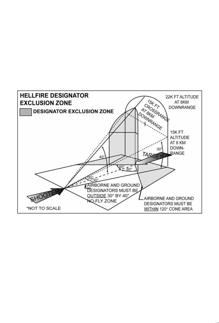
4. Hellfire Designator Exclusion Zone
a. Within 30-degrees of the shooter aircraft’s line of fire (in the designator
exclusion zone), there is a possibility that the missile may track and impact an
obstruction (e.g., trees, grass, or hills) near the designator operator if it is
accidentally illuminated by the laser beam.
b. The designator shall have a clear, unobstructed line of sight to the target. Take
care to ensure designator line of sight is unobstructed across the entire path of a
moving target during the time of missile flight to impact.
c. Airborne designators must ensure that they are either over ground conditions
which do not create dust or are at altitudes where rotor downwash does not
create dust.
Figure 18. Hellfire Designator Exclusion Zone
86 FM 3-09.32/MCRP 3-16.6A/NTTP 3-09.2/AFTTP(I) 3-2.6 Dec 2007
Appendix D:Fire Support Coordination Measures and Airspace
Coordinating Measures
Note: For detailed descriptions of fire support coordination measures
(FSCMs) and airspace coordinating measures (ACMs), see JP 3-09,
Joint Fire Support, and JP 3-52, Joint Doctrine for Airspace Control in
the Combat Zone.
1. Permissive and Restrictive Fire Support Coordination Measures
Commanders employ permissive and restrictive FSCMs. With the exception of
the fire support coordination line (FSCL), permissive measures normally require
no further detailed coordination for the engagement of targets with conventional
means. Coordination of attacks beyond the FSCL is especially critical to
commanders of air, land, and special operations forces. In exceptional
circumstances, the inability to conduct this coordination will not preclude the
attack of targets beyond the FSCL. However, failure to do so may increase the
risk of fratricide and could waste limited resources. Restrictive measures impose
requirements for specific coordination before engagement of targets with the
primary purpose of safeguarding an asset.
a. Free Fire Area (FFA). A specific area into which any weapon system may fire
without additional coordination with the establishing headquarters. It is used to
expedite joint fires and to facilitate emergency jettison of aircraft munitions.
b. Coordinated Fire Line (CFL). A line beyond which conventional indirect
surface joint fire support means may fire at any time within the boundaries of the
establishing headquarters without additional coordination. The purpose of the
CFL is to expedite the surface-to-surface engagement of targets beyond the CFL
without coordination with the ground commander in whose area the targets are
located.
c. Restrictive Fire Line (RFL). A line established between converging friendly
forces that proh bits joint fires or their effects across that line without coordination
with the affected force. The purpose of the line is to prevent fratricide and
duplication of engagements by converging friendly forces.
d. No-fire Area (NFA). An NFA is an area designated by the appropriate
commander into which fires or their effects are prohibited. There are two
exceptions:
(1) When the establishing HQ approves joint fires within the NFA on a mission by
mission basis.
(2) When an enemy force within the NFA engages a friendly force and the
engaged commander determines there is a requirement for immediate protection
and responds with the minimal force needed to defend the force.
e. Restrictive Fire Area (RFA). An area in which specific restrictions are imposed
into which fires that exceed those restrictions will not be delivered without
coordination with the establishing headquarters. The purpose of the RFA is to
regulate joint fires into an area according to the stated restrictions.
Dec 2007 FM 3-09.32/MCRP 3-16.6A/NTTP 3-09.2/AFTTP(I) 3-2.6
87
f. Airspace Coordination Area (ACA). A three-dimensional block of airspace in a
target area, established by the appropriate ground commander, in which friendly
aircraft are reasonably safe from friendly surface fires. The airspace coordination
area may be formal or informal.
2. Maneuver Control Measures
Unit Boundaries. A boundary is a line that delineates surface areas for the
purpose of facilitating coordination and deconfliction of operations between
adjacent units, formations, or areas (JP 3-0, Joint Operations). Direct fires may
be employed across boundaries without clearance at specific point targets that
are clearly and positively identified as enemy. Indirect fires may not be employed
across boundaries without receiving clearance from the unit into whose AO the
fires will impact.
3. Battlefield Coordination Line
a. The BCL is an exclusive Marine Corps FSCM, similar to a FSCL, which
facilitates the expeditious attack of targets with surface indirect fires and aviation
fires between this measure and the FSCL. To facilitate air-delivered fires and
deconflict air and surface fires, an ACA will always overlie the area between the
BCL and the FSCL.
b. BCL location is graphically portrayed on fire support maps, charts, and
overlays by a solid black line with the letters “BCL” followed by the establishing
headquarters in parentheses above the line and effective date-time group below
the line. BCL is not currently supported by automated systems for depiction.
88 FM 3-09.32/MCRP 3-16.6A/NTTP 3-09.2/AFTTP(I) 3-2.6 Dec 2007

Table 25. Permissive Measures
Coordination Required for Fires?
Establishing
Short of / within measure
Beyond measure
Name
Notes
Headquarters (HQ)
Surface to
Air to
Surface to
Air to
Surface
Surface
Surface
Surface
A specific area into
Normally DIV or
which any weapon
HHQ. However,
system may fire w/o
it can be established
additional
FFA
No
No
N/A
N/A
by any Commander
coordination with
who owns the ground
establishing HQ.
such as BDE.
Normally on
identifiable terrain.
Normally established
Yes
Purpose is to
by BDE or DIV - can
IAW other
expedite surface to
CFL
Yes
Yes
No
be consolidated by
control
surface attack
DIV.
measures
beyond CFL.
No
No
No
Yes
BCL
MAGTF
CFL
Only if
Only if
Note 1.
HHQ
Dependent
IAW ACA
IAW ACA

Table 25. Permissive Measures
Coordination Required for Fires?
Establishing
Short of / within measure
Beyond measure
Name
Notes
Headquarters (HQ)
Surface to
Air to
Surface to
Air to
Surface
Surface
Surface
Surface
Land or Amphibious
No, CFL
Yes
Yes
FSCL
No
Does not divide AO
Forces Commander
Dependent
Establish HQ
HHQ
1Aviation may str ke any target within the USMC AO beyond the BCL and short of the FSCL without further
coordination, including targets in an adjacent Marine commander’s zone between the BCL and FSCL. Before
firing, the ground commander should coordinate with the DASC if surface-delivered fires will violate ACAs
associated with the BCL.
AO - area of operations, BDE - brigade, DIV - division, HHQ - higher headquarters, MAGTF - Marine air-to-
ground task force.

Table 26. Restrictive Measures
Coordination Required for Fires?
Establishing
Name
Headquarters
Short of / Within Measure
Beyond Measure
Notes
(HQ)
Surface to
Air to
Surface to
Air to
Surface
Surface
Surface
Surface
Established between con-
RFL
HHQ of
Yes;
Yes;
verging forces. Prevents
converging
N/A
N/A
affected
affected
fratricide and duplication of
forces
force
force
attacks. Located on
identifiable terrain if possible.
Prohibits all fires or effects into the area with the
NFA
Any HQ
Located on identifiable terrain
following exceptions:
or by radius from established
- Establishing HQ approves fires or effects on a
point.
mission-by-mission basis.
- Enemy forces inside NFA engage friendly forces
and engaged commander requests fires.
Specifies certain restrictions on fires into the area
Located on identifiable terrain
BN HQ or
RFA
- Fires which violate restriction prohibited
or by radius from established
higher
- Fires which do not violate restriction allowed
point.
Airspace
Defined by min/max altitude,
ACA
Control
length, width, and effective
Formal
Authority
date time group.
Yes
Yes
N/A
N/A
Air and surface fires
ACA
Any HQ
separated by lateral, altitude,
Informal
lateral and altitude, or time.

4. Integration Techniques
There are numerous separation techniques used by JTACs in the field. There is
no one preferred technique, but JTACs should always plan on the one that allows
for the most firepower on the target. If at all possible, never shut off artillery
when flying CAS or vice versa. In many cases providing the artillery information
to the aircrew and allowing the aircrew to determine a lateral or altitude
deconfliction measure is most effective. The same logic can be applied to
deconflict UAs and manned aircraft.
Table 27. Integration Techniques
CAS target same
CAS target
CAS target distant
Parameters
as or near surface
along gun-
from surface target
target
target line
Time /
High / Medium
Time / Altitude
Time / Altitude /
Altitude
Altitude Attack
Separation
Lateral Separation
Separation
Time /
Low / Very Low
Time / Altitude or
Time Separation
Altitude
Altitude Attack
Lateral Separation
Separation
Figure 19. Artillery Close Air Support Lateral Separation
92 FM 3-09.32/MCRP 3-16.6A/NTTP 3-09.2/AFTTP(I) 3-2.6 Dec 2007

Figure 20. Artillery Close Air Support Altitude Separation
5. Common Geographic Reference System and Global Area Reference
System
Both the CGRS and GARS are administrative measures used to clearly define
two-dimensional geographical areas for battlespace coordination, deconfliction,
and synchronization. The CGRS / GARS defined cells themselves are not
FSCMs, ACMs, or maneuver control measures, but simply a common reference
system that complements joint fire support and / or airspace control systems and
measures. However, these systems may be used to define lateral ACM and
FSCM boundaries. See theater-specific standard operating procedures for using
CGRS. GARS has been established as the Department of Defense-approved
reference system. Until it is fully implemented by all Services and in all theaters,
CGRS might still be referenced.
NOTE: The CGRS or GARS should not be confused with kill box
methodology. For kill box operations, refer to FM 3-09.34 / MCRP 3-
25H / NTTP 3-09.2.1 / AFTTP(I) 3-2.59 Multi-Service Tactics,
Techniques, and Procedures for Kill Box Employment and theater-
specific SOP.
Dec 2007 FM 3-09.32/MCRP 3-16.6A/NTTP 3-09.2/AFTTP(I) 3-2.6
93

Figure 21. Common Geographic Reference System Example
Figure 22. Global Area Reference System Example
94 FM 3-09.32/MCRP 3-16.6A/NTTP 3-09.2/AFTTP(I) 3-2.6 Dec 2007
Appendix E:Aircraft-delivered Munitions Descriptions
1. General Purpose Munitions
a. All general purpose (GP) munitions are similar in construction and vary only
in size and weight with a streamlined cylindrical body. Conical fins are
designed for low drag (LD) releases. Retarding fins / air inflatable retarder
(AIR) are designed for high drag (HD) releases.
b. 500-pound LD / HD
(1) Mk-82: Selectable HD / LD when fit with AIR or retarding fins.
- Effects: blast, fragmentation, and limited cratering.
(2) BLU-111: Improved, thermally protected GP bomb.
- Effects: blast, fragmentation, and limited cratering.
(3) BLU-126 - 500 lb thermally protected low collateral damage bomb
(LCDB) (20% explosive fill BLU-111)
- Effects: blast and limited fragmentation.
c.
1000-pound LD / HD
(1) Mk-83: Selectable HD / LD when fit with AIR or retarding fins.
- Effects: blast, fragmentation, and cratering.
(2) BLU-110/B: Improved, thermally protected GP bomb.
- Effects: cratering and hard target penetration.
d. 2000-pound LD / HD
(1) Mk-84: Selectable HD / LD when fit with AIR or retarding fins.
- Effects: blast, fragmentation, and cratering.
(2) BLU-109/B: Penetrator, improved protected GP bomb.
- Effects: cratering and hard target penetration.
(3) BLU-117: Improved, thermally protected GP bomb.
- Effects: blast, fragmentation, and cratering.
e. Other weights:
(1) BLU-113 Penetrator bomb: 4,400-pound improved GP bomb.
- Effects: cratering and hard target penetration.
(2) M-117: 750-pound GP bomb with very thin bomb casing.
- Effects: more blast and less fragmentation than other GP bombs.
(3) M-117R: Selectable HD / LD by means of retarding tail assembly.
2. Guided Bombs
a. IAMs are accurate (near precision), all weather, INS / GPS-guided bombs
for use against stationary targets. Multiple IAMs can be dropped on
different targets in a single pass. Effects: blast / fragmentation or cratering
with a delayed fuze (Mk-83/84 bomb body) or hard target penetrator with
(BLU-109/110 bomb body).
(1) GBU-38 JDAM w/ Mk-82 bomb body
(2) GBU-38 (v)4/B JDAM w/BLU-126 bomb body (USN)
(3) GBU-32 (v)2/B JDAM w/ Mk-83 bomb body (USN / USAF)
(4) GBU-32 (v)4/B JDAM w/ BLU-110 bomb body (USN)
(5) GBU-31 (v)1/B (USAF) or (v)2/B (USN) JDAM w/ Mk-84 bomb body
(6) GBU-31 (v)3/B (USAF) or (v)4/B (USN) JDAM w/ BLU-109 bomb body
(7) GBU-39 / Small Diameter Bomb (SDB). An accurate, extended range
all-weather, 250-pound class, GPS guided munition. It is effective
Dec 2007 FM 3-09.32/MCRP 3-16.6A/NTTP 3-09.2/AFTTP(I) 3-2.6
95
against fixed or stationary targets and has limited penetration
capabilities. Multiple weapons can be dropped on different targets in a
single pass. As a standoff weapon, the SDB may climb in altitude after
release to assume its glide profile. The weapon’s flight path may
present deconfliction problems depending on the ACAs in place.
- Effects: blast / fragmentation or penetration.
b. Paveway II - Laser-guided, free-fall weapon. Laser codes are pre-flight
selectable (code 1511-1788). These weapons can be fuzed for
instantaneous (fragmentation) or delayed (cratering) detonation.
(1) GBU-12 uses an Mk-82 bomb body.
(2) GBU-16 uses an Mk-83 or BLU-110 bomb body.
(3) GBU-10 uses an Mk-84 or BLU-109 bomb body.
(4) GBU-15/EGBU-15 - TV- or IR-guided, automatically or manually by the
weapon system operator (WSO). Mk-84 or BLU-109 body. Effects:
same as Mk-84/BLU-109. The hybrid EGBU-15 incorporates GPS / INS
guidance providing precision adverse weather capability for autonomous
or man-in-the-loop deliveries.
(5) GBU-51/B - Laser-guided, free-fall GBU-12 kit with a BLU-126 LCDB
body.
c. Paveway III - Low-level, laser-guided, maneuverable free-fall weapon.
Uses Mk-84 (GBU-24), BLU-109 (GBU-24A) or BLU-116 advanced unitary
penetrator (AUP) bomb bodies. AUP is a 2,000-lb class penetrator bomb
with twice the penetration capability of the BLU-109. Used only in GBU-
24C/B (USAF) and GBU-24D/B (USN).
- Effects: cratering and hard target penetration. GBU-24E/B adds GPS /
INS guidance to allow adverse weather capability with BLU-109 bomb
body. Can be released from very low or very high altitudes. Can be
released below a low overcast (3,000-4,500’ AGL) if the correct mode
switches have been set prior to takeoff. Can be launched without laser
signal acquisition. Effects: same as Mk-84.
d. Hybrid weapons - Guided by laser and / or GPS-aided INS.
(1) GBU-12F/B Dual-mode LGB (DMLGB) - 500-lb bomb with LASER and
IAM capability.
(2) GBU-28 (GBU-37) - Laser-guided (GPS) BLU-113. 4,700- b weapon
used for hard target penetration.
(3) GBU-52/B DMLGB - similar to GBU-12F/B but with BLU-126 LCDB
body.
(4) GBU-54 Laser JDAM (LJDAM) - a multi-mode 500-lb weapon that
includes guidance via GPS with coordinate refinement through laser
updates. It uses a GBU-38 tail kit with the addition of a laser kit attached
to the nose and can be used in legacy mode as GPS only with no
degradation in capability. LJDAM is capable of hitting high speed
moving targets. Target heading and velocity can be programmed into
the weapon to generate an impact point in front of the target. At 4.5 km,
if laser energy is present, the LJDAM will calculate new coordinates
based on the movement of the laser. The weapon will then guide to the
updated lead point. LJDAM is a coordinate seeking weapon and does
not guide on laser energy like an Enhanced PWII. It continuously
96 FM 3-09.32/MCRP 3-16.6A/NTTP 3-09.2/AFTTP(I) 3-2.6 Dec 2007
calculates new coordinates based on the laser spot. Therefore, if the
weapon loses laser energy it will guide on the last known coordinates.
3. Guided Missiles
a. AGM-65 (Maverick) - Tactical, air-to-surface guided missile designed for
high probability of strike against tanks and a variety of tactical targets,
including moving vehicles. Maverick seeker is locked on to the target prior
to release and guides autonomously (except AGM-65E), providing standoff
ranges of up to 10 nm.
(1) Guidance: TV (A,B,H,K); IR (D,F,G2); Laser (E).
(2) Warheads: 125 lbs. shaped charge jet and blast (A,B,D,H) or 300-lbs.
penetrator / blast-fragmentation (E, F, G2, K).
b. AGM-84E Stand-Off Land Attack Missile (SLAM)-AGM-84H (SLAM-
Expanded Range [ER]) - An intermediate range (over 150 nm for SLAM-
ER) missile designed to provide day, night, and adverse weather precision
strike capability against land targets and ships in port. The SLAM uses an
inertial navigation system with GPS, infrared terminal guidance, and is fitted
with a titanium warhead for better penetration.
c. AGM-88 High-speed Antiradiation Missile (HARM). A supersonic air-to-
surface tactical missile designed to seek and destroy radar-equipped air
defense systems. The AGM-88 can detect, attack, and destroy a target with
minimum aircrew input. (Range > 40 nm).
d. AGM-114 (Hellfire) - Solid propellant laser or radar frequency guided anti-
armor missile. Can also be used against buildings and field fortifications.
Hellfire variants include shaped charge, blast fragmentation, and metal
augmented charge warheads. Max effective range: 8,000 meters. Min
range is based on employment technique, but 500 meters should be used
as a guide. Radar frequency Hellfire (Longbow) is all weather capable.
(1) A/B/C/F/K - Shaped Charge Warhead - Designed for use against
armored vehicles.
(2) L - Shaped Charge Warhead - Radar guided compatible with Apache
Longbow.
(3) M - Blast-Fragmentation Warhead - Designed for personnel and thin-
skinned vehicles.
(4) N - Thermobaric Warhead - Designed to kill by overpressure in confined
spaces.
(5) P - Shaped Charge Warhead - AGM-114K designed for use on MQ-1
and MQ-9.
e. AGM-130 - Rocket-powered version of GBU-15. Standoff range between
15 and 40 nm. Midcourse guidance version uses GPS for guidance (WSO
is still able to steer the weapon during terminal guidance for pinpoint
accuracy).
f. AGM-154 JSOW. A low-observable, all weather 1,000- b class family of
stand off air-to-ground glide weapons. Modular payload assembly to attack
armored and light-armored vehicle columns, surface-to-air targets, and
personnel.
(1) Guidance: AGM-154A & B-INS/GPS
AGM-154C (Navy only) INS / GPS w/ IR Seeker.
Dec 2007 FM 3-09.32/MCRP 3-16.6A/NTTP 3-09.2/AFTTP(I) 3-2.6
97
(2) Warheads: AGM-154A = 145 BLU-97 bomblets
AGM-154B = 6 BLU-108s (24 skeets)
AGM-154C = BLU-111 or BROACH
(3) Range: 15nm at low altitude, >40nm at high altitude.
g. AGM-158A Joint air-to-surface stand-off missile (JASSM). A precision
cruise missile designed for launch from outside area defenses to kill hard,
medium-hardened, soft, and area type targets. Guidance: Imaging, Infrared
Radar. 2,000-lb Unitary Warhead.
h. BGM-71 Tube-launched, Optically tracked, Wire-guided (TOW) Missile.
Solid propellant, wire-guided, anti-armor missile. Range: min. 500 m; max
3750 m; max time of flight: 21.5 sec.
4. Guns
a.
7.62 Mini-Gun - Up to 6,000 rounds / min. target practice (TP), armor
piercing (AP), tracer.
b. 50 Cal - 1,150 to 1,250 rounds / min. TP, AP, armor piercing incendiary
(API), and tracer.
c.
20mm - 750 to 850 rounds/min. AP, HE, and incendiary.
d. 20mm Gatling - 2,500-6,000 rounds / min. TP, high explosive incendiary
(HEI), API, target practice tracer (TPT), HEIT, PELE [penetrator with
enhanced lateral efficiency].
e. 25mm Gatling (GAU-12) - 3,600-4,200 rounds / min (AV-8B) or 1,800
rounds / min (AC-130) TP, HEI, API, TPI, or HEIT.
f.
30mm (M230 cannon AH-64) - TP, high explosive dual purpose (HEDP)
(Shaped charge and fragmentation.) Target types: personnel, material, and
light armor.
g. 30mm Gatling (GAU-8) - 3,900 rounds / min. 1.5-lb projectile TP, HEI, API
on A-10 (can fire 1,174 rounds in 10, 2-second bursts).
h. 30mm (M44 on AC-130) - 200 rounds / min, PGU-13/B HEI.
i.
40mm (AC-130) - 100 rounds / min. HEI, API, high explosive incendiary-
plugged (HEI-P). Target types: personnel undercover and all light vehicles.
Fired from 4,500 ft AGL min altitude to 18,000 ft AGL max altitude.
j.
105mm (AC-130) - 10 rounds / min. HE and HE/High Fragmentation,
Proximity. Target types: personnel, light vehicles, buildings. Fired from
4,500 ft AGL min altitude to 18,000 ft AGL max altitude.
5. Rockets
a. 2.75” Rocket Warheads
(1) Mk Mk-67 mod 1—Smoke Red Phosphorous (RP).
(2) Mk-67 mod 0—Smoke White Phosphorous (WP).
(3) M-151—(10-lb. HE). Fuses: point detonating (PD), proximity (P), time
delay (TD); primary fragmentation against personnel, material, and light
armor.
(4) M-156—WP. Used for target marking.
(5) M-229—(17-lb HE). Same as M-151.
(6) M-257— Overt illumination.
(7) M-261— Multi-purpose submunition (MPSM), Fuse TD; 9 shape charge /
fragmentation submunitions; AP, anti-material, and light armor.
98 FM 3-09.32/MCRP 3-16.6A/NTTP 3-09.2/AFTTP(I) 3-2.6 Dec 2007
(8) M-278 - Delivers covert (Near IR / NVG) illumination.
(9) M-255E1—Flechette for antipersonnel.
(10) WDU-4A/A—Flechette for antipersonnel (USMC).
(11) WTU-1/B—TP. A practice M-151.
b. 5.00” Rocket Warheads.
(1) Mk-63 mod 0—Fuzes: PD, P, TD; HE-fragmentation; AP, anti-material.
(2) Mk-24 GP—Fuses: PD, P, TD; fragmentation, AP, anti-material, and light
armor.
(3) Mk 32 Antitank (AT)/AP—Fuses: PD, P, TD; for use against personnel.
(4) Mk 34 Mod2 RP—Fuses: PD, P, TD; smoke.
(5) MK 84—Chaff rocket for use against radar threats
(6) Mk 6/24/32 and WTU-11/B practice rounds - Inert practice variants.
6. Cluster Munitions
a. Mk-20 and CBU-99/100 cluster munitions (USN) - Excellent weapon
against armor, personnel, artillery, etc. Dispenses 247 Mk 118 mod 0/1
bomblets in an oval pattern. Bomblet density and pattern size vary with
release parameters.
b. CBU-78 GATOR (USN) - Rockeye dispenser loaded with 60 submunition
mines. 45 BLU-91/B antitank and 15 BLU-92/B anti-personnel mines are in
each weapon. Submunitions must be set to one of three self-destruct times:
T1 (3.2-4.0 hours), T2 (38.2-48.0 hours), and T3 (288-360 hours).
c. CBU-87/B Combined Effects Munitions (CEM) - Excellent weapon against
armor, personnel, artillery, etc. Dispenses 202 BLU-97 bomblets with a
shaped charge for armor, steel-scored liner for fragmentation, and
incendiary ring.
(Note: Dispersion is an oval with density and size of the
area covered dependent upon release parameters and spin rates.)
d. CBU-89/B GATOR - SUU-64 Tactical Munitions Dispenser loaded with a
mix of 72 BLU-91/B anti-armor and 22 BLU-92/B anti-personnel mines with
preset self-destruct time.
(Note: Dispersion varies from circular at high
altitudes to linear at low angles.)
e. CBU-97/B Sensor-Fuzed-Weapon (SFW) - SUU-64 with an airbag
dispensing system and 10 BLU-108/B submunitions. Provides multiple kills
per pass capability against tanks, armored vehicles, artillery, armored
personnel carriers (APCs), and support vehicles. This cluster weapon is
dropped over an area with armor. The fuze sensors detect heat and fires
down at the engine of the armored vehicle.
f. CBU-103 to 105 Wind Corrected Munitions Dispenser (WCMD) - All
weather, INS-guidance tail kit for CBU. The tail kit inertially steers the
munition from a known release point to precise target coordinates while
compensating for launch transients, winds aloft, surface winds, and adverse
weather.
(1) CBU-103 = CBU-87/B + WCMD tail kit.
(2) CBU-104 = CBU-89/B + WCMD tail kit.
(3) CBU-105 = CBU-97/B + WCMD tail kit.
g. CBU-107 Passive Attack Weapon - 1000-lb CBU-87 canister loaded with a
mix of inert kinetic energy penetrators (364 large, 1004 medium, 2406 small
Dec 2007 FM 3-09.32/MCRP 3-16.6A/NTTP 3-09.2/AFTTP(I) 3-2.6
99
rods) fuzed with an FZU-39/B proximity sensor and equipped with a WCMD
tail kit.
h. PDU-5 Leaflet Dispenser (USN) - CBU-100 munition body loaded with
leaflet materials for psychological operations purposes.
i. BL-755 - European munitions loaded with 147 anti-armor submunitions.
Designed for low-altitude, low-angle deliveries against armor. (Note:
Dispersion is a rectangular pattern).
7. Illumination Flares
a. LUU-1/B, 5B, 6D (target marking flares)—Designated for a 30-minute burn
time on the ground, providing a colored flame. LUU-1 burns red, LUU-5
burns green, and LUU-6 burns maroon.
b. LUU-2A/B - B/B Flare—Parachute flare with a 4-minute burn time at an
average of 1.6 million candle power.
c. LUU-19B - A/B Covert Flare—Parachute flare with a burn time of
approximately 7 minutes in the IR spectrum.
d. M257—2.75-inch rocket delivers overt (visible) illumination that provides 1
million candlepower for an average 120-sec. burn time.
e. M278—2.75-inch rocket delivers IR (.7 - 1.1 microns) illumination that
provides 180 seconds of coverage.
8. Incendiary Munitions
Mk-77 Fire Bombs (USN) - 500 lbs class incendiary munition filled with 63
gallons of hydrocarbon fuel and 44 pounds of dry gelling mixture. This weapon is
effective against personnel, light-skinned vehicles, and stockpiled stores.
9. Inert and Practice Munitions
a. BDU-33—25-lb practice bomb with spotting charges.
b. BDU-48/B—Practice bomb that simulates Mk-82 HD ballistics. (Similar to
Mk-106.)
c. BDU-45—Mk-82 inert 500- b practice bomb (USN).
d. BDU-50—Mk-82 inert 500- b practice bomb (USAF).
e. BDU-56—Mk-84 inert 2,000-lb practice bomb.
f. Mk-83 (inert) - Mk-83 inert 1,000-lb practice bomb (USN).
g. Mk-106—Practice bomb simulating HD ballistics with spotting charge.
h. Mk-76—Navy version of BDU-33.
i. LGTR-Laser guided training round with 12 preflight selectable laser
guidance codes. Ballistics are similar to GBU-12.
10. Common United Kingdom Weapons
a. Paveway II (PWII) - Laser guided free-fall weapons. Laser codes are pre-
flight selectable (code 1511-1788). These weapons can be fuzed for
instantaneous (fragmentation) or delayed (cratering) detonation, preset on
the ground. The bomb is a 1000-lb class weapon, slightly broader than the
US Mk-83.
b. Enhanced Paveway II (EPWII) - Hybrid version of the PWII. Weapon can
be released in legacy (no GPS) or GAINS mode. If released using the GPS
(GAINS) mode, then the target position can be refined by the use of the
100 FM 3-09.32/MCRP 3-16.6A/NTTP 3-09.2/AFTTP(I) 3-2.6 Dec 2007
laser - the seeker will prioritize a valid laser return over the GPS position.
Laser codes are pre-flight selectable (1511-1788). These weapons can be
fuzed for instantaneous (fragmentation) or delayed (cratering) detonation.
Carried by Tornado GR4, Harrier GR7 and Typhoon. The E prefix means
“enhanced.”
c. Enhanced Paveway II Plus, (EPWII+) - A Paveway IV seeker on a PWII
bomb body and tail. Introduced as an interim for PWIV, it has the ability to
define impact conditions in flight and has a greater launch acceptable range
(LAR). Otherwise similar to EPWII, still a 1000-lb class weapon. Carried on
the Harrier GR9.
d. Paveway III (PWIII) - Similar to the GBU-24 (BLU-109 warhead). Carried
on Harrier and Tornado.
e. Enhanced Paveway III (EPWIII) - Enhanced version of the PWIII with the
addition of a GPS guidance kit. EWPIII only carried on Tornado GR4.
f. Paveway IV (PWIV) - Fully programmable in-flight for impact angle,
azimuth, fuze settings (impact, delayed, airburst) 500-lb class weapon.
Large LAR, for use with Tornado GR4 and Harrier GR9.
g. 540-lb bomb - Unguided freefall weapon similar to US Mk-82. Can be set
to retard or freefall before flight. Fuzed with a 960 (standard UK fuze),
which can be set to impact, delay, or airburst. Carried on the Harrier GR7/9
only.
h. 1000-lb bomb - Unguided freefall weapon similar to US Mk-83. Can be set
to retard or freefall before flight. Fuzed with 960 (standard UK fuze), which
can be set to impact, delay, or airburst. Carried on the Harrier GR7/9,
Tornado GR4, and Typhoon.
i. CRV-7 Rocket - A mach 4 rocket, similar to the 2.75” used in the US. Pods
are designated “Training” (reusable 6-shot pod) and “Operational”
(disposable 19-shot pod). Warhead types are kinetic energy penetrator or
high explosive semi-armor piercing, with a time delay.
j. Maverick - AGM-65 G2 and JX (IR and CCD variants). Minor differences to
the US equivalents. Carried on the Harrier only.
k. Brimstone - Millimeter-wave radar, antiarmor missile. 3 missiles per
launcher (one launcher with 3 missiles known as a weapon.) Carried on the
Tornado GR4 with 4 weapons and on the Harrier in with 2 or 4 weapons
standard. Very low collateral damage weapon.
Dec 2007 FM 3-09.32/MCRP 3-16.6A/NTTP 3-09.2/AFTTP(I) 3-2.6
101

Table 28. Recommended Target-Weapons Pairings for Ordnance
Targets
Recommended Ordnance
Maverick, Hellfire K, TOW, LGB (GBU-10/12/16), GBU-39, JDAM or GP
Armored Vehicles: tanks, APCs, and
bomb (with inst. Fuze), CBU-87 CEM, CBU-89 Gator (mine), CBU-97 SFW,
mobile assault guns
CBU-103/104/105 (WCMD), JSOW, 30 mm (AP/HEI), SLAM-ER
Area denial and channelization
CBU-89/104 (mine)
Maverick, GP bomb, GBU-39, JDAM, JSOW, Hellfire, TOW, 20/30 mm
Soft targets: trucks, radar, aircraft
guns (AP/HEI), 25/40/105 mm gun (AC-130), CBU-87/103 (CEM), 2.75”
parked in open, etc.
rockets (w/ M261, M229, M151), SLAM-ER
Personnel:
GP bomb, GBU-39, JDAM, 20/25/30/40/105 mm, CBU-87/103 (CEM)
In the open
2.75” rockets (M229, M151, M261, M255E1/WDU-4A/A Flechette)
In fighting / prepared positions
GP bomb, GBU-39, JDAM, 2.75” rockets (w/ M261, M299, M151)
GP bomb, GBU-39, JDAM, 20/25/30/40 mm, 2.75” rockets (w/ M229,
Under light cover
M151), CBU-87/103 (CEM)
GP bomb or JDAM (w/ BLU-109/110), GBU-39, GP bomb with steel nose
Under heavy cover (concrete bunker)
plug, LGB (GBU-10/24/28), Maverick, (E)GBU-15, AGM-130
GP bomb or JDAM, LGB (GBU-10/24/28), Maverick, Enhanced (E)GBU-15
Buildings
AGM- 130/158, Hellfire M/N, 2.75” rockets (w/ M229, M151), SLAM-ER

Table 28. Recommended Target-Weapons Pairings for Ordnance
Targets
Recommended Ordnance
CBU-87/97/103/105, JSOW, GP bomb, GBU-39, JDAM, LGB (GBU- 10/12/16/24),
Artillery, AAA, Rocket Launcher:
Maverick, Hellfire, TOW, (E)GBU-15, AGM-130, 2.75” rockets (w/ M255E1/WDU-4A/A
In the open
Flechette, M261, M299, M151), 30/ 40 mm gun
CBU-97, GP bomb, GBU-39, JDAM, LGB (GBU-10/12/16/24), Maverick, Hellfire,
In revetment
30 mm, (E)GBU-15, AGM-130, 2.75” rockets (w/ M261, M229, M151)
GP bomb, JDAM, LGB (GBU-10/12/16/24), Maverick, Hellfire, (E)GBU- 15, AGM-130,
In covered position
2.75” rockets (w/ M229, M151)
HARM, CBU-87/97/103/105, JSOW, GBU-39, JDAM, Hellfire, GP bomb, LGB (GBU-
SAM Site /
10/12/16/24), TOW, (E)GBU-15, AGM-65/130/158, 20/25/30/40/105 mm, 2.75” rockets
Surface-to-Surface Missile Site
(w/ M261, M229, M151), SLAM-ER
Moving Targets
Maverick, Hellfire, Laser JDAM, GBU-12/51, 20/30 mm guns (strafe)
AGM - air-to-ground missile HEI - high explosive incendiary
AP - armor piercing JDAM - Joint Direct Attack Munition
CBU - cluster bomb unit JSOW - joint stand-off weapon
CEM - combined effects munition LGB - laser-guided bomb
E - enhanced SFW - sensor-fused weapon
GBU - guided bomb unit SLAM-ER - stand-off land attack missile - expanded range
GP - general purpose TOW - tube-launched, optically tracked, wire guided
HARM - high-speed antiradiation missile WCMD - wind corrected munitions dispenser
This page intentionally left blank
104 FM 3-09.32/MCRP 3-16.6A/NTTP 3-09.2/AFTTP(I) 3-2.6 Dec 2007
Appendix F: Risk-estimate Distances
Risk-estimate distances allow the supported commander to estimate the risk to
friendly troops from friendly attack. When ordnance may be a factor to the safety
of friendly troops, aircraft attack heading should be parallel to the friendly forces.
This mitigates the risk from long or short deliveries. Risk-estimate distances
allow the supported commander to estimate the risk in terms of the percent of
friendly casualties that may result from fires against an enemy threat along the
forward line of own troops (FLOT). Friendly forces outside the 0.1% probability
of incapacitation (PI) distance are still subject to weapons fragments, but at a
lower risk. Commanders must carefully weigh the choice of ordnance, accuracy,
and proficiency of the aircraft/firing unit in relation to the risk of fratricide. Taking
steps to protect friendly soldiers (e.g., prone, behind cover) can reduce the risk.
Risk-estimate distances are based on fragmentation and blast patterns.
Warning: 0.1% probability of incapacitation numbers are for combat
use only during “danger close” situations and are not minimum safe
distances for peacetime training.
1. Danger Close
a. In CAS, artillery, mortar, and naval gunfire support fires, danger close is the
term included in the method of engagement segment of a call for fire which
indicates that friendly forces are within close proximity of the target. The close
proximity distance is determined by the weapon and ammunition fired. Danger
close is not the same as minimum safe distance (MSD) or risk-estimate distance,
but allows the observer/controller to inform the FDC of the close proximity to
friendly forces. Aircraft ordnance delivery inside 0.1% PI distances will be
considered danger close. This is simply a warning and not a restriction to the
maneuver commander and the FDC to take proper precautions.
b. The supported commander must accept respons bility for the risk to friendly
forces when targets are inside 0.1% PI distance. The supported commander will
pass his/her initials to terminal controllers to pass to attacking aircraft, indicating
acceptance of the risk inherent in ordnance delivery inside the 0.1% PI distance.
The supported commander may pre-brief danger close authorization to his/her
JTAC / JFO / FO or Flight Lead / AMC. A call for fire constitutes consent to
danger close from the ground commander when pre-briefed.
c. Risk-estimate distances are defined as the distance in meters or feet from the
intended center of impact at which a specific degree of risk and vulnerability will
not be exceeded. The risk is usually expressed as the probability of
incapacitation, which is the probability that a soldier will suffer an incapacitating
injury. Percent PI value is less than or equal to 1 chance in 1,000.
Dec 2007 FM 3-09.32/MCRP 3-16.6A/NTTP 3-09.2/AFTTP(I)
105

2. Surface-to-surface Risk-estimate Distances
a. Danger close is usually 600 meters for canon and mortars and 750 meters
for naval gunfire. The creeping method of adjusting surface-to-surface fires
(no adjustment greater than 100 meters) will be used during danger close
missions.
b. Cannon risk-estimates were calculated using the following assumptions.
(1) Gun Target Line is perpendicular to the FLOT.
(2) An observer has adjusted the fires onto the target. Unadjusted FFE fires
may entail greater risk.
(3) The friendly troops are standing unprotected in the open, in winter
clothing and helmet, and on a line perpendicular to the line of fire.
Note: Friendly forces outside the PI distance may still be subject to
weapons fragments, but at a lower risk. Commanders and fire
supporters must carefully weigh the choice of ordnance and the
accuracy and proficiency of the firing unit in relation to the risk of
fratricide. Taking steps to protect friendly Soldiers (e.g. prone, behind
cover) can reduce the risk.
Table 29. Mortar Risk-estimate Distances
0.1% PI (meters/feet)
10% PI (meters/feet)
Item /
Description
1/3
2/3
Max
1/3
2/3
Max
System
Rng
Rng
Rng
Rng
Rng
Rng
60mm
100m/
150m/
175m/
60m/
65m/
65m/
M224
mortar
328’
492’
574’
197’
213’
213’
81 mm
165m/
185m/
230m/
75m/
80m/
80m/
M252
mortar
541’
607’
755’
246’
262’
262’
M120/
120 mm
150m/
300m/
400m/
100m/
100m/
100m/
M121
mortar
492’
984’
1312’
328’
328’
328’
Table 30. Cannon Risk-estimate Distances
0.1% PI (meters/feet)
10% PI (meters/feet)
Item /
Description
1/3
2/3
Max
1/3
2/3
Max
System
Rng
Rng
Rng
Rng
Rng
Rng
M102/
105mm
175m/
200m/
275m/
85m/
85m/
90m/
M119
Howitzer HE
574’
656’
902’
279’
279’
295’
M109/
155mm
200m/
280m/
450m/
100m/
100m/
125m/
M198/
Howitzer HE
656’
919’
1476’
328’
328’
410’
M777
M109/
155mm
280m/
300m/
475m/
150m/
180m/
200m/
M198/
Howitzer
919’
984’
1558’
492’
591’
656’
M777
DPICM
106 FM 3-09.32/MCRP 3-16.6A/NTTP 3-09.2/AFTTP(I) 3-2.6 Dec 2007

Table 31. Naval Gunfire Risk-estimate Distances
0.1% PI (meters/feet)
10% PI (meters/feet)
Item/
Description
1/3
2/3
Max
1/3
2/3
Max
System
Rng
Rng
Rng
Rng
Rng
Rng
450m/
450m/
600m/
210m/
225m/
250m/
Mk-45
5” / 54 gun
1476’
1476’
1969’
689’
738’
820’
Table 32. Tomahawk Land Attack Missile Risk-estimate Distances
Item/
Description
0.1% PI (meters/feet)
10% PI (meters/feet)
System
1000-lb unitary
TLAM
200m
/
656’
80m
/
263’
warhead
Note: TLAM risk-estimate distances are not range dependent.
3. Air-to-surface Risk-estimate Distances
Users must fully understand the assumptions used to develop these risk-
estimate distances. All values were calculated using the Joint Munitions
Effectiveness Manual Weaponeering System (JWS) version 1.1 software dated
31 Oct 2006 classified SECRET//NOFORN from the Joint Technical Coordinating
Group for Munitions Effectiveness.
The classified assumptions and conditions used to develop the risk-estimate
table are available on the ALSA classified website,
http://www.acc.af.smil.mil/alsa/jfire. Combining the online assumptions and/or
conditions with the risk-estimate numbers makes both sets of numbers classified.
The following risk-estimate table depicts a “worst-probable” scenario.
Table 33. Fixed-wing Risk-estimate Distances
Weapon
Description
0.1% PI (m/ft)
10% PI (m/ft)
Mk-82 LD contact
500-lb bomb
245 m
/
804’
105m
/
345’
Mk-82 LD1 airburst
500-lb bomb
300 m
/
984’
135m
/
443’
500-lb bomb/
Mk-82 HD contact
230 m
/
755’
130m
/
427’
retarded
Mk-82 HD1 airburst
500-lb bomb
280 m
/
919’
155m
/
509’
Mk-83 LD contact
1000-lb bomb
305 m
/
1001’
120m
/
394’
Mk-83 LD1 airburst
1000-lb bomb
340 m
/
1116’
145m
/
476’
1000-lb bomb/
Mk-83 HD contact
265 m
/
869’
160m
/
525’
retarded
1000-lb bomb/
Mk-83 HD1 airburst
315 m
/
1034’
175m
/
574’
retarded
Mk-84 LD1 contact
2000-lb bomb
315 m
/
1034’
110m
/
361’
Dec 2007 FM 3-09.32/MCRP 3-16.6A/NTTP 3-09.2/AFTTP(I)
107

Table 33. Fixed-wing Risk-estimate Distances
Weapon
Description
0.1% PI (m/ft)
10% PI (m/ft)
Mk-84 LD1 airburst
2000-lb bomb
380 m
/
1247’
140m
/
459’
2000-lb bomb/
Mk-84 HD contact
270 m
/
886’
165m
/
541’
retarded
2000-lb bomb/
Mk-84 HD1 airburst
355 m
/
1165’
180m
/
591’
retarded
CBU-872, CBU-892
CEM or GATOR
265 m
/
869’
180m
/
591’
CBU-103/104
CEM or GATOR
155 m
/
509’
90m
/
295’
(WCMD)
CBU-992/1002, Mk-202
Rockeye
230 m
/
755’
140m
/
459’
GBU-12
500-lb LGB
170 m
/
558’
50m
/
164’
GBU-51 contact
500-lb LCDB LGB
100 m
/
328’
35m
/
115’
GBU-16
1000-lb LGB
195 m
/
640’
75m
/
246’
GBU-10/24
2000-lb LGB
250 m
/
820’
70m
/
230’
GBU-38 contact
500-lb JDAM
185 m
/
607’
55m
/
180’
GBU-38 airburst
500-lb JDAM
230 m
/
755’
80m
/
263’
GBU-38(v)4 contact
500-lb LCDB JDAM
100 m
/
328’
35m
/
115’
GBU-32 contact
1000-lb JDAM
210 m
/
689’
75m
/
246’
GBU-32 airburst
1000-lb JDAM
275 m
/
902’
100m
/
328’
GBU-31 contact
2000-lb JDAM
265 m
/
869’
80m
/
263’
GBU-31 airburst
2000-lb JDAM
305 m
/
1001’
105m
/
345’
GBU-39 contact
250-lb SDB
135 m
/
443’
35m
/
115’
GBU-39 airburst (7’)
250-lb SDB
160 m
/
525’
40m
/
131’
GBU-39 airburst (14’)
250-lb SDB
180 m
/
591’
55m
/
181’
AGM-130
2000-lb TV guided
220m
/
722’
70m
/
230’
AGM-154
JSOW
170m
/
558’
100m
/
328’
AGM-158A
JASSM
210m
/
689’
55m
/
181’
AGM-65
Maverick (All)
95m
/
312’
35m
/
115’
2.75” Rockets med alt
365m
/
1198’
190m
/
623’
M151, M229, M2613
2.75” Rockets low alt
225m
/
738’
115m
/
377’
Zuni - Contact3
5” Rockets low alt
290m
/
951’
125m
/
410’
M61A1
20 mm gatling
60m
/
197’
35m
/
115’
GAU-12
25 mm gatling
55m
/
181’
30m
/
98’
GPU-5A, M230A1
30 mm gatling / chain
40m
/
131’
25m
/
82’
GAU-8 (A-10)
30 mm gatling
65m
/
213’
40m
/
131’
108 FM 3-09.32/MCRP 3-16.6A/NTTP 3-09.2/AFTTP(I) 3-2.6 Dec 2007

Table 33. Fixed-wing Risk-estimate Distances
Weapon
Description
0.1% PI (m/ft)
10% PI (m/ft)
25 mm
65m
/
213’
35m
/
115’
30 mm Mk 44
100m
/
328’
45m
/
148’
AC-130
40 mm
75m
/
246’
25m
/
82’
105 mm cannon
165m
/
541’
65m
/
213’
AGM-114 K
Hellfire
110m
/
361’
40m
/
131’
AGM-114 K2A
Hellfire
110m
/
361’
50m
/
164’
AGM-114 M
Hellfire
125m
/
410’
40m
/
131’
AGM-114 N
Hellfire
120m
/
394’
40m
/
131’
PW II / EPW24
UK PI Values
235m
/
771’
---
PW III / EPW34
UK PI Values
305m
/
1001’
---
AGM-654
UK PI Values
130m
/
427’
---
UK 540-lb bomb4
UK PI Values
200m
/
656’
---
UK 1000-lb bomb4
UK PI Value
240m
/
787’
---
CRV-7 - Single
UK PI Value
105m
/
345’
---
Rocket4
CRV-7 - Op Pod4
UK PI Value
125m
/
410’
---
See classified ALSA website for munitions profiles and assumptions.
1 Airburst fuzing (DSU-33).
4 Not recommended for use with troops in contact.
3 Fixed-wing only. See Table 34 for rotary-wing numbers.
4 UK - United Kingdom values shown for reference. No UK 10% PI available.
AGM - air-to-ground missile HD = high drag / air inflatable retarder (AIR)
alt - altitude LD - low drag
CBU - cluster bomb unit PW - Paveway
EPW - enhanced Paveway WCMD - wind corrected munitions dispenser
GBU - guided bomb unit
Warning: 0.1% / 10% Probability of Incapacitation numbers are for
combat use only during danger close situations and are not minimum
safe distances for peacetime training.
Warning: The risk-estimate distances listed in Tables 33 and 34 are
highly generalized and are valid only for the conditions specified in the
assumptions spreadsheet on the ALSA classified website
http://www.acc.af.smil.mil/alsa/jfire. Any change to these assumptions
may significantly increase the risk-estimate distances.
Dec 2007 FM 3-09.32/MCRP 3-16.6A/NTTP 3-09.2/AFTTP(I)
109

Table 34. Rotary-wing Risk-estimate Distances
Airframe /
0.1% PI
10% PI
Firing Range
Weapon
(meters/feet)
(meters/feet)
300m
20m
/
66’
15m
/
49’
0.50 cal1
500m
35m
/
115’
25m
/
82’
300m
75m
/
246’
30m
/
98’
Cobra / 20 mm (M56)
800m
85m
/
279’
50m
/
164’
500m
70m
/
230’
25m
/
82’
Apache / 30 mm (M789)
1000m
75m
/
246’
30m
/
98’
2.75” Rockets
300m
140m
/
459’
60m
/
197’
800m
160m
/
525’
80m
/
263’
M-151
1000m
180m
/
591’
90m
/
295’
2000m2
300m
/
984’
155m
/
509’
3000m2
405m
/
1329’
210m
/
689’
300m
145m
/
476’
70m
/
230’
800m
165m
/
542’
90m
/
296’
M-229
1000m
185m
/
607’
100m
/
328’
2000m2
305m
/
1001’
165m
/
542’
3000m2
410m
/
1346’
220m
/
722’
Hellfire Variants3
AGM-114 K2A
110m
/
361’
50m
/
164’
AGM-114 M
All Ranges
125m
/
410’
40m
/
131’
AGM-114 N
120m
/
394’
40m
/
131’
BGM-71 TOW
All Ranges
N/A
N/A
Anti-Tank
Rocket / gun assumptions: Running / diving fire with 5-20 degree dive angle
fired parallel to FLOT; 10 or 20 round gun burst or 2 round rocket burst; forward
flight.
1Non-exploding round (ball-type ammunition)
22000m and 3000m 2.75” rocket values for use by US Army aviation only.
3AGM-114 A/B/C/D/L/K variants will have risk-estimate distances smaller than
the variants listed above.
AGM - air-to-ground missile
cal - caliber
TOW - tube-launched, optically tracked, wire guided
110 FM 3-09.32/MCRP 3-16.6A/NTTP 3-09.2/AFTTP(I) 3-2.6 Dec 2007

Appendix G:General Information
1. Conversion Tables
Use the following table to calculate the number of minutes : seconds that it will
take an aircraft to go from the IP to the target at various ground speeds. Ground
speed (GS) is airspeed adjusted for winds at altitude. Table 36 converts meters
to feet for use on 9-Line briefings.
Table 35. Speed and Time Conversions
GS
nm/
8
9
10
11
12
13
14
15
(kts)
min
nm
nm
nm
nm
nm
nm
nm
nm
60
1
8:00
9:00
10:00
11:00
12:00
13:00
14:00
15:00
80
1.3
6:00
6:45
7:30
8:15
9:00
9:45
10:30
11:15
90
1.5
5:20
6:00
6:40
7:20
8:00
8:40
9:20
10:00
110
1.8
4:22
4:55
5:28
6:00
6:33
7:05
7:38
8:11
120
2
4:00
4:30
5:00
5:30
6:00
6:30
7:00
7:30
150
2.5
3:12
3:36
4:00
4:24
4:48
5:12
5:36
6:00
270
4.5
1:47
2:00
2:13
2:27
2:40
2:53
3:07
3:20
300
5
1:36
1:48
2:00
2:12
2:24
2:36
2:48
3:00
330
5.5
1:28
1:39
1:50
2:00
2:11
2:23
2:33
2:44
360
6
1:20
1:30
1:40
1:50
2:00
2:10
2:20
2:30
420
7
1:09
1:17
1:26
1:34
1:43
1:51
2:00
2:09
450
7.5
1:04
1:12
1:20
1:28
1:36
1:44
1:52
2:00
480
8
1:00
1:08
1:15
1:23
1:30
1:38
1:45
1:53
510
8.5
0:57
1:04
1:11
1:18
1:25
1:32
1:39
1:46
540
9
0:53
1:00
1:07
1:13
1:20
1:27
1:33
1:40
Aircraft Run-in Speeds
Aircraft GS (kts)
Aircraft
A/S (kts)
AH-1
60-120
AH-64
60-120
MH-60
60-120
AH-6
60-90
OH-58
60-90
A-10
270-350
B-1
480-540
AV-8B
420-480
B-2
400-460
F-15E/F-16
480-540
B-52
380-440
F/A-18
480-520
Dec 2007 FM 3-09.32/MCRP 3-16.6A/NTTP 3-09.2/AFTTP(I)
111

Table 36. Distance Conversion Table (1 meter = 3.28 feet)
Meters
Feet
Meters
Feet
Meters
Feet
25
82
525
1722
1025
3362
50
164
550
1804
1050
3444
75
246
575
1886
1075
3526
100
328
600
1968
1100
3608
125
410
625
2050
1125
3690
150
492
650
2132
1150
3772
175
574
675
2214
1175
3852
200
656
700
2296
1200
3936
225
738
725
2378
1225
4018
250
820
750
2460
1250
4100
275
902
775
2542
1275
4182
300
984
800
2624
1300
4264
325
1066
825
2706
1325
4346
350
1148
850
2788
1350
4428
375
1230
875
2870
1375
4510
400
1312
900
2952
1400
4592
425
1394
925
3034
1425
4674
450
1476
950
3116
1450
4756
475
1558
975
3198
1475
4838
500
1640
1000
3280
1500
4920
Notes:1 statute mile (5280 feet) = 1610 m
1 nautical mile (6076 feet) = 1852 m
2. Minimum Safe Distances
Warning: The numbers presented here are intended for use on
training missions at air-to-surface ranges where minimum safe
distances have not been established. Users must adhere to all local
range procedures, Service directives, and abide by any MSDs
established at those ranges, even if they are more restrictive than the
ones published here. The MSDs provided are not intended to allow
personnel to deviate from any published guidance and are only
authorized for use in the absence of Service directives. They are only
authorized for aircrew and JTACs that are conducting CAS training
IAW the established TTP in JP 3-09.3. JTACs will wear Service
mandated gear (including eye protection) when operating at these
MSDs.
a. General Information
(1) Applicability - This table establishes minimum distances that ground
JTAC / TACP personnel may be safely located in relation to the target /
impact area of standard munitions. The area within the limits
112 FM 3-09.32/MCRP 3-16.6A/NTTP 3-09.2/AFTTP(I) 3-2.6 Dec 2007

established by this table is designated the danger area. Minimum safe
distances are from the target / impact area, and for a ground function
only (no airburst munitions.) Additionally, range features can affect
weapon impact points, and must be factored into planning (e.g., high
terrain short of the intended target may intersect weapon flyout
trajectories, causing short impacts). Only the weapons listed may use
the distances contained in the table and aircrew will adhere to specific
remarks for a weapon if they are listed. Only the following aircraft may
utilize the MSD table: A-10, AC-130, AV-8B, B-1, B-2, B-52, F-15E, F-
16, F/A-18, AH-1, UH-1.
(2)
Parameters Assumptions - Aircraft attack parameters must be at or
below 15,000 feet AGL for level or diving deliveries, and at or below
20,000 feet AGL, 540 knots true air speed (KTAS) for level LGBs. For
GBU-31/32/38/39 munitions from a bomb on coordinate mode, altitude
and release airspeeds are limited by range regulation parameters and
weapon battery life. B-1, B-2, and B-52 must reference Note 5, and AC-
130 must reference Note 6.
(3)
Multiple Deliveries - Ripple / string / stick deliveries must be less than
500 feet total length, with a maximum of 6 weapons. For IAMs
deliveries, a 250 foot maximum impact distance from the primary target
location will be used for all pattern-managed drops.
(4)
Ammo / Bullet Numbers - For AC-130 operations, ammo numbers are
taken from AFI 11-2AC-130v3. Ricochet fan numbers are SAFE
RANGE-derived for 20mm and 30mm (extrapolated for 25mm) fighter
strafe passes: single drop fighter strafe min safe distance numbers are
Joint Munitions Effectiveness Manual- (JMEM-) derived. Helicopter
ricochet fans are SAFE RANGE-derived and MSD numbers are JMEM-
derived.
(5)
Rocket Deliveries - Fixed-wing parameters: at or below 15,000 AGL,
540 KTAS, 15-degrees of dive, 8000 ft slant range. Rotary-wing
parameters: running / diving fire with 5-20 degree dive angle, 2 round
burst, forward flight.
(6)
Not all munitions / platforms currently available in the inventory have
MSD values associated with them. This is a limitation of the JWS
software used to calculate the MSDs. As JFIRE is revised in the future,
expect MSDs for those munitions / platforms to become available.
Table 37. Minimum Safe Distances for Ground Parties
(Training Use Only: Live Fire)
MSD
Ricochet Fan
Weapon
Notes
(meters/ft)
(Deg/Meters/Feet)
Guided Munitions - All Platforms
GBU-10 (2,000-lb LGB)
1800m/5904’
1, 4
GBU-12 (500-lb LGB)
1000m/3280’
1, 4
GBU-16 (1000- b LGB)
1000m/3280’
1, 4
GBU-51 (500-lb LCDB LGB)
N/A
1, 4
GBU-10/12/16/51 Inert
500m/1640’
1, 4
Dec 2007 FM 3-09.32/MCRP 3-16.6A/NTTP 3-09.2/AFTTP(I)
113

Table 37. Minimum Safe Distances for Ground Parties
(Training Use Only: Live Fire)
MSD
Ricochet Fan
Weapon
Notes
(meters/ft)
(Deg/Meters/Feet)
Guided Munitions - All Platforms
GBU-31 (2000- b JDAM)
1800m/5904’
1
GBU-32 (1000- b JDAM)
1000m/3280’
1
GBU-38 (500-lb JDAM)
1200m/3936’
1
GBU-38(v)4 (500-lb LCDB
N/A
1
JDAM)
GBU-39 (250-lb SDB)
N/A
1
GBU-31/32/38 Inert
500m/1640’
1
GBU-39 Inert
N/A
1
Fighters / Helicopters
Mk-82 LD/HD (500- b)
1200m/3936’
Mk-83 (1000-lb)
1000m/3280’
Mk-84 LD/HD (2000-lb)
1800m/5904’
Mk-82/83/84 Inert
500m/1640’
CBU-87/103
1700m/5576’
3
CBU-994/1004, Mk-204
N/A
BDU-33/38/45/50/56
500m/1640’
Mk-76
500m/1640’
LGTR I
500m/1640’
1,4
AGM-65G (WDU-24)
1300m/4264’
1
2.75” Rockets
700m/2296’
60°/3100m/10168’
2
WP or HE
2.75” Rockets
500m/1640’
60°/1800m/5904’
2
Inert
20 mm (Fighter)
500m/1640’
60°/2700m/8856’
2
25 mm/30 mm (Fighter)
500m/1640’
60°/2600m/8528’
2
7.62 mm (Helo)
500m/1640’
All Headings
2
.50 cal/20 mm/30 mm (Helo)
500m/1640’
N/A
2
AC-130
500m/1640’
25 mm
60°/2000m/6560’
6
400m/1312’
30 mm
N/A
N/A
6
500m/1640’
40 mm
None
6
300m/984’
650m/2132’
105 mm
60°/700m/2296’
6
600m/1968’
Med Alt Bombers - GP Bombs (Live or Inert)
B-1: Mk-82
1200m/3936’
5
B-1: Mk-84
1800m/5904’
5
B-52: Mk-82
3000m/9840
5
B-52: Mk-84
3500m/11480’
5
114 FM 3-09.32/MCRP 3-16.6A/NTTP 3-09.2/AFTTP(I) 3-2.6 Dec 2007

Table 37. Minimum Safe Distances for Ground Parties
(Training Use Only: Live Fire)
MSD
Ricochet Fan
Weapon
Notes
(meters)
(Deg/Meters/Feet)
Other Munitions
AGM-130 (2000-lb TV guided)
N/A
AGM-154 (JSOW)
N/A
AGM-158A (JASSM)
N/A
Zuni (5” Rockets)
N/A
N/A
AGM-114 K Hellfire
N/A
AGM-114 K2A Hellfire
N/A
AGM-114 M Hellfire
N/A
AGM-114 N Hellfire
N/A
AGM - air-to-ground missile JSOW - joint stand-off weapon,
BDU - bomb dummy unit LCDB - low collateral damage bomb
cal - caliber LD - low drag
CBU - cluster bomb unit LGB - laser guided bomb
GBU - guided bomb unit LGTR - laser guided training round
HD - high drag SDB - small diameter bomb
HE - high explosive WP - white phosphorous
JASSM - joint air-to-surface stand-off missile
JDAM - Joint Direct Attack Munition
b. Notes
(1) Guided Weapon Hazard Areas - Hazard areas for guided weapons
(AGM-65, LGBs, and JDAMs) are highly dependent upon launch
conditions and in some cases coordinate accuracies. Coordinate quality
(TLE) and passage presents a significant risk to ground personnel for
coordinate-dependent weapons release in a bomb on coordinate mode.
Extreme caution must be taken to prevent mishaps. Weapon
malfunctions (such as fin failures) are not included, with the assumption
that malfunctioning weapons have the same probability of impacting any
point within the hazard area.
(a) JTACs may tactically derive coordinates, but these coordinates must
be cross-checked and confirmed using all available means to include
target coordinates listed in range supplements, if applicable.
Likewise, aircraft may tactically derive coordinates (via TGP, SAR
radar, etc.) for actual employment with bomb on coordinate weapons.
Aircraft-derived coordinates must also be cross-checked and
confirmed as well.
(b) Guided weapons distances are not platform-specific. Minimum
distances apply to all delivery platforms, however, release parameters
must be IAW the parameter assumptions detailed above.
(2) Bullet / Rocket Ricochet Fans - The ricochet fan will be dependent upon
many variables, such as bullet / rocket weight and shape, impact angle,
speed, etc. Thus, the ricochet fan must be applied to each target so that
Dec 2007 FM 3-09.32/MCRP 3-16.6A/NTTP 3-09.2/AFTTP(I)
115
ground personnel are not within the ricochet fan. The aircraft flight path /
firing direction will bisect the ricochet fan—a 60 degree fan will be drawn
30 degrees right and 30 degrees left of the flight path / firing direction.
(3) CBU-87/103 - Data is for intact canister and is based on a 209’ x 183’
pattern size. Delivery assumptions are for 4 canisters or less, 75 feet
spacing, 1200 feet height of function, 2000 revolutions per minute spin.
For patterns that exceed these parameters, the MSD must be expanded
to include the larger pattern. Distances indicated must be added to the
radius of the calculated bomblet pattern. CBU-87/103 data is for fighters
only and is restricted to fighter employment only.
(4) Environmental Factors for Laser-Guided Weapons - Data assumes
environmental conditions are conducive to seeker / weapon acquisition,
and reflected laser energy is sufficient to guide the weapon to the target.
(5) Medium Altitude Bombers (B-1, B-2, B-52)
(a) Guided Weapons - Bombers must adhere to Note 1 above for guided
weapon employment. The maximum pattern distance for IAM
weapons deliveries using pattern management tactics will not exceed
250 feet from the intended target passed from the JTAC.
(b) GP Bombs - Medium altitude bombers conducting aircraft computed
Mk-82/Mk-84 deliveries are limited to 30,000 feet AGL and below,
airspeeds not exceeding 540 KTAS, and maximum stick length of 500
feet and 6 weapons. Weapon releases above that altitude will not
meet weapon accuracies used in the MSD calculations and should
not be employed with this table.
(c) Cross-wind Limits - A 50 knot direct cross-wind was assumed in the
calculations. Weapons should not be delivered using the table
numbers when the cross-wind component exceeds 50 knots at
release.
(d) B-2 deliveries are restricted to GBU-31/38 only.
(6) AC-130 Parameters and Restrictions
(a) When radar is the primary fire control sensor, fire no closer to ground
party than 650m for 105mm TP/HE, 500m for 40mm HEI and 25mm
TP/HEI. When IR or TV is the primary fire control sensor and the
system has been tweaked (min 750m away from friendlies) fire no
closer to ground parties than 600m for 105mm HE, 400m for 105mm
TP, 300m for 40mm HEI, and 400m for 25mm TP/HEI.
(b) For ricochet risk mitigation with TP ammunition, the AC-130 will use no-
fire zones if ground party is within 700m for 105mm TP and 2000m for
25mm TP. No-fire zones are relative to ground party location from
target and are based on aircraft heading, not gun-to-target line. To
compute the no-fire aircraft headings, take the heading from friendly
position to the target and subtract 60 degrees to define the beginning
of the no-fire zone. Then subtract an additional 60 degrees to define
the end of the no-fire zone.
(7) Source Data - Assumptions, calculations, etc. for the MSD table can be
requested via email: acc.a3tw@langley.af.smil.mil or phone DSN 574-
5896, HQ ACC/A3TW.
116 FM 3-09.32/MCRP 3-16.6A/NTTP 3-09.2/AFTTP(I) 3-2.6 Dec 2007

3. Surface-to-air Threat Capabilities
Table 38. Surface-to-air Missile Threat Capabilities
Max
Max
Guidance /
Eff
Eff
Altitude
System
Guidance
Remarks
Rng
Rng
(feet)
Radar
(kM)
(NM)
328-
Rdr
SA-2
55
29.7
Rear area defense
98.4K
(Fan Song)
66-
Rdr
Area defense, 2/4
SA-3
28
15.1
65.6K
(Low Blow)
rail launcher
492-
Rdr
Point defense.
SA-4
50
27
82K
(Pat Hand)
Mobile
984-
Rdr (Square
Hi speed, hi alt,
SA-5
300
162
131.2K
Pair)
HVAA threat
98-
Rdr (Straight
Tracked vehicle, 3
SA-6
25
13.5
49.2K
Flush)
msl launcher
164-
SA-7
4.2
2.3
IR
MANPAD. Tail only.
7.5K
82-
Rdr
SA-8
15
8.1
6 wheel vehicle
16.4K
(Land Roll)
98-
IR (Flat Box
Clear WX, BRDM-2
SA-9
4.2
2.3
11.5K
A acq rdr)
w/4 msl canisters
Rdr (Flap
33-
Cruise missile
SA-10
150
81
Lid or
88.6K
defense
Tombstone)
Rdr (Snow
98-
Tracked vehicle, 4
SA-11
35
18.9
Drift/Tube
72.2K
msl launcher
Arm)
Rdr
Hi-performance,
SA-12A
75
40.5
82-82K
(Grill Pan)
anti-ARM
82K-
Rdr
Standoff jamming
SA-12B
200
108
98.4K
(Grill Pan)
aircraft threat
IR
Tracked vehicle, SA-
SA-13
5
2.7
82-9.8K
(Snap Shot)
9 follow on
MANPAD. All
SA-14
5
2.7
50-9.8K
IR
aspect
33-
Rdr
Mobile, SA-8 follow
SA-15
12
6.5
32.8K
(Scrum Half)
on
Dec 2007 FM 3-09.32/MCRP 3-16.6A/NTTP 3-09.2/AFTTP(I)
117

Table 38. Surface-to-air Missile Threat Capabilities
Max
Max
Guidance /
Eff
Eff
Altitude
System
Guidance
Remarks
Rng
Rng
(feet)
Radar
(kM)
(NM)
MANPAD. Improved
SA-16
5
2.7
33-9.8K
IR
SA-14
98-
Rdr
Mobile, SA-11 follow
SA-17
45
24.3
52.5K
(Chairback)
on
MANPAD. SA-16
SA-18
5
2.7
33-9.8K
IR
follow on
15-
Rdr
Mobile. Mounted on
SA-19
20
10.8
32.8K
(Hot Shot)
2S6
MANPAD effective
Stinger
4
2.2
0-9.8K
IR
against low alt, hi
Basic
speed
33-
Optical or
Tracked vehicle, 2
Roland II
15
8.1
19.7K
Rdr
msl launcher
Crotale /
50-
Wheeled vehicle, 4
15
8.1
Rdr
Shahine
16.4K
msl launcher
acq - acquisition
alt - altitude
ARM - antiradiation missile
BRDM - Boyevaya Razvedyvatelnaya Dozornaya Mashina
HVAA - high value airborne asset
IR - infrared
MANPAD - man-portable air defense
msl - missile
Rdr - radar
118 FM 3-09.32/MCRP 3-16.6A/NTTP 3-09.2/AFTTP(I) 3-2.6 Dec 2007

Table 39. Antiaircraft Artillery Threat Capabilities
Tac
Max
Barrel x
Rng
Vert /
Control /
System
Remarks
Cal
(km /
Hor
Guidance
feet)
(feet)
Tripod
1.0 /
13.8K /
M38/M46
1 x 12.7
Optical
mounted
3.3K
25.8K
heavy MG
Towed or
½/4 x
1.4 /
15.1K /
ZPU-1/2/4
Optical
APC
14.5
4.6K
20.7K
mounted
Towed or
2.0 /
16.7K /
Optical or
ZU-23
2 x 23
APC
6.6K
23K
Mech
mounted
Opt / Rdr
2.5 /
16.4K /
Tracked
ZSU 23-4
4 x 23
(Gun Dish or
8.2K
23K
vehicle
Dog Ear)
4.0 /
30.8K /
Tracked
ZSU 57-2
2 x 57
Optical
13.1K
39.4K
Vehicle
Large 8
3.0 /
20.7K /
M53/M59
2 x 30
Optical
wheel
9.8K
31.8K
vehicle
Opt / Rdr
S-60/
6.5 /
30.8K /
4 wheel
1 x 57
(Fire Can or
Type 59
21.3K
39.4K
towed
Flap Wheel)
Opt / Rdr
Tracked
4.0 /
28.9K /
M-1985
2 x 57
(Fire Can or
vehicle (N.
13.1K
39.4K
Flap Wheel)
Korea)
KS-12A,
10.2 /
33.5K /
Opt / Rdr
4 wheel
1 x 85
M1939/1944
33.5K
50.9K
(Fire Can)
towed
Opt / Rdr
KS-19/
13.7 /
49.2K /
(Fire Can,
1 x 100
Towed
KS-1A
45 K
68.9K
Whiff, Flap
Wheel,)
4.0 /
20.3K /
Opt / Rdr (Hot
Tracked w/
2S6
4 x 30
13.1K
27.2K
Shot)
8 x SA-19
5.5 /
28.9K /
Tracked
Type 80
1 x 57
Opt / Mech
18K
39.4K
Vehicle
4.0 /
22K /
Opt / Rdr /
Tracked T-
Twin 37
2 x 37
13.1
26.2K
Mech
69 chassis
APC - armored personnel carrier
Mech - mechanical
MG - machine gun
Opt - optical
Rdr - radar
Dec 2007 FM 3-09.32/MCRP 3-16.6A/NTTP 3-09.2/AFTTP(I)
119
This page intentionally left blank
120 FM 3-09.32/MCRP 3-16.6A/NTTP 3-09.2/AFTTP(I) 3-2.6 Dec 2007
Appendix H:(SECRET) Electronic Attack / Call for Electronic Fires (See
ALSA classified website.)
For Appendix H: Electronic Attack / Call for Electronic Fires, see the ALSA
classified website http://www.acc.af.smil.mil/alsa/jfire.
Dec 2007 FM 3-09.32/MCRP 3-16.6A/NTTP 3-09.2/AFTTP(I) 3-2.6
121
This page has intentional been left blank.
122 FM 3-09.32/MCRP 3-16.6A/NTTP 3-09.2/AFTTP(I) 3-2.6 Dec 2007
References
Joint Publications
JP 1-02, DOD Dictionary of Military and Associated Terms. 12 Apr 2001, as
amended through 5 Jan 2007.
JP 3-0, Joint Operations. 17 Sep 2006.
JP 3-01, Joint Doctrine for Countering Air and Missile Threats. 5 Feb 2007.
JP 3-03, Joint Interdiction. 3 May 2007.
JP 3-09, Joint Fire Support. 13 Nov 2006.
JP 3-09.1, Joint Tactics, Techniques, and Procedures for Laser Designation
Operations. 28 May 1999.
JP 3-09.3, Joint Tactics, Techniques, and Procedures for Close Air Support
(CAS). (Incorporating Change 1) 2 Sep 2005.
JP 3-52, Joint Doctrine for Airspace Control in the Combat Zone. 30 Aug 2004.
JP 3-60, Joint Targeting. 13 Apr 2007.
JP 6-0, Joint Communications System. 20 Mar 2006.
Multi-Service Publications
FM 3-52.2/MCRP 3-25F/NTTP 3-56.2/AFTTP(I) 3-2.17, Multi-Service Tactics,
Techniques, and Procedures for the Theater Air-Ground System. 10 Apr 2007.
FM 3-60.1/MCRP 3-16D/NTTP 3-60.1/AFTTP(I) 3-2.3, Multi-Service Tactics,
Techniques, and Procedures for Targeting Time Sensitive Targets. 20 Apr 2004.
FM 1-02.1 (FM 3-54.10) / MCRP 3-25B / NTTP 6-02.1 / AFTTP(I) 3-2.5, Multi-
Service Brevity Codes. 1 Oct 2007.
(S) FM 101-63-1-CD (EM0255)/61J1-3-1/NA 00-130AA-3-1/MCRP 5-7.10.7,
Joint Munitions Effectiveness Manual (JMEM) Weaponeering System (JWS)
version 1.1. 31 Oct 2006.
FM 4-30.16/MCRP 3-17.2C/NTTP 3-02.5/AFTTP(I) 3-2.32, Multi-Service
Procedures for Explosive Ordnance Disposal in a Joint Environment. 27 Oct
2005.
Army
FM 3-04.126, Attack Reconnaissance Helicopter Operations. 16 Feb 2007.
FM 3-22.90, Mortars. 31 Dec 2004.
FM 6-30, Tactics, Techniques, and Procedures for Observed Fire (will be revised
as FM 3-09.30) 16 July 1991.
FM 6-60, Tactics, Techniques, and Procedures for Multiple Launch Rocket
System (MLRS) Operations (will be revised as FM 3-09.60), 2 Apr 1996.
FM 34-81, Weather Support for Army Tactical Operations (will be revised as FM
2-33.2). 31 Aug 1989.
FM 8-10-6, Medical Evacuation in a Theater of Operations. 14 Apr 2002.
Navy
NWP 3-20.32, Surface Ship Gunnery.
NWP 1-10.1, Tactical Action Officer Handbook.
Dec 2007 FM 3-09.32/MCRP 3-16.6A/NTTP 3-09.2/AFTTP(I) 3-2.6
123
Marine Corps
MCWP 3-23.2, Deep Air Support. 4 Jan 2001.
MCWP 3-16, Fire Support Coordination in the Ground Combat Element. 28 Nov
2001.
MCWP 3-16.1, Artillery Operations. 29 May 2002.
MCWP 3-16.6, Supporting Arms Observer, Spotter, and Controller. 28 Nov
1998.
MAWTS-1, Forward Air Controller Handbook, 1 Jan 2004.
Air Force
AFDD 2-1.3, Counterland. 11 Sep 2006.
AFDD 2-7, Special Operations. 16 Dec 2005.
AFTTP 3-1 series publications.
Other
ATP-63 (AJP-3.3.2.1), Tactics, Techniques and Procedures for Close Air Support
Operations. Jun 1999.
ATP-27 (AJP-3.3.2), Air Interdiction and Close Air Support, Jul 2004.
Jane’s threat library at http://www.intelink.sgov.gov/References/janes (SIPRNET)
NGIC threat database at http://www.ngic.army.smil.mil/products/functionpgs/ada/
ada_radar_web/ada_index.php (SIPRNET)
124 FM 3-09.32/MCRP 3-16.6A/NTTP 3-09.2/AFTTP(I) 3-2.6 Dec 2007
Glossary
PART I - ABBREVIATIONS AND ACRONYMS
A
AAA
antiaircraft artillery
A/A
air-to-air
A/C
aircraft
A/S
air-to-surface
ACA
airspace coordination area
ACM
airspace coordinating measure
ACO
airspace control order
acq
acquisition
ADA
air defense artillery
AFDDEC
Air Force Doctrine Development and Education
Center
AFI
Air Force instruction
AFTTP(I)
Air Force tactics, techniques, and procedures (interservice)
AGL
above ground level
AGM
air-to-ground missile
AIO
air intelligence officer
AIR
air inflatable retarder
ALLTV
all light level television
ALO
air liaison officer
ALSA
Air Land Sea Application Center
alt
alternate
AM
amplitude modulation
AMC
air mission commander
ANDVT
advanced narrowband digital voice terminal
AO
area of operations
AP
armor piercing
APC
armored personnel carrier
API
armor piercing incendiary
APICM
antipersonnel improved conventional munition
ARM
antiradiation missile
ARTY
artillery
ASAP
as soon as poss ble
ASOC
air support operations center
ASR
air support request
AT
antitank
ATACMS
Army Tactical Missile System
ATAS
air-to-air Stinger
ATFLIR
advanced targeting forward-looking infrared
ATO
air tasking order
AUP
advanced unitary penetrator
AWACS
Airborne Warning and Control System
B
BCL
battlefield coordination line (USMC)
Dec 2007 FM 3-09.32/MCRP 3-16.6A/NTTP 3-09.2/AFTTP(I) 3-2.6
125
BCT
brigade combat team
BDA
battle damage assessment
BDE
brigade
BDU
bomb dummy unit
BLU
bomb live unit
BN
battalion
BOC
bomb on coordinate
BOT
bomb on target
BP
battle position
BRDM
Boyevaya Razvedyvatelnaya Dozornaya Mashina (armored
reconnaissance vehicle)
C
C2
command and control
CA
combat assessment
cal
caliber
CAS
close air support
CASEVAC
casualty evacuation
CAT
category
CBRN
chemical, biological, radiological, and nuclear
CBU
cluster bomb unit
CCA
close combat attack
CCD
charge-coupled device
CDE
collateral damage estimation
CDS
container delivery system
CEM
combined effects munition
CFF
call for fire
CFL
coordinated fire line
CGRS
common geographic reference system
CJCSI
Chairman of the Joint Chiefs of Staff instruction
CO
company
COLT
combat observation and lasing team
COMM
commercial
COTS
commercial off-the-shelf
CP
contact point
CPHD
copperhead
CRC
control and reporting center
C/S
call sign
CSAR
combat search and rescue
D
DASC
direct air support center (USMC)
DASC(A)
direct air support center (airborne)
DD
Department of Defense (form)
DIV
division
DMLGB
dual-mode laser-guided bomb
DPICM
dual purpose improved conventional munition
DS
direct support
DSN
Defense Switched Network
DTV
day television
126 FM 3-09.32/MCRP 3-16.6A/NTTP 3-09.2/AFTTP(I) 3-2.6 Dec 2007
DVO
direct view optics
DZ
drop zone
E
E
enhanced
EA
electronic attack
EARF
electronic attack request form
Eff
effective
EGM-84
Earth Gravitational Model 1984
EM
electromagnetic
EO
electro-optical
EPW
Enhanced Paveway
ER
extended range
EST
estimated
ET
electronic time
EW
electronic warfare
F
FA
field artillery
FAC(A)
forward air controller (airborne)
FDC
fire direction center
FEBA
forward edge of the battle area
FEZ
fighter engagement zone
FFA
free fire area
FFE
fire for effect
FIST
fire support team
FLIR
forward-looking infrared
FLOT
forward line of own troops
FM
field manual (USA)
FO
forward observer
FOV
field of view
FRAG
fragmentation
FREQ
frequency
FSC
fire support coordinator (USMC), fire support cell (USA)
FSCC
fire support coordination center
FSCL
fire support coordination line
FSCM
fire support coordination measure
FSCOORD
fire support coordinator (USA)
FSE
fire support element
FSO
fire support officer
FT/ft
feet
FW
fixed-wing
G
GARS
Global Area Reference System
GBU
guided bomb unit
GEOTRANS
geographic translators
GMLRS
Guided Multiple Launch Rocket System
Gnd
ground
GP
general purpose
GPS
global positioning system
Dec 2007 FM 3-09.32/MCRP 3-16.6A/NTTP 3-09.2/AFTTP(I) 3-2.6
127
GRG
gridded reference graphic
GS
ground speed
GSM
global system for mobile communications
GTL
gun-target line
H
HAE
height above ellipsoid
HARM
high-speed antiradiation missile
HC
hexachloroethane
HD
high drag
HE
high explosive
HEDP
high explosive dual purpose
HEI
high explosive incendiary
HEI-P
high explosive incendiary-plugged
HF
high frequency
HHQ
higher headquarters
HIDACZ
high-intensity airspace control zone
HIMARS
High Mobility Artillery Rocket System
HMCS
helmet mounted cueing system
HOB
height of burst
HPW
high performance waveform
HQ
headquarters
HQ I/II
have quick I or II
HTS
HARM targeting system
HVAA
high value airborne asset
I
IAM
inertially aided munition
IAW
in accordance with
ICM
improved conventional munition
ICOM
integrated communications security
ID
identification
IDM
improved data modem
IDN
Initial Distribution Number
IDT
interflight data transfer
IED
improvised explosive device
IFF
identification, friend or foe
ILLUM
illumination
INMARSAT
international maritime satellite
INS
inertial navigation system
IP
initial point
IR
infrared
IRC
internet relay chat
ISR
intelligence, surveillance, and reconnaissance
IZLID
infrared zoom laser illuminator designator
J
JAAT
joint air attack team
JASSM
joint air-to-surface stand-off missile
JCA
jamming control authority
JDAM
Joint Direct Attack Munition
128 FM 3-09.32/MCRP 3-16.6A/NTTP 3-09.2/AFTTP(I) 3-2.6 Dec 2007
JFO
joint fires observer
JMEM
Joint Munitions Effectiveness Manual
JOC
joint operations center
JP
joint publication
JRFL
joint restricted frequency list
JSOW
joint stand-off weapon
JSTARS
Joint Surveillance Target Attack Radar System
JTAC
joint terminal attack controller
JTAR
joint tactical air str ke request
JTIDS
Joint Tactical Information Distrubution System
JWS
Joint Munitions Effectiveness Manual Weaponeering System
K
K
thousand
kHz
kilohertz
km
kilometer
KTAS
knots true air speed
L
LANTIRN
low-altitude navigation and targeting infrared for night
LAR
launch acceptable range
LAT
latitude
lb
pound
LCDB
low collateral damage bomb
LD
low drag
LGB
laser-guided bomb
LGTR
laser-guided training round
LIA
laser illuminator assembly
LJDAM
laser-guided Joint Direct Attack Munition
LLLTV
low-light level television
LOC
line of communications
LONG
longitude
LOS
line of sight
LST
laser spot tracker
LTD
laser target designator
LTL
laser target line
LTM
laser target marker (commonly referred to as IR marker or IR
pointer)
LZ
landing zone
M
m
meter(s)
MAGTF
Marine Air-Ground Task Force
MANPAD
man-portable air defense
MAX
maximum
MCCDC
Marine Corps Combat Development Command
MCPDS
Marine Corps Publication Distribution System
MCRP
Marine Corps reference publication
mech
mechanical
MEZ
missile engagement zone
MFOM
Multiple Launch Rocket System family of munitions
Dec 2007 FM 3-09.32/MCRP 3-16.6A/NTTP 3-09.2/AFTTP(I) 3-2.6
129
MG
machine gun
MGRS
military grid reference system
MHz
megahertz
mils
miliradian
MILSTRIP
Military Standard Requisition and Issue Procedure
MIN
minimum
min
minute
MLRS
Multiple Launch Rocket System
mm
millimeter
MMW
millimeter wave
MOF
multioptional fuze
MPSM
multi-purpose submunition
MRR
minimum-risk route
MSD
minimum safe distance
MSL
mean sea level
MT
mechanical time
MTADS
multisensor towed array detection system
MTSQ
mechanical time superquick
MTTP
multi-Service tactics, techniques, and procedures
MVR
maneuver
N
NAI
named area of interest
NATO
North Atlantic Treaty Organization
NAVSUP
Navy supplement
NFA
no-fire area
NFTL
no-fire target list
NGF
naval gun fire
NLT
no later than
NM/nm
nautical mile
NSFS
naval surface fire support
NTS
night targeting system
NTTP
Navy tactics, techniques, and procedures
NVG
night vision goggle
NWDC
Navy Warfare Development Command
O
OP
observation post, orbit point
OPR
office of primary responsibility
opt
optical
OTL
observer target line
ORD
ordinate
P, Q
P
proximity
PA
position area
PCN
publication control number
PD
point detonating
PI
probability of incapacitation
PLS
personal locator system
PLT
platoon
130 FM 3-09.32/MCRP 3-16.6A/NTTP 3-09.2/AFTTP(I) 3-2.6 Dec 2007
PRF
pulse repetition frequency
pri
priority
PW
Paveway
R
RAP
rocket-assisted projectile
Rdr
radar
recce
reconnaissance
RED
risk-estimate distance
REF
reference(s)
req’d
required
RF
radio frequency
RFA
restrictive fire area
RFL
restrictive fire line
rng
range
rnds
rounds
ROA
restricted operations area
ROE
rules of engagement
ROVER
remotely operated video enhanced receiver
ROZ
restricted operations zone
RP
red phosphorous
RREMS
refinements, record as target, end of mission, and surveillance
RW
rotary-wing
S
S-2
Intelligence
S-3
Operations
SADL
situation awareness data link
SALT
size, activity, location, time
SALUTE
size, activity, location, uniform, time, and equipment
SAM
surface-to-air missile
SAR
synthetic aperture radar
SATCOM
satellite communications
SCAT-MINE
scatterable mines
SCDL
surveillance control data-link
SDB
small diameter bomb
SEAD
suppression of enemy air defenses
sec
second
SFW
sensor-fused weapon
SINCGARS
single-channel ground and airborne radio system
SLAM
stand-off land attack missile
SLAM-ER
stand-off land attack missile - expanded range
SOF
special operations forces
SPINS
special instructions
T
TAC
tactical
TAC(A)
tactical air coordinator (airborne)
TACP
tactical air control party
TAD
tactical air direction
TADS
target acquisition and designation system
Dec 2007 FM 3-09.32/MCRP 3-16.6A/NTTP 3-09.2/AFTTP(I) 3-2.6
131
TAI
target area of interest
TAOC
tactical air operations center (USMC)
TD
time delay
TFLIR
targeting forward-looking infrared
TFR
terrain following radar
TGL
target to gun line
TGO
terminal guidance operations
TGP
targeting pod
TGT
target
TIALD
thermal imaging airborne laser designator
TIS
thermal imaging system
TISS
thermal imaging sensor system
TLAM
Tomahawk land attack missile
TLDHS
target location designation handoff system
TLE
target location error
TOC
tactical operations center
TOF
time of flight
TOT
time on target
TOW
tube-launched, optically tracked, wire guided
TP
target practice
TPT
target practice tracer
TPL
target precedence list
TRADOC
United States Army Training and Doctrine Command
TRAP
tactical recovery of aircraft and personnel (USMC)
TRP
target reference point
TSS
target sensing system
TTP
tactics, techniques, and procedures
TTT
time to target
TV
television
TVS
television sensor
U
UA
unmanned aircraft
UAS
unmanned aircraft system
UHF
ultrahigh frequency
UK
United Kingdom
US
United States
USA
United States Army
USAF
United States Air Force
USMC
United States Marine Corps
USN
United States Navy
UTM
universal transverse mercator
V
VFR
visual flight rules
VDL
video downlink
VHF
very high frequency
VIS
vis bility
VMF
variable message format
VSAT
very small aperture terminal
132 FM 3-09.32/MCRP 3-16.6A/NTTP 3-09.2/AFTTP(I) 3-2.6 Dec 2007
VT
variable time
W, X, Y, Z
WCMD
wind corrected munitions dispenser
WGS 84
World Geodetic System 1984
WP
white phosphorous
wpn
weapon
WSO
weapon system operator
WX
weather
Dec 2007 FM 3-09.32/MCRP 3-16.6A/NTTP 3-09.2/AFTTP(I) 3-2.6
133
This page has intentionally been left blank.
134 FM 3-09.32/MCRP 3-16.6A/NTTP 3-09.2/AFTTP(I) 3-2.6 Dec 2007
FM 3-09.32
MCRP 3-16.6A
NTTP 3-09.2
AFTTP(I) 3-2.6
17 Dec 2007
By Order of the Secretary of the Army:
Official:
GEORGE W. CASEY, JR
General, United States Army
Chief of Staff
JOYCE MORROW
Administrative Assistant to the Secretary of the Army
0000000
DISTRIBUTION: Active Army, Army National Guard, and US Army
Reserve: Distribute in accordance with the initial
distribution number (IDN) 114378, requirements for FM
3-09.32.
By Order of the Secretary of the Air Force
ALLEN G. PECK
Major General, USAF
Commander
Air Force Doctrine Development and Education Center
ACCESSIBILITY: Publications and forms are available on the e-Publishing
website at www.e-publishing.af.mil for downloading or ordering.
RELEASABILITY: Distribution authorized to DOD, DOD contractors,
Australia, Canada, Czech Republic, Denmark, France, Germany, Italy,
Netherlands, Norway, Portugal, Spain, Sweden, and the United Kingdom
only to protect technical or operational information from automatic
dissemination under the International Exchange Program or by other
means. This determination was made on 17 December 2007.
Supersedes AFTTP(I) 3-2.6, 29 October 2004.
MARINE CORPS PCN: 144 000033 00
PIN:

NAVSEA OP 3565/NAVAIR 16-1-529 VOLUME 1
SIXTH REVISION
TECHNICAL MANUAL
ELECTROMAGNETIC RADIATION HAZARDS (U)(HAZARDS
TO PERSONNEL, FUEL AND OTHER
FLAMMABLE MATERIAL) (U)
DISTRIBUTION STATEMENT C
Distribution authorized to U.S. Government agencies and their contractors;
administrative/operational use; 1 February 2003. Other requests for this document
must be referred to the Naval Ordnance Safety and Security Activity (NOSSA) (N716).
WARNING
This document contains technical data whose export is restricted by the Arms Export
Control Act (Title 22, USC, Sec 2751 et. seq.) or Executive Order 12470.
Violations of these export laws are subject to severe criminal penalties.
DESTRUCTION NOTICE
Destroy by any method that will prevent disclosure of
contents or reconstruction of the document.
THIS PUBLICATION SUPERSEDES NAVSEA OP 3565/NAVAIR 16-1-529
VOLUME 1 FIFTH REVISION DATED 15 JULY 1982
PUBLISHED BY DIRECTION OF COMMANDER, NAVAL SEA SYSTEMS COMMAND
This page left intentionally blank

NAVSEA OP 3565/NAVAIR 16-1-529 VOLUME 1
SIXTH REVISION
TECHNICAL MANUAL
ELECTROMAGNETIC RADIATION HAZARDS (U)(HAZARDS
TO PERSONNEL, FUEL AND OTHER
FLAMMABLE MATERIAL) (U)
DISTRIBUTION STATEMENT C
Distribution authorized to U.S. Government agencies and their contractors;
administrative/operational use; 1 February 2003. Other requests for this document
must be referred to the Naval Ordnance Safety and Security Activity (NOSSA) (N716).
WARNING
This document contains technical data whose export is restricted by the Arms Export
Control Act (Title 22, USC, Sec 2751 et. seq.) or Executive Order 12470.
Violations of these export laws are subject to severe criminal penalties.
DESTRUCTION NOTICE
Destroy by any method that will prevent disclosure of
contents or reconstruction of the document.
THIS PUBLICATION SUPERSEDES NAVSEA OP 3565/NAVAIR 16-1-529
VOLUME 1 FIFTH REVISION DATED 15 JULY 1982
PUBLISHED BY DIRECTION OF COMMANDER, NAVAL SEA SYSTEMS COMMAND
1 FEBRUARY 2003
NAVSEA OP 3565/NAVAIR 16-1-529
VOLUME 1 SIXTH REVISION
Reproduction for nonmilitary use of the information or illustrations contained in this publication is
not permitted. This does not preclude reproduction and use of any part of this manual by
contracted agencies responsible for the training and instruction of personnel who handle and
transport military ammunition, explosives, and related hazardous materials. The policy for military
use reproduction is established for the Army in AR 380-5, for the Navy and Marine Corps in
OPNAVINST 5510.1 series, and for the Air Force in Air Force Regulations 205-1.
LIST OF EFFECTIVE PAGES
The total number of pages in this manual is 150. They are all original Revision Six pages. The
date of issue for all pages in this manual is 1 February 2003.
A
This page left intentionally blank
NAVSEA OP 3565/NAVAIR 16-1-529
VOLUME 1 SIXTH REVISION
FOREWORD
1. The purpose of this volume is to prescribe operating procedures and precautions to prevent
injury to personnel and ignition of volatile vapors from exposure to environmental
electromagnetic radiation (EMR). The sources of this EMR include communications
transmitters, radars, electronic countermeasures transmitters, and lasers.
2. This manual provides data and information concerning nonionizing radio frequency (RF),
hazards to personnel, fuel, and other flammable material, as well as laser hazards to personnel.
3. This manual cancels and supersedes NAVSEA OP 3565/NAVAIR 16-1-529/ NAVELEX
0967-LP-624-6010 Fifth Revision of 15 July 1982, which should be destroyed. The Chief of
Naval Operations, and Commanders of the Naval Air Systems Command and Space and Naval
Warfare Systems Command, concur with this provision.
4. This manual provides technical guidance to assist commanding officers in carrying out their
responsibilities for EMR safety. The procedures and precautions prescribed herein apply in
every instance within the Naval establishment where a person or a flammable vapor mixture is
exposed to RF fields of potentially hazardous intensity. Operational Commanders may waive
compliance with any provision when essential under emergency conditions. When
noncompliance with restrictions contained herein is essential, emergency procedures are
suggested and background information is provided in order to explain and minimize the risks
involved.
5. The concept of word usage and intended meaning which has been adhered to in preparing
this manual is as follows:
"Shall" has been used only when a specified action or procedure is mandatory.
"Should" has been used only when a specified action or procedure is recommended.
"May" and "need not" have been used only when a specified action or procedure is
optional.
"Will" has been used only to indicate futurity. No requirement for compliance is implied.
6. Changes and revisions to this publication will be promulgated by Naval Sea Systems
Command (NAVSEA) in a timely manner following coordination with the other cognizant
commanders. Interim changes will be made by letter or message as advance change notices,
which will be forwarded to the commanders directly concerned. Formal changes will be
forwarded to all addresses on the controlled distribution list of this manual and, subsequently,
will be included in formal revisions. Comments or suggestions relative to material to be
included in such changes should be forwarded as specified in chapter 1.
7. Assistance in evaluating specific electromagnetic or other radiation hazards or interpreting
provisions of this manual can be obtained by contacting NAVSEA, Code 53H3.
Foreword-1/(Foreword-2 Blank)
This page left intentionally blank
NAVSEA OP 3565/NAVAIR 16-1-529
VOLUME 1 SIXTH REVISION
TABLE OF CONTENTS
Chapter/Paragraph
Page
List of Figures
iv
List of Tables
v
Safety Summary
vi
CHAPTER 1
INTRODUCTION
1-1
1-1.
Purpose and Scope of Manual
1-1
1-2.
Background
1-1
1-2.1
RF Hazards to Personnel
1-1
1-2.2
Laser Hazards to Personnel
1-2
1-2.3
Ionizing Radiation
1-2
1-2.4
RF Hazards to Fuel
1-2
1-2.5
RF Hazards to Ordnance
1-2
1-3.
Responsibilities
1-2
1-3.1
Naval Sea Systems Command
1-2
1-3.2
Space and Naval Warfare Systems Command (SPAWAR)
1-2
1-3.3
Bureau of Medicine and Surgery (BUMED)
1-2
1-3.4
Commanding Officer
1-2
1-3.5
Ship and Shore Supervisory Personnel
1-3
1-3.6
Ship and Shore Operating Personnel
1-4
1-4.
Personnel Training
1-4
1-5.
Precautions to Ensure the Safety of Personnel
1-5
1-6.
Radio Frequency and Laser Overexposure Reporting Requirements
1-6
1-7.
Definitions and Abbreviations
1-6
1-8.
Reference Documents
1-6
1-9.
Biological Effects of Electromagnetic Radiation (EMR) and
Safe Exposure Limits
1-6
1-10.
Calculations and Measurements of Electromagnetic Fields
1-6
1-11.
Reporting Omissions/Errors in Manual
1-7
CHAPTER 2
HAZARDS OF ELECTROMAGNETIC RADIATION TO PERSONNEL
2-1
2-1.
Introduction
2-1
2-1.1
General
2-1
2-1.2
Background
2-1
2-2.
EMR Hazards to Personnel
2-1
2-2.1
Permissible Exposure Limits (PELs)
2-1
2-2.2
Warning Signs, Devices, and Controls
2-5
2-2.3
Calculated HERP Standoff Distances
2-7
2-2.4
Radio Frequency Equipment Hazards
2-7
i
NAVSEA OP 3565/NAVAIR 16-1-529
VOLUME 1 SIXTH REVISION
TABLE OF CONTENTS (CONTINUED)
Chapter/Paragraph
Page
2-2.5
Aircraft Radar Hazards
2-8
2-2.6
HERP Standoff Distance Tables
2-9
CHAPTER 3
RF BURNS
3-1
3-1.
Scope
3-1
3-2.
RF Burns from Cargo-Handling Equipment
3-1
3-2.1
General
3-1
3-2.2
RF Burn Effects
3-1
3-2.3
Electrical Characteristics of Metallic Objects
3-1
3-3.
RF Burn Hazard Reduction Techniques
3-3
3-3.1
Introduction
3-3
3-3.2
Limiting Body Contact Current
3-3
3-3.3
Hook Insulators
3-3
3-3.4
Nonmetallic Materials
3-3
3-3.5
Antenna Relocation
3-3
3-3.6
Operational Procedures
3-3
3-3.7
RF Radiation Hazard Warning Signs
3-4
CHAPTER 4
BIOLOGICAL RADIATION HAZARD FROM LASER DEVICES
4-1
4-1.
Introduction
4-1
4-2.
General Precautions Applicable to All Laser Installations
4-1
4-3.
Laser Classification and Labeling
4-4
4-3.2
Military Exempt Lasers
4-4
4-3.3
Laser Range and Building Warning Signs
4-5
4-4.
Training
4-5
4-5.
Medical Surveillance
4-5
4-6.
Command Laser Safety Program
4-5
4-7.
Calculation of Laser Safe Distances and
Permissible Laser Exposure Levels
4-6
4-8.
Laser Technical Assistance
4-6
CHAPTER 5
IONIZING RADIATION
5-1
5-1.
Introduction
5-1
5-2.
Units of Measurement
5-1
5-3.
Methods of Detecting Ionizing Radiation
5-1
5-4.
Radiac Equipment
5-1
5-5.
Hazard Level
5-2
5-6.
Precautions
5-2
ii
NAVSEA OP 3565/NAVAIR 16-1-529
VOLUME 1 SIXTH REVISION
TABLE OF CONTENTS (CONTINUED)
Chapter/Paragraph
Page
CHAPTER 6 HAZARDS OF ELECTROMAGNETIC RADIATION TO FUEL
6-1
6-1.
Introduction and Background
6-1
6-2.
Physical Nature of Combustion
6-1
6-3.
Handling Precautions for Fuels in an RF environment
6-4
6-3.1
Introduction
6-4
6-3.2
Fueling Precautions
6-4
6-3.3
Transmitter Restrictions
6-5
APPENDIX A DEFINITIONS AND ABBREVIATIONS
A-1
APPENDIX B REFERENCE DOCUMENTS
B-1
APPENDIX C BIOLOGICAL EFFECTS OF ELECTROMAGNETIC
RADIATION AND SAFE EXPOSURE LIMITS
C-1
APPENDIX D CALCULATIONS AND MEASUREMENTS OF
ELECTROMAGNETIC FIELDS
D-1
iii