Kia Rio / Rio Hatchback (2022 year). Manual in english - page 6
Features of your vehicle
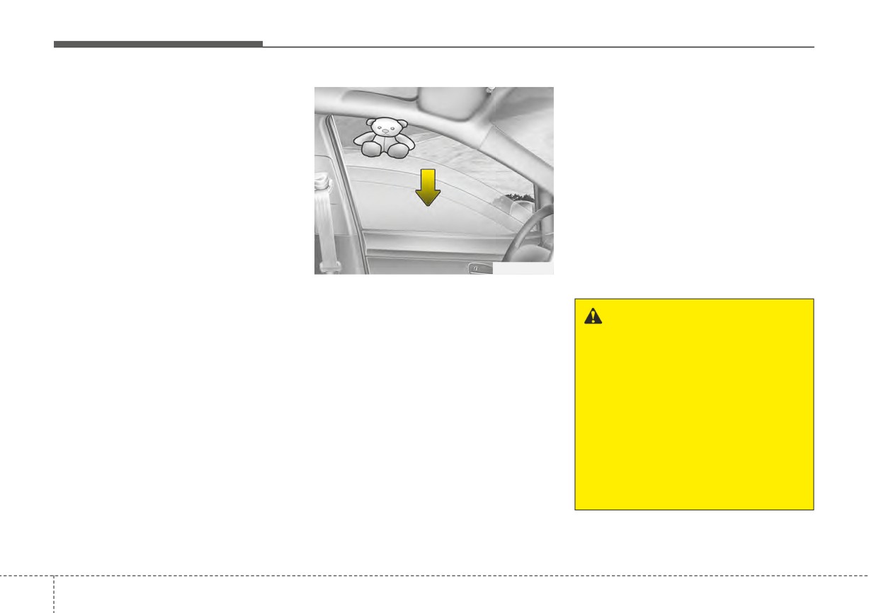
If the power window is not operated
And if the power window switch is
correctly, the automatic power win-
pulled up continuously again within 5
dow system must be reset as follows:
seconds after the window is lowered
by the automatic window reversal
1. Place the ignition switch or
feature, the automatic window rever-
ENGINE START/STOP button to
sal will not operate.
the ON position.
2. Close the window and continue
The automatic reverse feature for the
driver’s window is only active when
pulling up on the driver’s power
window switch for at least 1 sec-
the “auto up” feature is used by fully
pulling up the switch. The automatic
ond after the window is complete-
ly closed.
reverse feature will not operate if the
OUN026013
window is raised using the halfway
position on the power window switch.
Automatic reversal (if equipped)
If the upward movement of the win-
dow is blocked by an object or part of
WARNING
the body, the window will detect the
Always check for obstructions
resistance and will stop upward
before raising any window to
movement. The window will then
avoid injuries or vehicle dam-
lower approximately 11.8 in. (30 cm)
age. If an object less than 0.16
to allow the object to be cleared.
in. (4 mm) in diameter is caught
between the window glass and
If the window detects the resistance
while the power window switch is
the upper window channel, the
automatic reverse window may
pulled up continuously, the window
will stop upward movement then
not detect the resistance and
will not stop and reverse direc-
lower approximately 1 in. (2.5 cm).
tion.
4
36
Features of your vehicle
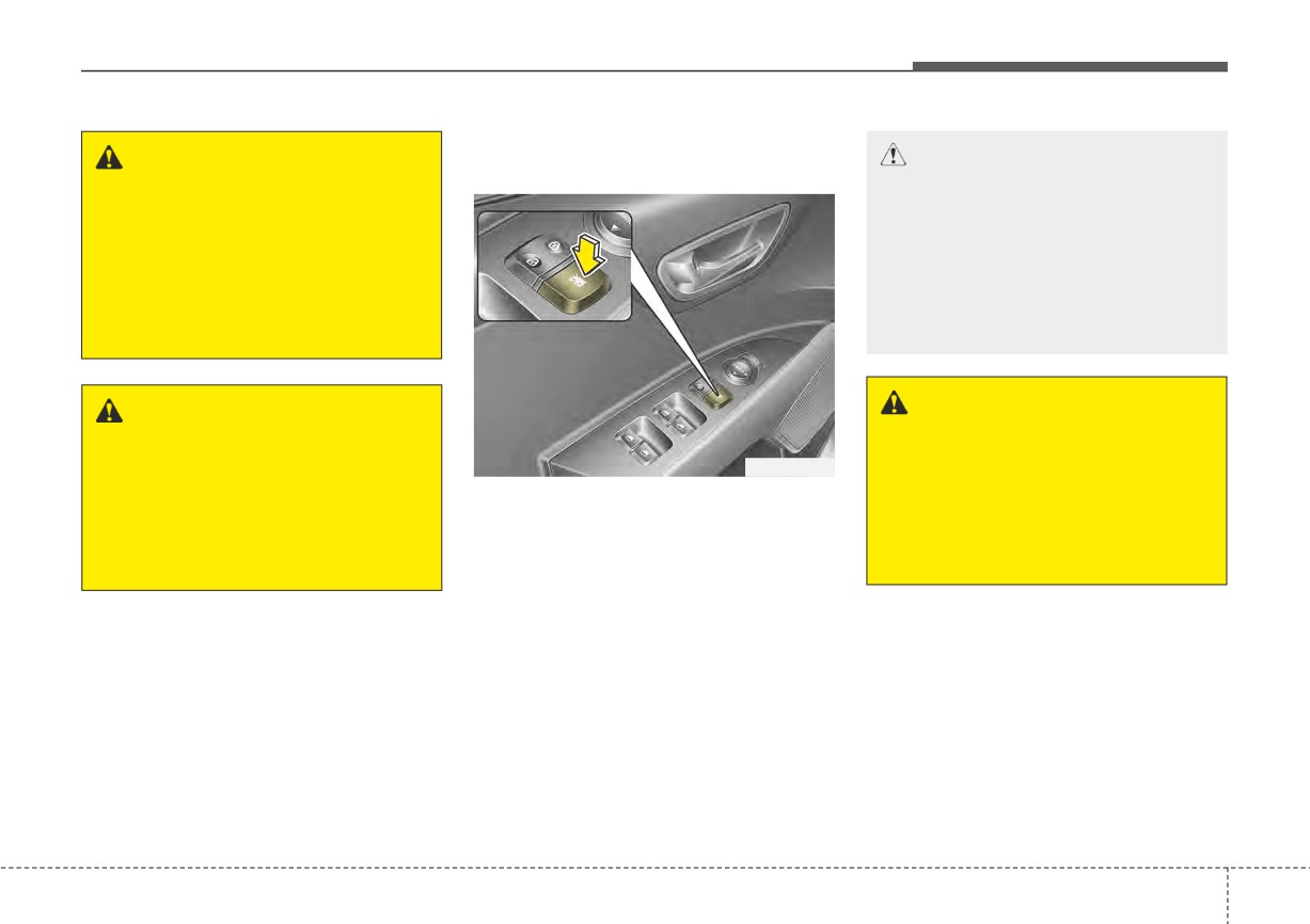
Power window lock button
WARNING
(if equipped)
CAUTION
- Opening/Closing Window
The automatic reverse feature
doesn’t activate while resetting
To prevent possible damage to
the power window system. Make
the power window system, do
sure body parts or other objects
not open or close two windows
are safely out of the way before
or more at the same time. This
closing the windows to avoid
will also ensure the longevity of
injuries or vehicle damage.
the fuse.
WARNING - Power win-
WARNING
dows
Do not install any accessories
in the vehicle that extend into
OSC040017
Do not allow children to play
with the power windows. Keep
the open window area. Such
The driver can disable the power win-
the power window lock button
objects could prevent the auto-
dow switches on the rear passengers'
(on the driver's door) in the
matic reverse feature from func-
doors by pressing the power window
LOCK (pressed) position.
tioning.
lock switch to the lock position
(pressed).
When the power window lock
switch is pressed:
• The driver's master control can
operate all the power windows.
• The front passenger's control
can operate the front passen-
ger's power window.
• The rear passenger's control
cannot operate the rear passen-
ger's power window.
4
37
Features of your vehicle
Always double check to make sure
all arms, hands, head and other
obstructions are safely out of the way
before closing a window.
4
38
Features of your vehicle
HOOD
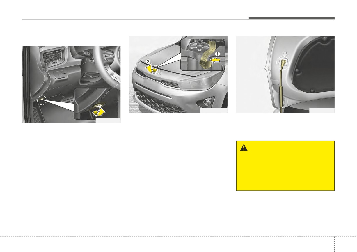
Opening the hood
OSC041504N
OYB046024
2. Go to the front of the vehicle, raise
3. Pull out the support rod.
OYB046022
the hood slightly, push the second-
4. Hold the hood open with the sup-
1. Pull the release lever to unlatch
ary latch
(1) inside of the hood
port rod.
the hood. The hood should pop
center and lift the hood (2).
open slightly.
WARNING - Hot parts
Open the hood after turning off the
engine on a flat surface, shifting the
Grasp the support rod in the
shift lever to the P (Park) position for
area wrapped in rubber. The
Intelligent Variable Transmission and
rubber will help prevent you
setting the parking brake.
from being burned by hot metal
when the engine is hot.
4
39
Features of your vehicle
Closing the hood
Hood open warning
WARNING - Fire risk
(if equipped)
1. Before closing the hood, check the
Do not leave gloves, rags or any
following:
other combustible material in the
• All filler caps in the engine com-
engine compartment. Doing so
partment must be correctly
may cause a heat-induced fire.
installed.
• Gloves, rags or any other com-
bustible material must be
removed from the engine com-
partment.
2. Return the support rod to its clip to
prevent it from rattling.
3. Lower the hood until it is about 12
OST040547L
inches(30 cm) above the closed
position and let it drop. Make sure
The warning message will appear on
that it locks into place.
the LCD display when hood is open.
4. Check that the hood has engaged
The warning chime will operate when
properly. If the hood can be raised
the vehicle is being driven at or
slightly, it is not properly engaged.
above 2 mph (3 km/h) with the hood
open.
Open it again and close it with a lit-
tle more force.
4
40
Features of your vehicle
WARNING - Unsecured
WARNING
engine hood
The support rod must be insert-
Always double check to be sure
ed completely into the hole
that the hood is firmly latched
whenever you inspect the
before driving away. If it is not
engine compartment. This will
latched, the hood could fly open
prevent the hood from falling
while the vehicle is being driven,
and possibly injuring you.
causing a total loss of visibility,
which might result in an accident.
CAUTION - Hood
obstruction
Before closing the hood, ensure
that all obstructions are
removed from the hood open-
ing. Closing the hood with an
obstruction present in the hood
opening may result in vehicle
damage.
4
41
Features of your vehicle
FUEL FILLER DOOR
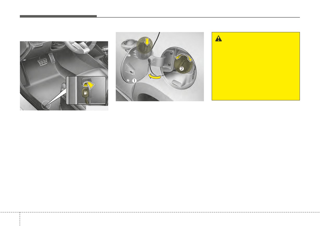
Opening the fuel filler door
WARNING
Before refueling, be sure to
check what type of fuel is used
for your vehicle.
If you put diesel fuel into a
gasoline-powered vehicle or
gasoline into a diesel-powered
vehicle, it may affect the fuel
system and cause serious dam-
age to the vehicle.
OYB046026
1. Stop the engine.
OSC040505
2. To open the fuel filler door, pull the
The fuel filler door must be opened
fuel filler door opener up.
from inside the vehicle by pulling up
3. Pull open the fuel filler door (1) out
the fuel filler door opener.
to fully open.
If the fuel filler door does not open
4. To remove the cap turn the fuel
because ice has formed around it,
filler cap (2) counterclockwise.
tap lightly or push on the lid to break
the ice and release the lid. Do not pry
5. Refuel as needed.
on the lid. If necessary, spray around
the lid with an approved de-icer fluid
(do not use radiator anti-freeze) or
move the vehicle to a warm place
and allow the ice to melt.
4
42
Features of your vehicle
Closing the fuel filler door
✽ NOTICE
WARNING - Static
1. To install the cap, turn it clockwise
When refueling on unlevel ground,
electricity
until it “clicks” one time. This indi-
the fuel gauge may not point to the F
cates that the cap is securely tight-
position.
•
Before touching the fuel noz-
ened.
It is not a malfunction. If you move
zle, you should eliminate
your vehicle to level ground, the fuel
potentially dangerous static
2. Close the fuel filler door and push
gauge will move to the full position.
electricity discharge by touch-
it lightly and make sure that it is
ing another metal part of the
securely closed.
vehicle, a safe distance away
✽ NOTICE
from the fuel filler neck, noz-
WARNING - Refueling
Tighten the cap until it clicks one
zle, or other gas source.
time,otherwise the check engine
Always remove the fuel cap
•
Do not get back into a vehicle
warning indicator light will illumi-
carefully and slowly. If the cap
once you have begun refuel-
nate.
is venting fuel or if you hear a
ing since you can generate
hissing sound, wait until the
static electricity by touching,
Always check that the fuel cap is
condition stops before com-
rubbing or sliding against any
installed securely to prevent fuel
pletely removing the cap.
item or fabric (polyester, satin,
spillage in the event of an accident.
If pressurized fuel sprays out, it
nylon, etc.) capable of produc-
can cover your clothes or skin
ing static electricity. Static
and subject you to the risk of
WARNING - Fire/
electricity discharge can
fire and burns.
explosion risk
ignite fuel vapors resulting in
rapid burning. If you must re-
Read and follow all warnings
enter the vehicle, you should
posted at the gas station facili-
once again eliminate poten-
ty. Failure to follow all warnings
tially dangerous static elec-
will result in severe personal
tricity discharge by touching a
injury, severe burns or death
metal part of the vehicle, away
due to fire or explosion.
from the fuel filler neck, noz-
zle or other gasoline source.
4
43
Features of your vehicle
Make sure to refuel your vehicle
WARNING - Portable fuel
WARNING - Refueling &
according to the “Fuel requirements”
container
Vehicle fires
suggested in chapter 1.
When using an approved portable
When refueling, always shut the
If the fuel filler cap requires replace-
fuel container, be sure to place
engine off. Sparks produced by
ment, use only a genuine Kia cap or
the container on the ground prior
electrical components related
the equivalent specified for your vehi-
to refueling. Static electricity dis-
to the engine can ignite fuel
cle. An incorrect fuel filler cap can
charge from the container can
vapors, causing a fire. Once
result in a serious malfunction of the
ignite fuel vapors causing a fire.
refueling is complete, check to
fuel system or emission control sys-
Once refueling has begun, con-
make sure the filler cap and
tem.
tact with the vehicle should be
filler door are securely closed,
maintained until the filling is com-
before starting the engine.
CAUTION - Exterior paint
plete. Use only approved portable
Do not spill fuel on the exterior
plastic fuel containers designed
surfaces of the vehicle. Any
to carry and store gasoline.
WARNING - Smoking
type of fuel spilled on painted
DO NOT use matches or a lighter
surfaces may damage the paint.
and DO NOT SMOKE or leave a
WARNING
- Cell phone
lit cigarette in your vehicle while
fires
at a gas station especially during
Do not use cellular phones while
refueling. Automotive fuel is
refueling. Electric current and/or
highly flammable and can, when
electronic interference from cel-
ignited, result in fire.
lular phones can potentially
ignite fuel vapors causing a fire.
4
44
Features of your vehicle
STEERING WHEEL
Electric power steering (EPS)
✽ NOTICE
(Continued)
•
When abnormality is detected in
Power steering uses a motor to
The following symptoms may occur
the electric power steering system,
assist you in steering the vehicle. If
during normal vehicle operation:
to prevent a deadly accident, the
the engine is off or if the power steer-
•
The EPS warning light does not
steering assist function will stop.
ing system becomes inoperative, the
illuminate.
At this time, the warning light
vehicle may still be steered, but it will
•
The steering effort is increased
turns on or blinks on the cluster.
require increased steering effort.
immediately after turning the igni-
The steering wheel may become
tion
switch
or
ENGINE
The electric power steering is con-
difficult to control or operate.
START/STOP button to the ON
trolled by the power steering control
Have your vehicle checked imme-
position. This happens as the sys-
unit which senses the steering wheel
diately, after moving the vehicle to
tem performs the EPS system
torque and vehicle speed to com-
a safe zone.
diagnostics. When the diagnostics
mand the motor.
•
The steering effort increases if the
are completed, the steering wheel
The steering wheel becomes heavier
steering wheel is rotated continu-
will return to its normal condition
as the vehicle’s speed increases and
ously when the vehicle is not in
•
A click noise may be heard from
becomes lighter as the vehicle’s
motion. However, after a few min-
the EPS relay after the ignition
speed decreases for better control of
utes, it will return to its normal
switch is turned to the ON or
the steering wheel.
condition.
LOCK position or ENGINE
•
When you operate the steering
Should you notice any change in the
START/STOP button to the ON or
wheel in low temperature, noise
effort required to steer during normal
OFF position.
may occur. If the temperature
vehicle operation, have the power
•
Motor noise may be heard when
rises, the noise will likely disap-
steering checked by an authorized
the vehicle is at a stop or at a low
pear. This is a normal condition.
Kia dealer.
driving speed.
•
When the charging system warn-
(Continued)
ing light comes on or the battery
voltage is low (when the alternator
or battery does not operate nor-
mally), the steering wheel may get
heavy and become difficult to con-
trol or operate abnormally.
4
45
Features of your vehicle
If the Electric Power Steering System
Tilt steering (if equipped)
does not operate normally, the warn-
Tilt steering allows you to adjust the
ing light will illuminate on the instru-
steering wheel before you drive. You
ment cluster. The steering wheel may
can also raise it to give your legs
require increased steering effort.
more room when you exit and enter
Take your vehicle to an authorized
the vehicle.
Kia dealer and have the vehicle
checked as soon as possible.
The steering wheel should be posi-
tioned so that it is comfortable for
you to drive, while permitting you to
see the instrument panel warning
OSC041027N
lights and gauges.
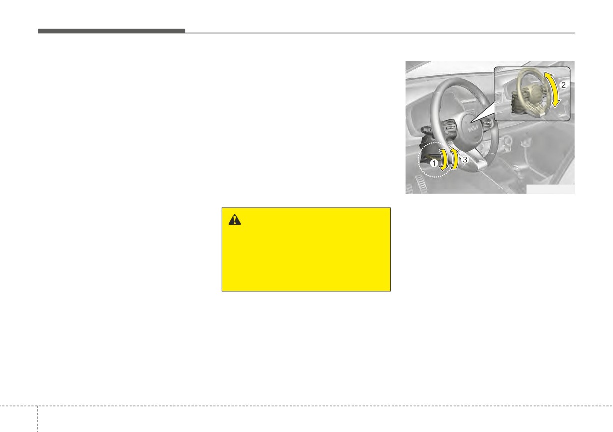
To change the steering wheel angle,
pull down the lock release lever (1),
WARNING
- Steering
adjust the steering wheel to the
wheel adjustment
desired angle (2), then pull up the
Never adjust the angle and
lock-release lever to lock
(3) the
height of the steering wheel
steering wheel in place. Be sure to
while driving. You may lose
adjust the steering wheel to the
steering control
desired position before driving.
✽ NOTICE
After adjustment, sometimes the
lock release lever may not lock the
steering wheel. It is not a malfunc-
tion. This occurs when two gears are
not engaged correctly. In this case,
adjust the steering wheel again and
then lock the steering wheel.
4
46
Features of your vehicle
Horn
OSC041046N
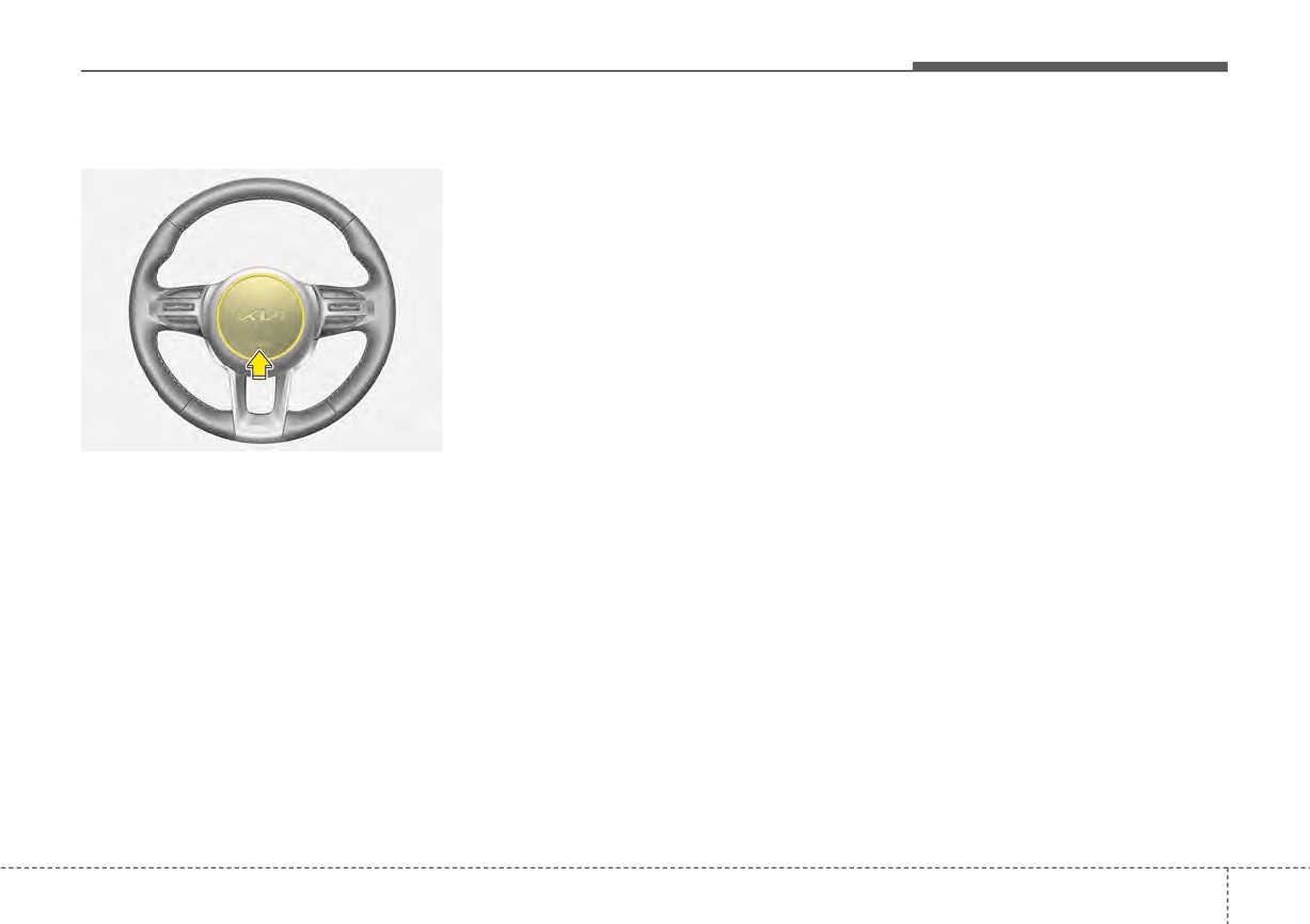
To sound the horn, press the horn
symbols on your steering wheel.
Check the horn regularly to be sure it
operates properly.
✽ NOTICE
To sound the horn, press the area
indicated by the horn symbol on
your steering wheel
(see illustra-
tion). The horn will operate only
when this area is pressed.
4
47
Features of your vehicle
MIRRORS
Inside rearview mirror
Day/night rearview mirror
Day/night rearview mirror with
Telematics function (if equipped)
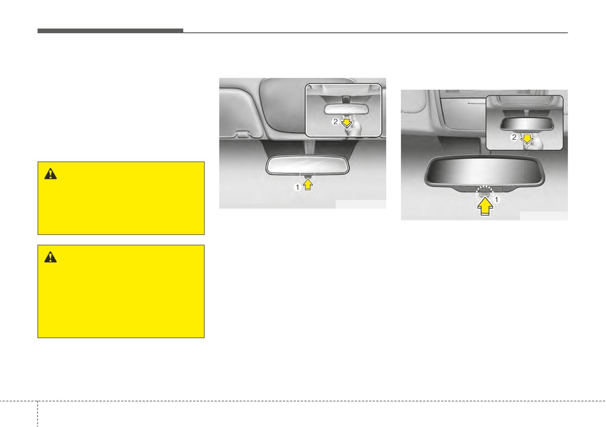
Adjust the rearview mirror so that the
center view through the rear window
is seen. Make this adjustment before
you start driving.
Do not place objects in the rear seat
which would interfere with your vision
through the rear window.
WARNING - Mirror
adjustment
Do not adjust the rearview mirror
OUM046434L
while the vehicle is moving. This
OBDM049458
Make this adjustment before you
could result in loss of control.
start driving and while the day/night
For day and night function:
lever is in the day position (1).
Make this adjustment before you
Pull the day/night lever toward you
start driving and while the day/night
WARNING
(2) to reduce the glare from the
lever (1) is in the day position.
Do not modify the inside mirror
headlights of the vehicles behind you
Pull the day/night lever
(2) toward
in any manner including
during night driving.
you to reduce the glare from the
installing a wider mirror. Doing
Remember that you lose some
headlights of the vehicles behind you
so could result in injury during
rearview clarity in the night position.
during night driving.
an accident or deployment of
the air bag.
Remember that you lose some
❈ (1) : Day, (2) : Night
rearview clarity in the night position.
❈ (1) : Day, (2) : Night
4
48
Features of your vehicle
Outside rearview mirror
CAUTION - Rearview
Be sure to adjust mirror angles
mirror
before driving.
Do not scrape ice off the mirror
Your vehicle is equipped with both
face; this may damage the sur-
left-hand and right-hand outside
face of the glass. If ice should
rearview mirrors. The mirrors can be
restrict movement of the mirror,
adjusted remotely with the remote
do not force the mirror for
switch
(if equipped). The mirror
adjustment. To remove ice, use
heads can be folded to prevent dam-
a deicer spray, or a sponge or
age during an automatic car wash or
soft cloth with very warm water.
when passing through a narrow
OSC040588N
street.
For Telematics button function:
The right outside rearview mirror is
WARNING - Mirror
1. Virtual Assistant button
convex. Objects seen in the mirror
adjustment
2. UVO button
are closer than they appear.
Do not adjust or fold the outside
3. Roadside Assist button
Use your interior rearview mirror or
rearview mirrors while the vehi-
direct observation to determine the
cle is moving. This could result
actual distance of following vehicles
in loss of control.
Telematics buttons are also located
when changing lanes.
on the mirror.
CAUTION
When cleaning the mirror, use a
paper towel or similar material
dampened with glass cleaner.
Do not spray glass cleaner
directly on the mirror. It may
cause the liquid cleaner to enter
the mirror housing.
4
49
Features of your vehicle
Remote control
After adjustment, press the R or L Folding the outside rearview mirror
button again to prevent any inadver-
tent adjustment.
CAUTION - Outside mirror
•
The mirrors stop moving when
they reach the maximum
adjusting angles, but the
motor continues to operate
while the switch is pressed.
Do not press the switch longer
than necessary as the motor
OSC040518
may be damaged.
OYB046034
Electric type
•
Do not attempt to adjust the
Manual type
outside rearview mirror by
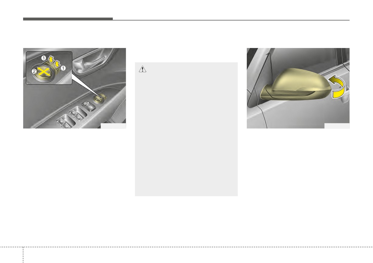
The electric remote control mirror
To fold the outside review mirror,
hand. Doing so may damage
switch allows you to adjust the posi-
grasp the housing of the mirror and
the parts.
tion of the left and right outside
then fold it toward the rear of the
rearview mirrors. To adjust the posi-
•
When the mirror control, press
vehicle.
tion of either mirror, the ignition
exactly “
”(2) marking area.
switch or ENGINE START/STOP but-
Otherwise, the mirror will
ton should be in the ACC or ON posi-
move to unintended direction
tion.
or malfunction.
To adjust the position of either mirror,
press the R or L button (1) to select
the right side mirror or the left side
mirror, then press a corresponding
point (▲) on the mirror adjustment
control to position the selected mirror
up, down, left or right.
4
50
Features of your vehicle
INSTRUMENT CLUSTER
■ Type A
1. Tachometer
2. Speedometer
3. Engine coolant temperature gauge
4. Fuel gauge
5. Warning and indicator lights
■ Type B
6. LCD display
❈ The actual cluster and contents of the
LCD display in the vehicle may differ from
the illustration.
OSC040101/OSC040102
4
51
Features of your vehicle
Instrument Cluster Control
■ Type A
LCD Display Control
Adjusting Instrument Cluster
■ Type A
Illumination
OSC047127N
■ Type B
OSC041048N
■ Type B
OSC041047N
The instrument panel illumination
intensity can be adjusted by pressing
the control switch with the headlight
switch in any position when the igni-
tion
switch
or
ENGINE
OJA040571L
START/STOP button is in the ON
• If you hold the illumination control
OSC041049N
position.
button (“+” or “-”), the brightness
will be changed continuously.
The LCD Display modes can be
changed by using the control buttons
• If the brightness reaches the maxi-
on the steering wheel.
mum or minimum level, an alarm
will sound.
4
52
Features of your vehicle
[Type A]
Gauges
Tachometer
(1) TRIP : TRIP button for changing
Speedometer
trip modes
(2) RESET : RESET button for reset-
ting items
[Type B]
(1)
: MODE button for changing
LCD modes
(2)
/
: MOVE scroll switch to
select items
(3) OK : SET/RESET button for set-
OYB046106
ting or resetting items
OSC040103
The tachometer indicates the
approximate number of engine revo-
The speedometer indicates the for-
❈ For the LCD modes, refer to “LCD
ward speed of the vehicle.
lutions per minute (rpm).
Display” in this chapter.
Use the tachometer to select the cor-
The speedometer is calibrated in
rect shift points and to prevent lug-
miles per hour and/or kilometers per
hour.
ging and/or over-revving the engine.
CAUTION - Red zone
Do not operate the engine with-
in the tachometer's RED ZONE.
This may cause severe engine
damage.
4
53
Features of your vehicle
Engine coolant temperature
Fuel gauge
gauge
WARNING - Hot radiator
Never remove the radiator cap
when the engine is hot. The
engine coolant is under pres-
sure and could cause severe
burns. Wait until the engine is
cool before adding coolant to
the reservoir.
OSC047105N
OSC047104N
The fuel gauge indicates the approx-
imate amount of fuel remaining in the
This gauge shows the temperature
fuel tank.
of the engine coolant when the igni-
tion switch or ENGINE START/STOP
button is ON.
If the gauge pointer moves beyond
the normal range area (between the
C-H) toward the “H” position, it indi-
cates overheating that may damage
the engine.
Do not continue driving with an over-
heated engine. If your vehicle over-
heats, refer to “If the engine over-
heats” in chapter 6.
4
54
Features of your vehicle
✽ NOTICE
✽ NOTICE - Fuel gauge
Odometer
• The fuel tank capacity is given in
Running out of fuel can expose vehi-
■ Type A
chapter 8.
cle occupants to danger. You must
• The fuel gauge is supplemented by
stop and obtain additional fuel as
a distance to empty mileage,
soon as possible after the warning
and/or a low fuel warning light
light comes on or when the gauge
which will illuminate when the
indicator comes close to the
“E”
fuel tank is nearly empty.
(Empty) level.
• On inclines or curves, the fuel
gauge pointer may fluctuate or the
CAUTION - Low fuel
low fuel warning light may come
Avoid driving with an extremely
on earlier than usual due to the
OSC040153
low fuel level. Running out of
movement of fuel in the tank.
■ Type B
fuel could cause the engine to
misfire, damaging the catalytic
converter.
✽ NOTICE
The fuel display may not be accu-
rate if the vehicle is on an incline.
ODL3A040125
The odometer indicates the total dis-
tance the vehicle has been driven.
You will also find the odometer useful
to determine when periodic mainte-
nance should be performed.
4
55
Features of your vehicle
- Odometer range :
Outside Temperature Gauge
- Temperature range :
0 ~ 999,999 miles or 0 ~ 1,599,999
- Type A Cluster : -40°F ~ 199°F
■ Type A
km.
(-40°C ~ 85°C)
- Type B Cluster : - 40°F ~ 211°F
(- 40°C ~ 85°C)
OSC040154
■ Type B
OSC040155
This gauge indicates the current out-
side air temperatures by 1°F (1°C).
4
56
Features of your vehicle
The outside temperature on the dis-
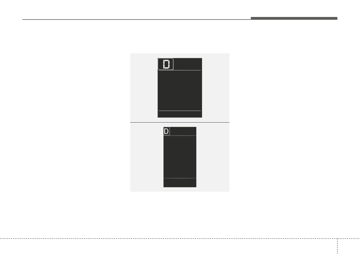
Transmission Shift Indicator
• Park : P
play may not change immediately
• Reverse : R
Intelligent Variable Transmission
like a general thermometer to pre-
■ Type A
• Neutral : N
vent the driver from being inattentive.
• Drive : D
To change the temperature unit (from
°C to °F or from °F to °C)
• Manual Mode : 1, 2, 3, 4, 5, 6, 7, 8
• Type A Cluster
Press the TRIP button for 5 seconds,
the temperature unit is blink. And
then press the RESET button, the
temperature unit is changed. Press
OYB040551L
the TRIP button for more than one
■ Type B
second.
• Type B Cluster
The temperature unit can be
changed by using the “User Settings”
mode of the LCD Display.
❈ For more details, refer to “LCD
Display” in this chapter.
ODL3049128
This indicator displays which intelli-
gent variable transmission shift lever
is selected.
4
57