Volvo 50-42LE transmission. Service manual - part 16
 

  Index      Volvo     Volvo 50-42LE transmission - service and repair manual 2004 year


Search            


Content   ..  14  15  16  17   ..


Volvo 50-42LE transmission. Service manual - part 16


AUTOMATIC TRANSMISSION SERVICE GROUP

Technical Service Information

63

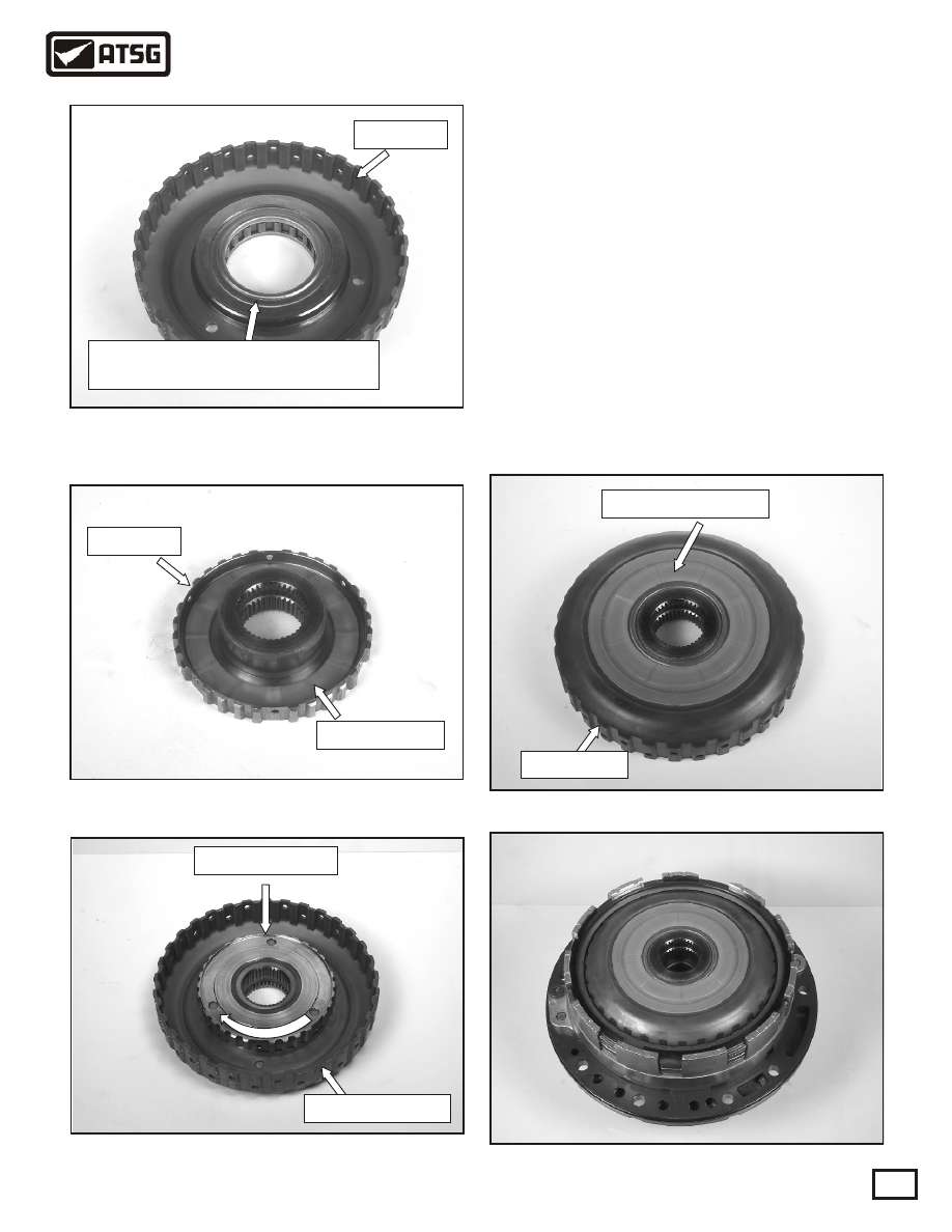
 80. Assemble the sprag, I.D. rib facing down, and   
       end bearings into the outer race, as shown in 
       Figure  133. Use the illustration in Figure 131
       to identify the I.D. rib. 
 81. Assemble the inner thrust washer into the inner 
       sprag race as shown in Figure 134.
 82. Assemble the inner sprag race into the sprag 
       and outer race. The inner race must freewheel
       clockwise and lock counterclockwise when 
       holding the outer race. See Figure 135.
 83. Turn the complete assembly over and assemble
       the rear thrust washer into the outer race shown
       in Figure 136.
 84. Assemble the complete B2 coast brake hub
       assembly into the already completed pump
       assembly and set aside for final assembly into
       the case. See Figure 137.

Figure 136

Figure 137

Figure 135

Copyright © 2004 ATSG

Install the sprag and end bearings

the I.D. rib should face down

Inner race

Figure 133

Figure 134

Thrust washer

Outer race

Turn inner race

Hold outer race

Freewheel

Rear thrust washer

Outer race

SUB-ASSEMBLIES

"B2 COAST BRAKE HUB AND SPRAG Contd."

AUTOMATIC TRANSMISSION SERVICE GROUP

Technical Service Information

64

 85. Remove the snap ring and  the C3 clutch     
       assembly from the C3 drum as shown below  
       in Figure 138.
 86. Remove the snap ring, C3 return spring assy.
       and C3 piston as shown in Figure 139.
 87. Inspect the bushing in the front of the C3 drum
       and replace as necessary. See Figure 140.
 88. Turn the C3 drum over and inspect the rear
       bushing in the drum. Inspect the sprag race as
       shown in Figure 141. Replace as necessary.
 89. Inspect the check ball assembly for debris and
       replace the inner and outer o-rings on the C3
       piston. See Figure 142.

SUB-ASSEMBLIES

"C3 UNDERDRIVE CLUTCH DRUM"

Figure 138

Figure 139

Figure 141

Figure 142

Snap ring

Continued on Page 65

C3 drum

Snap ring

Copyright © 2004 ATSG

Figure 140

Inspect bushing

Inspect bushing

Inspect sprag race

C3 piston

Inner o-ring

Outer o-ring

Check ball

Return spring

C3 piston

AUTOMATIC TRANSMISSION SERVICE GROUP

Technical Service Information

65

 90. Lubricate the inside of the C3 drum in the areas
       shown in Figure 143.
 91. Install the C3 piston into the C3 drum as shown
       in Figure 144.
 92. Install the return spring into the C3 piston and
       install the retaining snap ring as shown in 
       Figure 145.
 93. Install the C3 clutch assembly into the C3 drum
       as shown in Figure 147, using Figure 146 as a
       guide. Install the .020" bottom steel first, then
       install the cushion plate in the direction shown 
       in Figure 146. Install the remaining clutch 
       plates, steel plates, pressure plate and snap ring. 
       Using a feeler gage check clutch clearance  
       between the pressure plate and the top clutch 
       plate. The clearance should be .032" - .038."

Figure 143

Figure 145

Figure 144

Figure 146

Figure 147

Lubricate

C3 piston

Snap ring

Return spring

C3 clutch assembly

SUB-ASSEMBLIES

"C3 UNDERDRIVE CLUTCH DRUM Contd."

Snap ring

Pressure plate
thickness .150"

4 clutch plates

thickness .068"

Bottom steel plate

thickness .020"

4 steel plates

thickness .072"

Cushion plate

Install

.032" to .038"

clearance

.035"

Copyright © 2004 ATSG

AUTOMATIC TRANSMISSION SERVICE GROUP

Technical Service Information

66

 94. Remove the retainer from the top of the outer
       sprag race as shown in Figure 148.
 95. Remove the F3 sprag and end bearings from the
       outer race as shown in Figure 149.
 96. Inspect the end bearings for wear as shown in 
       Figure 150. Replace as necessary.
 97. Inspect the sprag elements for wear as shown
       in Figure 151, and replace as necessary.
 98. Inspect the area where the sprag rides, in the 
       outer race, for wear or scoring. Replace as 
       necessary. See Figure 152.

Figure 148

Figure 150

Figure 152

Continued on Page 67

Figure 151

Figure 149

SUB-ASSEMBLIES

"F3 UNDER DRIVE SPRAG"

Check for wear

Check the sprag elements for wear

F3 sprag assembly

Retainer

F3 sprag and end bearings

Sprag and end bearings

I.D. rib

Check for wear

Outer sprag race

Copyright © 2004 ATSG


Content   ..  14  15  16  17   ..