Volvo 50-42LE transmission. Service manual - part 15
 

  Index      Volvo     Volvo 50-42LE transmission - service and repair manual 2004 year


Search            


Content   ..  13  14  15  16   ..


Volvo 50-42LE transmission. Service manual - part 15


Smaller

diameter bolt

16mm long

AUTOMATIC TRANSMISSION SERVICE GROUP

Technical Service Information

59

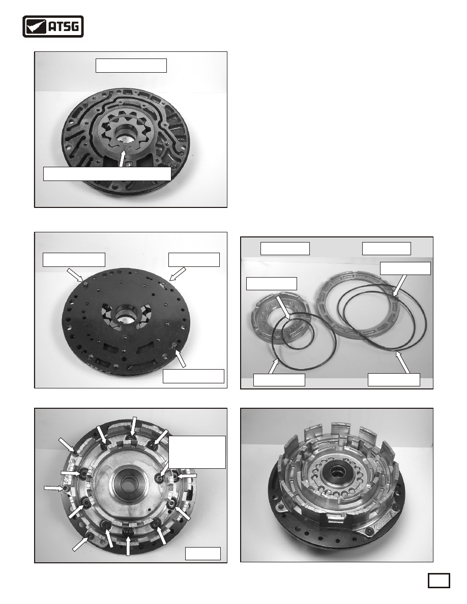
 62. Assemble the pump gears into the pump body
       with the dot on the pump gears facing down,
       as shown in Figure 113. Lubricate the gears 
       with a small amount of ATF.
 62. Assemble the pump plate on over the two
        alignment pins shown in Figure 114.
 63. Assemble the piston housing / stator shaft thru
       the pump body over the alignment pins as 
       shown in Figure 115. Using a 30 torx bit, install
       the thirteen 13mm  long retaining bolts and
       torque to 89-124 in.lb. Torque the 16mm long
       bolt to 53-62 in.lb.
 64. Replace the inner and outer B1 and B2 piston
       o-rings as shown in Figure 116.
 65. Lubricate the piston o-rings and install the 
       pistons into the housing shown in Figure 117.

Pump assembly

Figure 116

Figure 117

Figure 115

Copyright © 2004 ATSG

Dot on pump gears face down

Alignment pin

Alignment pin

B1 piston 

B2 piston 

Inner o-ring

Outer o-ring

Outer o-ring

Inner o-ring

Figure 113

Figure 114

Pump plate

SUB-ASSEMBLIES

"PUMP" CONTINUED

Continued on Page 60

30 torx

AUTOMATIC TRANSMISSION SERVICE GROUP

Technical Service Information

60

 66. Using a suitable press, depress the B1 return
       spring and assemble the retaining snap ring,
       as shown in Figure 118.
 67. Assemble the B2 second coast brake hub thrust
       washer as shown in Figure 119.
 68. Assemble the two B1 steel plates and two B1
       clutch plates into the housing as shown in 
       Figure 121. Refer to the exploded view in 
       Figure 120 for assembly purposes.
 69. Assemble the return spring assembly into the 
       housing as shown in Figure 122.

SUB-ASSEMBLIES

"PUMP" CONTINUED

Figure 118

Figure 119

Figure 121

Figure 122

Thrust washer

Continued on Page 61

Assemble B1 clutch assembly

B1 return spring

Snap ring

B1 clutch assembly

Steel plate

thickness .072"

Pressure plate
thickness .137"

Snap ring

Clutch plate

thickness .070"

Return spring assembly

Copyright © 2004 ATSG

Figure 120

AUTOMATIC TRANSMISSION SERVICE GROUP

Technical Service Information

61

 70. Assemble the B1 upper pressure plate on top of
       the spring retainer as shown in Figure 123.
       Press it down and assemble the retaining snap
       ring. Check B1 clutch clearance using a feeler
       gage. Clearance should be between .030"-.040."
 71. Assemble the B2 clutch assembly into the
       housing starting with the .145" thick pressure
       plate, as shown in Figure 124, ending with the 
       snap ring. Check the clearance between the top
       pressure plate and the top B2 clutch plate. The
       clearance should be between .025"- .030."
 72. Using a rubber tip blow gun, air check the B1
       and B2 clutch assemblies , thru the two ports, 
       as shown in Figure 126.
 73. Install pump o-ring as shown in Figure 127.

Figure 123

Figure 125

Figure 124

Figure 126

Figure 127

SUB-ASSEMBLIES

"PUMP" CONTINUED

B1 upper pressure plate

Caution

spring loaded

.030" to .040"

clearance

.035"

B2 clutch assembly

B2 clutch assembly

Pressure plate
thickness .145"

Snap ring

Clutch plate

thickness .068"

Pressure plate
thickness .145"

Steel plate thickness .100"

.025" to .030"

clearance

.030"

B1 air check

B2 air check

Pump o-ring

AUTOMATIC TRANSMISSION SERVICE GROUP

Technical Service Information

62

 74.  Remove the inner race rotating it clockwise as
        shown in Figure 128.
 75. Turn the inner race upside down to check for
       wear in the area where the sprag rides. Replace
       as necessary. See Figure 129.
 76. Remove the sprag and end bearings from the 
       outer race, as shown in Figure 130, and check
       for wear in the area where the sprag rides.
       Replace as necessary.
 78. Inspect the sprag elements for wear as shown
       in Figure 131. Replace as necessary.
 79. Refer to Figure 132 for a view of the complete
       assembly disassembled.

Figure 128

Figure 130

Figure 132

Continued on Page 63

Figure 131

Figure 129

Check for wear here

Inner race thrust washer

Sprag and end bearings

SUB-ASSEMBLIES

"B2 COAST BRAKE HUB AND SPRAG"

Inner sprag race

Outer race

Sprag elements

I.D. rib

Inner race

thrust washer

Inner race

Sprag and

end bearings

Outer race

Rear thrust

washer


Content   ..  13  14  15  16   ..