Suzuki Grand Vitara JB416 / JB420 / JB419. Service manual - part 557
 

  Index      Suzuki     Suzuki Grand Vitara JB416 / JB420 / JB419 - service and repair manual 2007 year


Search            copyright infringement  


Content   ..  555  556  557  558   ..


Suzuki Grand Vitara JB416 / JB420 / JB419. Service manual - part 557


10E-32 Keyless Start System: 

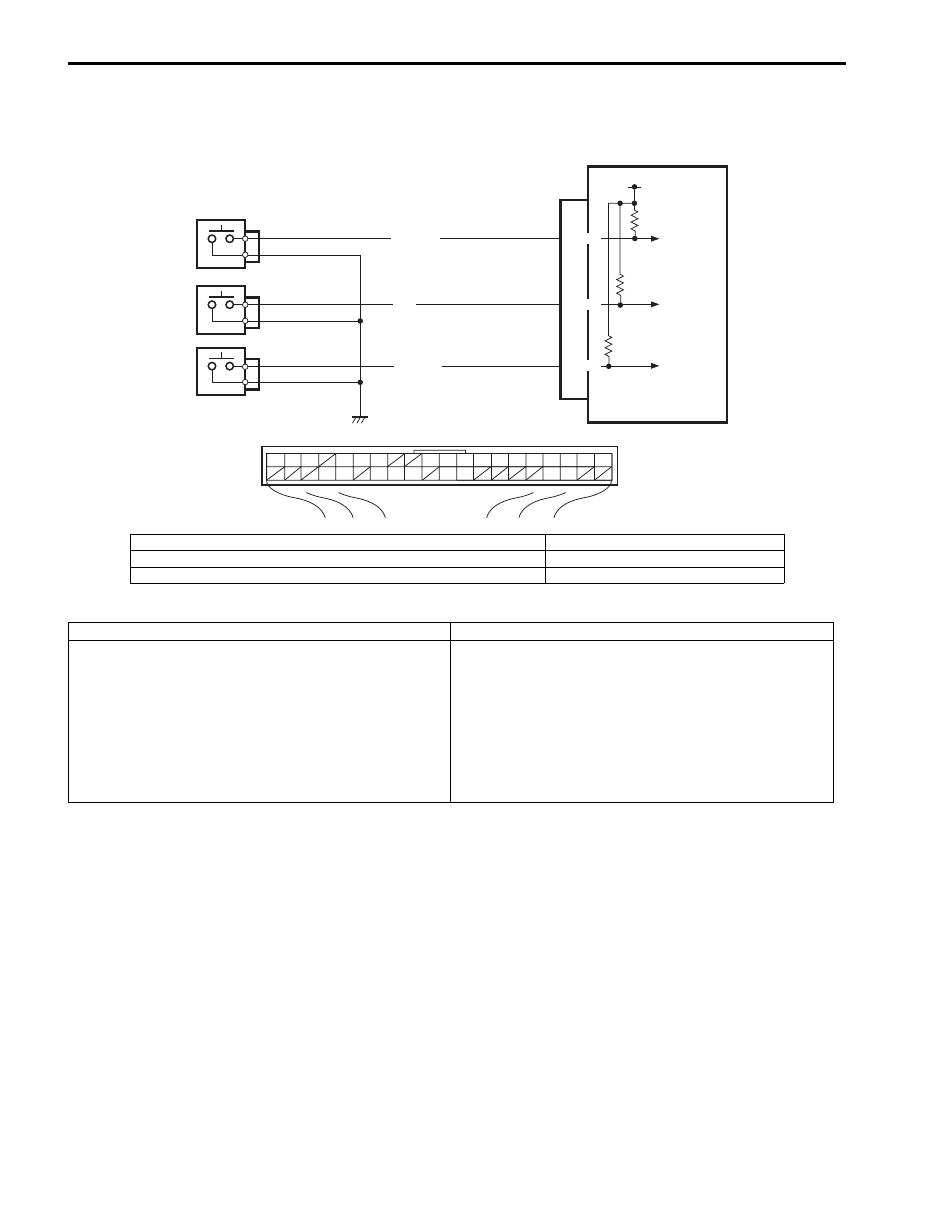
DTC No. 51 / No. 52 / No. 53: Driver Side / Passenger Side / Rear End Door Request Switch Failure

S6JB0AA504022

Wiring Diagram

DTC Detecting Condition and Trouble Area

DTC Confirmation Procedure

1) Clear DTC referring to “DTC Clearance”.
2) Push request switch of each door.
3) Check DTC referring to “DTC Check”.

G44

[A]

1

2

3

4

5

6

7

8

9

10

11

14

15

16
36

34 33 32

30 29

24 23

37

18

19

20

RED/BLK

BLU

YEL/RED

G44-16

G44-36

G44-32

12V

1

2

3

4

I5JB0AA50018-02

[A]: Keyless start control module connector (viewed from harness side)

3. Passenger side door request switch

1. Keyless start control module

4. Rear end door request switch

2. Driver side door request switch

DTC detecting condition

Trouble area

DTC No. 51:
Input signal from driver side door request switch remains 
ON, unchanged for 10 minutes or longer.
DTC No. 52:
Input signal from passenger side door request switch 
remains ON, unchanged for 10 minutes or longer.
DTC No. 53:
Input signal from rear end door request switch remains 
ON, unchanged for 10 minutes or longer.

• Driver side door request switch and its circuit
• Passenger side door request switch and its circuit
• Rear end door request switch and its circuit
• Keyless start control module

Keyless Start System:  10E-33

Troubleshooting

Step

Action

Yes

No

1

Was “Keyless Start System Check” performed?

Go to Step 2.

Go to “Keyless Start 
System Check”
.

2

Request switch check
1) Check related door request switch for function referring 

to “Front Door (Driver and Passenger Side), Rear End 
Door Request Switch Inspection”.

Is each switch in good condition?

Go to Step 3.

Replace request switch.

3

Wire harness check
1) Disconnect connector from keyless start control module.
2) Check for open, short and high resistance in related door 

request switch circuit.

Is each circuit in good condition?

Substitute a known-
good keyless start 
control module and 
recheck.

Repair circuit.

10E-34 Keyless Start System: 

Repair Instructions

Antennas and Request Switches Removal and Installation

S6JB0AA506001

Remove and install antennas and request switches referring to the following figures.

[A]

[B]

[C]

[D]

[E]

[F]

1

1

2

5

6

3

4

I6JB0AA50007-02

[A]: Driver side door antenna and request switch (included in outside door handle assembly)

: Antenna and request switch can not be removed from outside door handle assembly

1. Outside handle assembly

[B]: Passenger side or rear end door antenna and request switch (included in outside door handle assembly)

: Antenna and request switch can not be removed from outside door handle assembly

2. Parking brake lever

[C]: Center antenna

3. Tail end member trim

[D]: Luggage room antenna (5 door model)

4. Rear end door

[E]: Left side luggage room antenna (3 door model)

5. Rear quarter trim (left side)

[F]: Right side luggage room antenna (3 door model)

6. Rear quarter trim (right side)

Keyless Start System:  10E-35

Front Door (Driver and Passenger Side), Rear 
End Door Request Switch Inspection

S6JB0AA506002

1) Remove door trim from door panel.

For front door trim, refer to Step 1) to 3) of “Front 
Door Glass Removal and Installation in Section 9E”.
For rear end door trim, refer to Step 1) of “Rear End 
Door Lock Assembly Removal and Installation in 
Section 9F”.

2) Check for continuity between terminals “1” and “2” at 

each switch position as shown below. If check result 
is not as specified, replace.

Request switch (1) specification
ON position (request switch pushed): Continuity
OFF position (request switch released): No 
continuity

Steering Lock Unit Removal and Installation

S6JB0AA506003

For removal and installation, refer to “Steering Lock 
Assembly (Ignition Switch) Removal and Installation in 
Section 6B”.

Steering Lock Unit Inspection

S6JB0AA506004

Check key reminder switch and ignition knob switch in 
steering lock unit for operation referring to “Ignition 
Switch Inspection in Section 9C”.

Front Door Lock Switch Inspection

S6JB0AA506005

1) Remove door trim from door panel referring to Step 

1) to 3) of “Front Door Glass Removal and 
Installation in Section 9E”.

2) Check for continuity between terminals “1” and “2” at 

each switch position as shown below. If check result 
is not as specified, replace.

Door lock switch specification
LOCK position: No continuity
UNLOCK position: Continuity

2. Outside handle

1

“2”

“1”

2

I5JB0AA50020-01

[A]: Lock
[B]: Unlock

“1”

“2”

[B]

[A]

I5JB0AA50021-02


Content   ..  555  556  557  558   ..