Suzuki Grand Vitara JB416 / JB420 / JB419. Service manual - part 555
 

  Index      Suzuki     Suzuki Grand Vitara JB416 / JB420 / JB419 - service and repair manual 2007 year


Search            copyright infringement  


Content   ..  553  554  555  556   ..


Suzuki Grand Vitara JB416 / JB420 / JB419. Service manual - part 555


10E-24 Keyless Start System: 

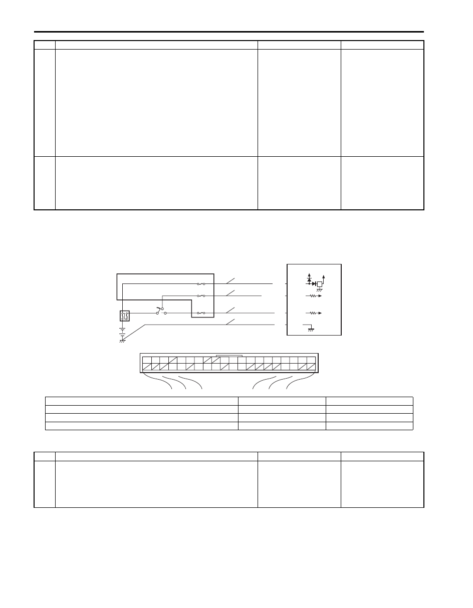
Keyless Start Control Module Power and Ground Circuit Check

S6JB0AA504016

Wiring Diagram

Troubleshooting

4

Wire harness check
1) Turn ignition switch to OFF position.
2) Disconnect connector from keyless start control module, 

steering lock unit and combination meter.

3) Check for open, short and high resistance in following 

circuits.
• Ignition knob switch signal circuit
• Keyless start control module and combination meter 

CAN communication circuit

Is it in good condition?

Go to Step 5.

Repair circuit.

5

Keyless start system operation check
1) With remote controller of which ID code is registered in 

keyless start control module carried with you, try to turn 
ignition knob switch.

Can it be turned to any position other than “LOCK” position?

Replace combination 
meter.

Substitute a known-
good keyless start 
control module and 
recheck.

Step

Action

Yes

No

BLK G44-9

G44-15

G44-10

G44-11

WHT/BLK

WHT

YEL

5V

12V

G44

[A]

1

2

3

4

5

6

7

8

9

10

11

14

15

16
36

34 33 32

30 29

24 23

37

18

19

20

5

2

4

1

3

3

3

6

7

8

9

I7JB01A50003-01

[A]: Keyless start control module connector (viewed from harness side)

4. Main fuse

8. IG ON signal circuit

1. Keyless start control module

5. Junction block

9. Ground circuit

2. Ignition switch

6. Power source circuit

3. Circuit fuse

7. ACC signal circuit

Step

Action

Yes

No

1

Fuse check
1) Turn ignition switch to OFF position.
2) Check circuit fuse and main fuse for condition.

Are fuses in good condition?

Go to Step 2.

Replace fuse(s) and 
check for short.

Keyless Start System:  10E-25

DTC No. 11: Communication Error with Steering Lock Unit

S6JB0AA504017

Wiring Diagram

2

Power supply circuit check
1) Disconnect connector from keyless start control module.
2) Check for proper connection to “Power source”, “ACC 

signal” and “IG ON signal” terminal of keyless start 
control module connector.

3) If OK, measure voltage between following terminals.

• “Power source” terminal of keyless start control 

module connector and vehicle body ground with 
ignition switch is at OFF position

• “ACC signal” terminal of keyless start control module 

connector and vehicle body ground with ignition 
switch is at ACC position

• “IG ON signal” terminal of keyless start control module 

connector and vehicle body ground with ignition 
switch is at ON position

Is each terminal voltage is 10 – 14 V?

Go to Step 3.

Repair defective power 
supply circuit.

3

Ground circuit check
1) Check for proper connection to “Ground” terminal of 

keyless start control module connector.

2) If OK, measure resistance between “Ground” terminal of 

keyless start control module connector and vehicle body 
ground.

Is resistance 1 

 or less?

Power and ground 
circuit is in good 
condition.

Repair ground circuit.

Step

Action

Yes

No

G44

[A]

1

2

3

4

5

6

7

8

9

10

11

14

15

16
36

34 33 32

30 29

24 23

37

18

19

20

5V

G44-20

G44-29

G44-30

G22-3

G22-7

G22-8

5V

5V

ORN

BRN/YEL

BLK/YEL

5V

2

1

3

4

5

I7JB01A50004-01

[A]: Keyless start control module connector (viewed from harness side)

3. Steering lock unit power supply circuit

1. Keyless start control module

4. Steering lock unit signal circuit

2. Steering lock unit

5. Steering lock unit ground circuit

10E-26 Keyless Start System: 

DTC Detecting Condition and Trouble Area

DTC Confirmation Procedure

1) Clear DTC referring to “DTC Clearance”.
2) Turn ignition knob switch pushing ignition knob switch.
3) Check DTC referring to “DTC Check”.

Troubleshooting

DTC detecting condition

Trouble area

No communication is available between keyless start 
control module and steering lock unit.

• Steering lock unit and its circuit
• Keyless start control module

Step

Action

Yes

No

1

Was “Keyless Start System Check” performed?

Go to Step 2.

Go to “Keyless Start 
System Check”.

2

Steering lock unit circuit check
1) Disconnect connector from keyless start control module.
2) Check for proper connection to “Steering lock unit power 

supply”, “Steering lock unit signal” and “Steering lock unit 
ground” terminals of keyless start control module 
connector.

3) If OK, check for open, short and high resistance in 

following circuits.
• Steering lock unit power supply circuit
• Steering lock unit signal circuit
• Steering lock unit ground circuit

Is each circuit in good condition?

Go to Step 3.

Repair circuit.

3

Steering lock unit power supply voltage check
1) Connect connector to keyless start control module.
2) Measure voltage between “Steering lock unit power 

supply” terminal of steering lock unit connector and 
vehicle body ground.

Is voltage 4 – 6 V?

Replace steering lock 
unit.

Substitute a known-
good keyless start 
control module and 
recheck.

Keyless Start System:  10E-27

DTC No. 13 / No. 14: Release Signal Error from Steering Lock Unit / Steering Lock Unit Malfunction

S6JB0AA504018

DTC Detecting Condition and Trouble Area

DTC Confirmation Procedure

1) Clear DTC referring to “DTC Clearance”.
2) Turn ignition knob switch pushing ignition knob switch.
3) Check DTC referring to “DTC Check”.

Troubleshooting
Replace steering lock unit and recheck.

NOTE
Be sure to register the following code when a used keyless start control module is installed. Otherwise 
DTC No.13 is detected by keyless start control module though steering lock unit is normal.
• For petrol engine model with immobilizer control system, ignition key transponder code is not 

registered in ECM.

• For petrol engine model without immobilizer control system, steering lock unit ID code is not 

registered in keyless start control module.

• For diesel engine model, keyless start control module ID code is not registered in ECM.


DTC No. 21 / No. 22: Internal Error of Keyless Start Control Module (EEPROM Reading Error) / 
(EEPROM Writing Error)

S6JB0AA504019

DTC Detecting Condition and Trouble Area

DTC Confirmation Procedure

1) Clear DTC referring to “DTC Clearance”.
2) Turn ignition knob switch pushing ignition knob switch.
3) Push request switch of each door.
4) Check DTC referring to “DTC Check”.

Troubleshooting
Substitute a known-good keyless start control module and recheck.

DTC detecting condition

Trouble area

DTC No. 13:
Although lock release signal is output to steering lock unit, no lock 
release signal is inputted from steering lock unit.
(wire harness is normal)
DTC No. 14:
Although lock release signal is output to steering lock unit, 
steering lock is not released due to temperature rise of steering 
lock unit solenoid and no lock release signal is inputted.
(wire harness is normal)

• Steering lock unit

DTC detecting condition

Trouble area

DTC No. 21:
Data cannot be read from memory in keyless start control module.
DTC No. 22:
Data cannot be written into memory in keyless start control 
module.

• Keyless start control module


Content   ..  553  554  555  556   ..