Suzuki Grand Vitara JB416 / JB420 / JB419. Service manual - part 553
 

  Index      Suzuki     Suzuki Grand Vitara JB416 / JB420 / JB419 - service and repair manual 2007 year


Search            copyright infringement  


Content   ..  551  552  553  554   ..


Suzuki Grand Vitara JB416 / JB420 / JB419. Service manual - part 553


10E-16 Keyless Start System: 

Inspection of Keyless Start Control Module and Its Circuits

S6JB0AA504013

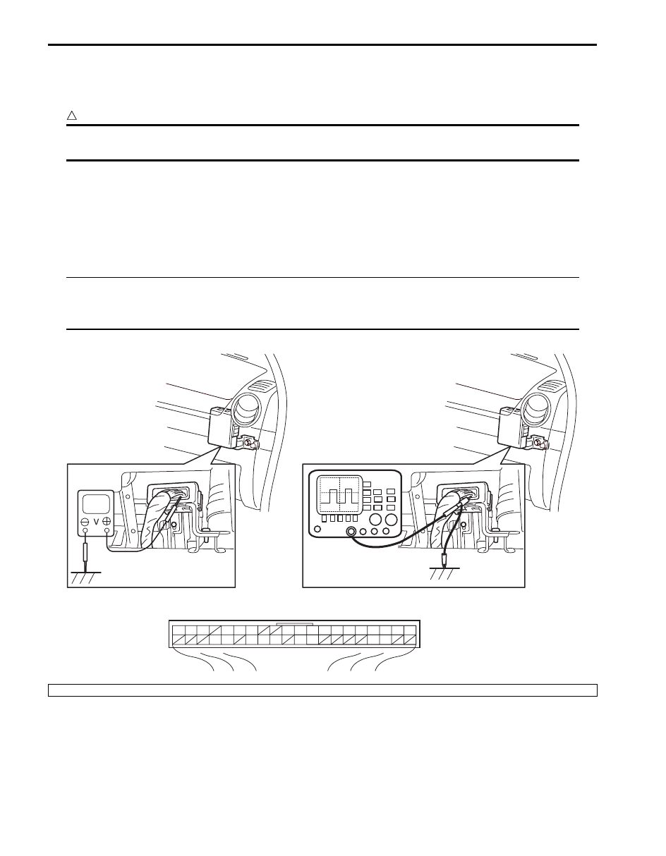
Keyless start control module and its circuits can be checked at keyless start control module wiring couplers by 
measuring voltage and resistance.

CAUTION

!


Keyless start control module cannot be checked by itself. It is strictly prohibited to connect voltmeter 
or ohmmeter to keyless start control module with coupler disconnected from it.


Voltage Check

1) Disconnect negative cable (–) at battery.
2) Remove keyless start control module from vehicle body referring to “Keyless Start Control Module Removal and 

Installation”.

3) Connect connector to keyless start control module.
4) Check voltage at each terminal number of couplers connected.

NOTE

• As each terminal voltage is affected by the battery voltage, confirm that it is 11 V or more when 

ignition switch is ON.

• Voltage with asterisk (*) cannot be measured by voltmeter because it is pulse signal.


G44

[A]

1

2

3

4

5

6

7

8

9

10

11

14

15

16
36

34 33 32

30 29

24 23

37

18

19

20

I5JB0AA50012-02

[A]: Keyless start control module connector (viewed from harness side)

Keyless Start System:  10E-17

Terminal 

Number

Circuit

Normal 

Voltage

Condition

G44-1

Driver side door antenna (–)

*0 – 5 V

Refer to “Reference waveform No. 1: ”

G44-2

Driver side door antenna (+)

G44-3

Rear end door antenna (–)

*0 – 5 V

Refer to “Reference waveform No. 1: ”

G44-4

Rear end door antenna (+)

G44-5

Center antenna (–)

*–1 – 1 V

Refer to “Reference waveform No. 2: ”

G44-6

Center antenna (+)

*–10 – 20 V

G44-7

Luggage room antenna (–)

*–10 – 10 V

Refer to “Reference waveform No. 3: ”

G44-8

Luggage room antenna (+)

*–8 – 14 V

G44-9

Ground for keyless start control module

0 – 1 V

Ignition switch is at all positions

G44-10

Power source

10 – 12 V

Ignition switch is at all positions

G44-11

Ignition switch (ACC signal)

10 – 12 V

Ignition switch is at ACC or ON position

0 – 1 V

Ignition switch is at any position other than 
ACC or ON position

G44-12

G44-13

G44-14

Ignition switch (key reminder signal)

10 – 12 V

Insert ignition key to ignition key cylinder

0 – 1 V

Pull out ignition key from ignition key 
cylinder

G44-15

Ignition switch (ON signal)

10 – 12 V

Ignition switch is at ON position

0 – 1 V

Ignition switch is at any position other than 
ON position

G44-16

Driver side door request switch

10 – 12 V

Request switch of driver side door is 
released

0 – 1 V

Request switch of driver side door is 
pushed

G44-17

G44-18

CAN communication line (low)

*1.6 – 2.5 V

Refer to “Reference waveform No. 4: ”

G44-19

CAN communication line (high)

*2.5 – 3.6 V

G44-20

Power supply for steering lock unit

4 – 6 V

Full time

G44-21

G44-22

G44-23

Passenger side door antenna (–)

*0 – 5 V

Refer to “Reference waveform No. 1: ”

G44-24

Passenger side door antenna (+)

G44-25

G44-26

G44-27

G44-28

G44-29

Signal for steering lock unit

4 – 6 V

Ignition knob switch is at any position other 
than ON and OFF position

*0 – 5 V

Refer to “Reference waveform No. 5: ”

G44-30

Ground for steering lock unit

0 – 1 V

Full time

G44-31

G44-32

Rear end door request switch

10 – 12 V

Request switch of rear end door is at any 
position other than ON position

0 – 1 V

Request switch of rear end door is at ON 
position

G44-33

Driver side door lock switch

*0 – 5 V

Refer to “Reference waveform No. 6: ”

G44-34

Ignition knob switch

10 – 12 V

When pushing ignition knob switch of 
steering lock unit

0 – 1 V

When releasing ignition knob switch of 
steering lock unit

G44-35

G44-36

Passenger side door request switch

10 – 12 V

Request switch of passenger side door is 
at any position other than ON position

0 – 1 V

Request switch of passenger side door is 
at ON position

G44-37

Passenger side door lock switch

*0 – 5 V

Refer to “Reference waveform No. 6: ”

G44-38

10E-18 Keyless Start System: 

Reference waveform No. 1
Driver, passenger and rear end door antenna request 
signals (Request signal (1) transmitted by each door 
antenna when each door request switch is pushed)

Reference waveform No. 2
Center antenna signal
(Request signal (1) transmitted by center antenna when 
each door request switch is pushed)

G44-39

G44-40

Terminal 

Number

Circuit

Normal 

Voltage

Condition

Measurement 
terminal

Driver side door antenna
• CH1: “G44-2” to “G44-9”
• CH2: “G44-1” to “G44-9”
Passenger side door antenna
• CH1: “G44-24” to “G44-9”
• CH2: “G44-23” to “G44-9”
Rear end door antenna
• CH1: “G44-4” to “G44-9”
• CH2: “G44-3” to “G44-9”

Oscilloscope setting CH1: 5 V/DIV, CH2: 5 V/DIV

TIME: 40 ms/DIV

Measurement 
condition

Request switch of each door is 
pushed with remote controller 
carried

I4RS0BA50015-02

Measurement 
terminal

CH1: “G44-6” to “G44-9”
CH2: “G44-5” to “G44-9”

Oscilloscope setting CH1: 10 V/DIV, CH2: 2 V/DIV

TIME: 20 ms/DIV

Measurement 
condition

• Ignition knob switch of steering 

lock unit is pushed

• Request switch of each door is 

pushed with remote controller 
carried

I5JB0AA50024-03

Keyless Start System:  10E-19

Reference waveform No. 3
Luggage room antenna signal
(Request signal (1) transmitted by luggage room 
antenna when each door request switch is pushed)

Reference waveform No. 4
CAN communication signals

Reference waveform No. 5
Steering lock unit signal
(Signal (1) communicated between keyless start control 
module and steering lock unit when measurement 
condition described below applies)

Measurement 
terminal

CH1: “G44-8” to “G44-9”
CH2: “G44-7” to “G44-9”

Oscilloscope setting CH1: 10 V/DIV, CH2: 10 V/DIV

TIME: 20 ms/DIV

Measurement 
condition

Request switch of each door is 
pushed with remote controller 
carried

Measurement 
terminal

CH1: “G44-19” to “G44-9”
CH2: “G44-18” to “G44-9”

Oscilloscope setting CH1: 1 V/DIV, CH2: 1 V/DIV

TIME: 40 

µs/DIV

Measurement 
condition

Ignition switch is at ON position

1. CAN communication line signal (high)
2. CAN communication line signal (low)

I5JB0AA50025-02

I4RS0BA50018-02

Measurement 
terminal

CH1: “G44-29” to “G44-9”

Oscilloscope setting CH1: 2 V/DIV

TIME: 10 ms/DIV

Measurement 
condition

• Ignition knob switch of steering 

lock unit is pushed

• Request switch of each door is 

pushed with remote controller 
carried

I5JB0AA50026-02


Content   ..  551  552  553  554   ..