Suzuki Grand Vitara JB416 / JB420 / JB419. Service manual - part 510
 

  Index      Suzuki     Suzuki Grand Vitara JB416 / JB420 / JB419 - service and repair manual 2007 year


Search            copyright infringement  


Content   ..  508  509  510  511   ..


Suzuki Grand Vitara JB416 / JB420 / JB419. Service manual - part 510


9I-5 Sun Roof / T-Top / Convertible Top: 

Sliding (Sun) Roof Assembly Removal and 
Installation

S6JB0A9906008

Removal

1) Remove head lining referring to “Head Lining 

Removal and Installation in Section 9H”.

2) Remove sliding roof glass referring to “Sliding (Sun) 

Roof Glass Removal and Installation”.

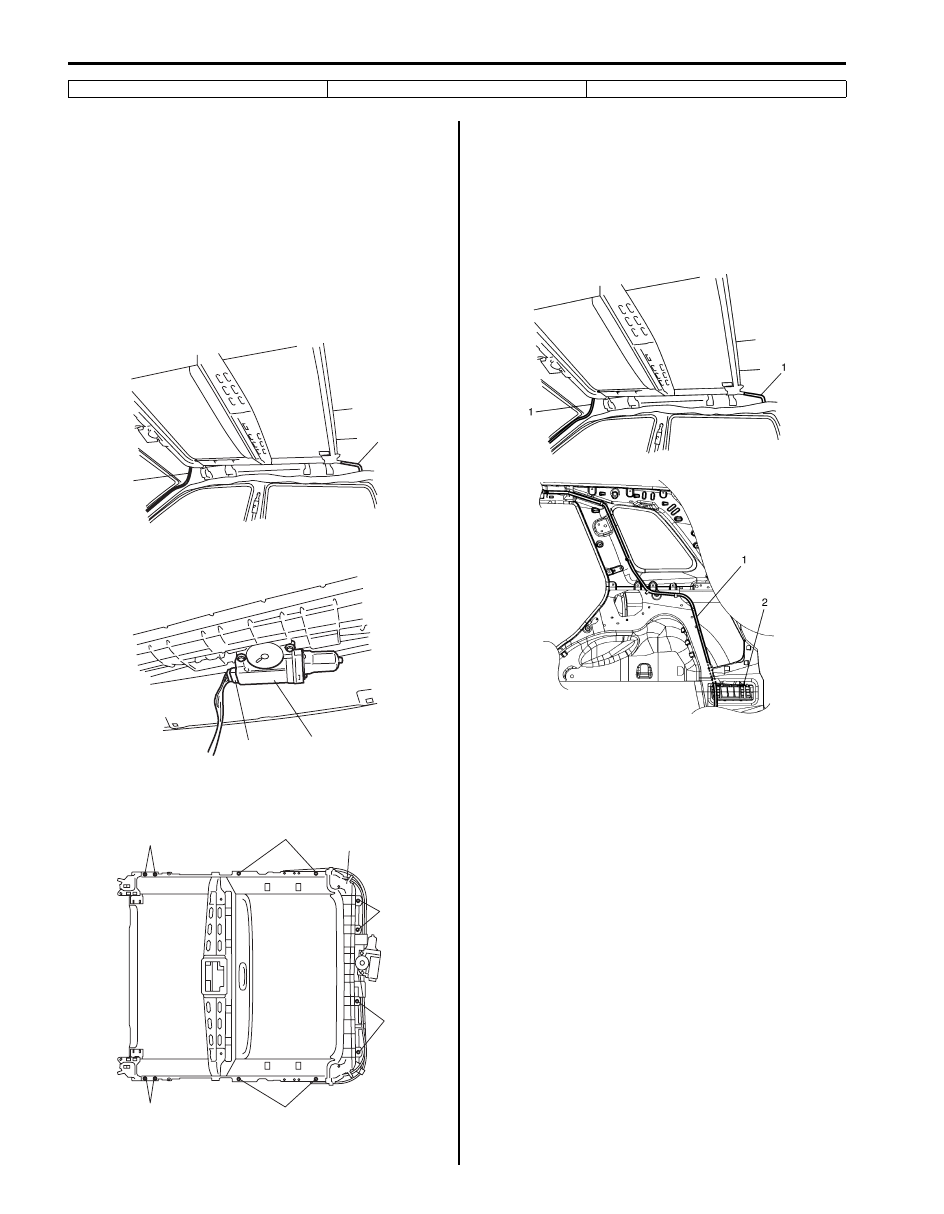
3) Disconnect drain hoses (1) connected to sliding roof 

assembly at 4 locations.

4) Disconnect sliding roof motor (1) at coupler (2).

5) Remove 8 nuts (1) and 4 bolts (2), then remove 

sliding roof assembly (3).

Installation
For installation, reverse removal procedure, noting the 
following points.
• Connect drain hoses (1) to sliding roof assembly at 4 

locations. Clamp drain hose by each clamp securely.

• Pass rear drain hose between rib of outlet ventilator 

(2).

• Initialize sliding roof position data referring to “How to 

reactivate the system to prevent being pinched by the 
sunroof” in Sunroof section of Owner’s manual.

• After reinstalling sliding roof assembly, be sure to 

make glass adjustment. (Refer to “Sliding (Sun) Roof 
Glass Adjustment”.
)

5. Deflector

10. Drive cable

1

1

I5JB0A990010-01

1

2

I5JB0A990011-01

1

1

1

1

2

2

3

I5JB0A990012-01

I5JB0A990013-01

Sun Roof / T-Top / Convertible Top:  9I-6

Sliding (Sun) Roof Assembly Disassembly and 
Reassembly

S6JB0A9906009

Disassembly

1) Remove sliding roof motor (1).

2) Slide sunshade (1) to full-position.
3) Remove deflector (2) from holder (3) with holding 

deflector.

4) Remove No.1 peaces (1) and then pull out sunshade 

(2) from guide rails (3).

5) Remove rail stoppers (4) from guide rails.

6) Pull out drip channel (1), panel brackets (2), shoes 

(3) and drive cables (4) all together from guide rails.

7) Disassemble drip channel, panel brackets, shoes 

and drive cables.

8) Remove guide block (1) and housing covers (2) from 

rails.

Reassembly
Reverse disassembly procedure for reassembly, noting 
the following.
• Check wear and damage of drive cables and sliding 

roof motor gear.

• Apply grease to sliding part.
• Slide shoes (1) to contact guide blocks (2) for 

positioning the sliding roof to tilt up position and install 
sliding roof motor.

1

I5JB0A990014-01

1

2

3

I5JB0A990015-01

1

2

3

4

I5JB0A990016-01

1

2

3

4

I5JB0A990017-01

1

2

I5JB0A990018-01

1

2

I5JB0A990019-01

9J-1 Hood / Fenders / Doors: 

Body, Cab and Accessories

Hood / Fenders / Doors

Repair Instructions

Hood Removal and Installation

S6JB0A9A06001

Removal

CAUTION

!


Place cloth to prevent body from any 
damage.


1) Remove hood silencer (4).
2) Disconnect window washer hose (1) from hood.
3) Remove 4 mounting bolts (3) to detach hood (2).

Installation
Reverse removal procedure noting the following.
• Apply sealant to contact face “A” of hood hinge.

“A”:  Sealant 99000–31110 (SUZUKI Bond 
No.1215)

• Adjust hood lock position if necessary referring to 

“Hood Inspection and Adjustment”.

Hood Inspection and Adjustment

S6JB0A9A06002

Inspection
• Check that hood opens and closes smoothly and 

properly. Lubricate if necessary.

• Check that hood stops in the secondary latched 

position properly (preventing hood from opening 
freely) and that hood closes completely in the fully 
latched position.

• Adjust hood lock position, if necessary.

Adjustment
Adjust the following point:
• Hood position adjustment.
• Fore-and-aft and right-and-left adjustment.

Adjust hood clearance by loosening hood mounting 
bolts. Refer to “Panel Clearance in Section 9K”.

• Vertical adjustment

If only one side (right or left) of hood is not level with 
front fender, make it level by tightening or loosening 
hood cushion (1).

• Hood lock position adjustment

a. Loosen hood lock bolts.
b. Adjust hood lock height position so the hood is 

locked without looseness.

c. Tighten hood latch bolts to specified torque.

Tightening torque
Hood latch bolt (a):  10 N·m (1.0 kgf-m, 7.5 lb-
ft)

d. Make sure the hood is locked smoothly and 

securely.

4

2

1

3

“A”

“A”

I5JB0A9A0001-01

I5JB0A9A0002-01

(a)

(a)

I5JB0A9A0003-01

Hood / Fenders / Doors:  9J-2

Front Fender Components

S6JB0A9A06003

Front Fender Removal and Installation

S6JB0A9A06004

Removal

1) Remove splash guard (if equipped) referring to “Splash Guard Removal and Installation (If Equipped) in Section 

9M”.

2) Remove front fender lining.
3) Remove front bumper referring to “Front Bumper Components in Section 9K”.
4) Remove headlight assembly referring to “Headlight Housing Removal and Installation in Section 9B”.
5) Remove cowl top garnishes referring to “Cowl Top Components in Section 9K”
6) Disconnect connector from side turn signal lamp.
7) Remove front fender.

Installation
Reverse removal procedure to install front fender noting the following instruction. 
• If paint on fender bolt is peeled off, be sure to apply paint again.
• Adjust panel clearance referring to “Panel Clearance in Section 9K”.

1

3

2

4

I5JB0A9A0004-02

1. Front fender lining

3. Front fender rear pad

2. Front fender

4. Splash guard (if equipped)


Content   ..  508  509  510  511   ..